DMC SCU80P User manual

1
Operation Manual
Air Compressor for Diving
Gas Engine Driven Series
SCU80P

2
INDEX
1. GENERAL
2. TECHNICAL DATA
3. STRUCTURAL PRINCIPLE
3.1 COMPONENTS
3.2 COMPRESS PROCESS
3.3 PUMP UNIT
3.4 GAUGE, SAFETY VALVE
3.5 PRESSURE SWITCH
3.6 ELECTRIC STARTER
3.7 DRAIN VALVE
4.OPERATE
4.1 INSTALLATION
4.2 BEFORE OPERATION
4.3 RUNNING
5. MAINTAINENCE
5.1 LUBRICATE
5.2 AIR FILTER
5.3 PURIFY FILTER
6. TROUBLESHOOTING
7. CIRCUIT DIAGRAM

3
1
SAFETY CAUTIONS
Please read this operation manual carefully before installation and operation
This series are high pressure air compressor. It compresses atmosphere air go to
pressure 0.3/0.8Mpa, 45/110psi, after be purified and separated by the filter and
separator.
It discharge clean air accords to GB18435-2001 breathing air standard. It is widely be
used for breathing of diving and fire fighting; paintball PCP shooting and other high
pressure filed industries by its reliability, durability and portability.
Products range include:
-- DC 12V
-- AC 110V 220V
-- Gas engine driven
Optional accessories : diving hose and musk

4
■Check the electric voltage in nameplate is same as your local electric supply
■Check the lubricate oil has been put in before running
■Increase rated pressure setting is forbidden
■There is potential danger of pipe burst or connect fitting blow off under high pressure, please avoid
body too near compressor when it running
■if there are no auto stop function, don't leave compressor until it reach rated pressure and shut
down it by manual

5
2
TECHNICAL DATA
SCU80P / Gasoline Engine Driven Diving air compressor
Charging Rate: 250L/min; 8cfm
Suction pressure: atmosphere
Working pressure: 0.8MPa,8bar, 110psi
Media: air
No.of stage and cylinder: 1
Engine power: 5HP / HONDA
Cooling: air
Driven: belt driven
Shout down:Automatic stop by pressure switch
Pressure indicate:Gauge
Protection :Safety valve in outlet
Filtration:water separator and breathing filter
Lubricant: ISO grade 100# compressor oil
Dimension:850 X 400 X 500mm
Weight:50kg
Noise:Less than 70 dB(A)
Receiver tank: 10 liters stainless steel tank
Outlet: 2 ports, with outlet pressure regulator

6
3
STRUCTURE
3.1 Main Components
3.2 Working process
Atmosphere air is sucked into cylinder of the compressor, and compressed to reach
0.3Mpa/0.8MPa 40/110 psi pressure, through regulator with water separator , then
purified by filter. Discharge clean air for diving breathing.
3.3 Pump unit
The pump block unit is composed of crankcase, crankshaft, cylinder, piston, intake and
discharge valves, connect rod , bearing etc.
It is oil less belt driven type compressor.

7
3.4 Gauge & safety valve
The pressure gauge is installed in final stage of the compressor to display discharge
pressure.
The safety valve is installed at the place of discharge to take the overpressure
protection. If the discharge pressure is higher than preset value, the safety valve will
open and release pressure.
Note: do not adjust the safety valve, otherwise it will result in serious damage
3.5 Pressure switch
The compressors are preset rated working pressure as per order require. The
compressor will stop automatically when pressure reach rated pressure. And re-start
compressor when pressure is lower than minimum.
Note: don’t try to adjust it if not get authorized
3.6 electric starter
Start gasoline / petrol engine
3.7 drain valve
Open valve under receiver tank to drain moisture water in tank.

8
4
INSTALL AND OPERATION
4.1 Installation
The compressor must be mounted on a firm, level base Where is with well-ventilated
and rain-proof , non-hazardous locations
The environment temperature is required to be lower than 40 degree C.
4.2 Check before running
Oil level check
Check the oil level which must be keep between max. and min. line.
Note: if the oil level is too high, air valves will carbonize, if it is too low , will
result in insufficient lubrication and cylinder sticking
-- Check connect fitting and valve to make sure no leakage
-- Check rotary direction of motor, the right direction should be a cooling wind to the
cylinder
--install intake air filter on pump block
4.3 Running
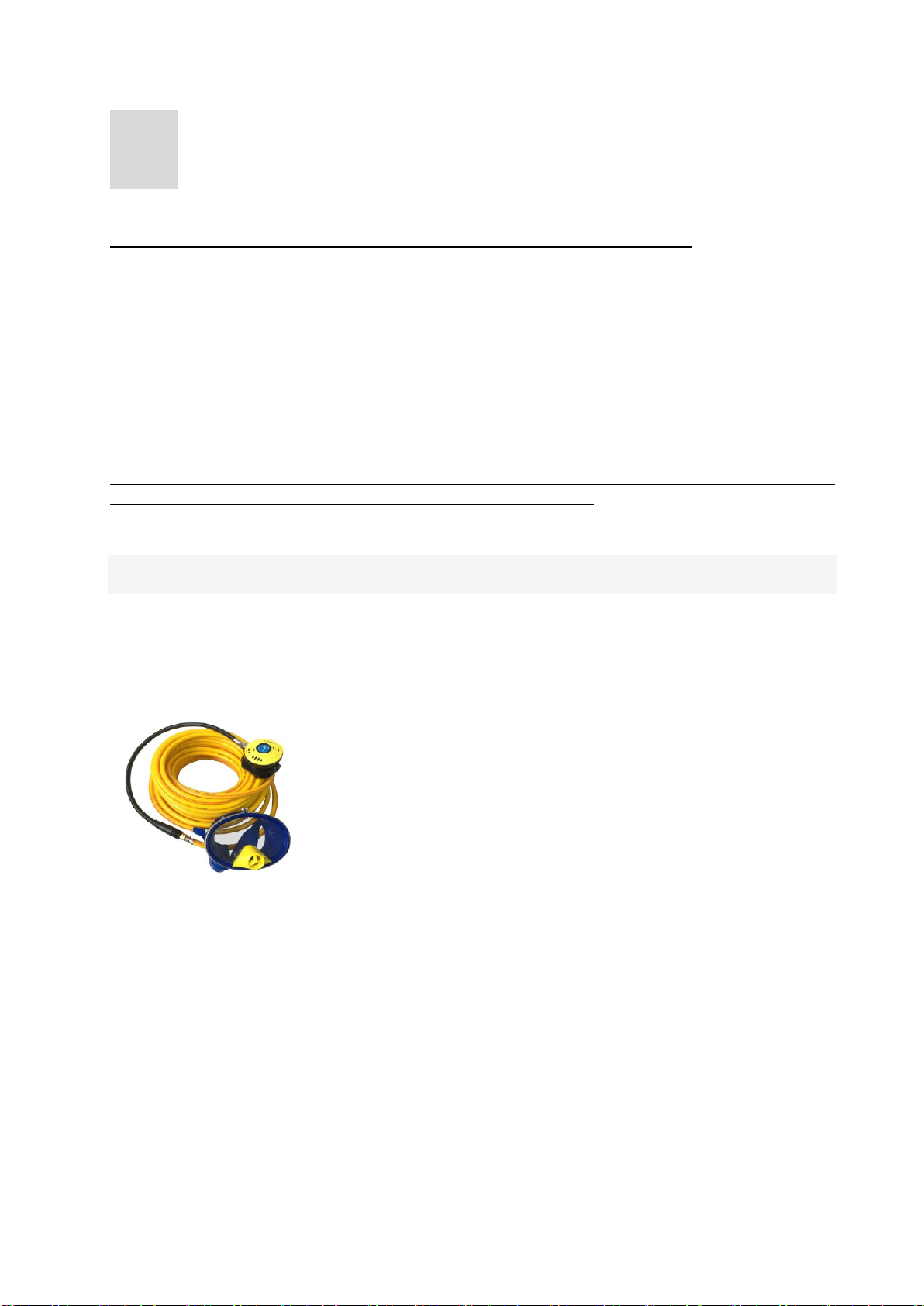
1. Connect air hose to discharge outlet port with fast plug in coupling
2. Open discharge check valve
3. Close drain valve under air tank
4. Start engine to run compressor
5. Compressor will download automatically when reach rated pressure
( presetting unload pressure is 0.8Mpa/ 8bar/ 110psi),
and load again when pressure drop down to minimum pressure
( presetting load pressure is 0.5Mpa/ 5bar/ 75psi)
6. Turn around regulator to make discharge pressure go through air hose to suitable for
mask breathe.
7. Shut off engine to stop compressor when finish work

9
5
MAINTENANCE
General maintenance interval
Every
refill
5 h
25 h
30 h
50 h
100 h
1000
h
annually
Oil level check
△
◆
◆
Belt tension
△
◆
Air intake filter
△
◆
◆
Safety valve
check
△
Hose and fitting
check
△
◆
△ Check ◆ replace
5.1 lubricate oil
Oil level must be checked every 25 hours; oil must be replaced after 100 working hours
or annually, and 50 working hours to change oil for the first time. DMC SYNTHETIC oil,
MOBIL SPECIAL 20W50, MOBIL RARUS 827-829, ANDEROL 755 SYNTHETIC are
recommended.
Warning: it is forbidden to mix different brand or ISO grade oil for lubricate
△ Check ◆ replace
5.2 air filter
blow air filter by compressed air to clean dust.
The air filter element must be changed every 2000 working hours or annually.
5.3 Filtration for breathing air (ACTIVE CARBON FILTER)
The outlet air purification depends on the activated carbon and molecular sieve, so filter
elements must be replaced periodically, especially for breathe purpose. Follow are
advice interval time.
Ambient
temperature(℃
)
Capacity(L)× Number
Time for change(hour)
40
6×55
10
30
6×100
18
20
6×160
30
10
6×300
55

10
5
6×400
75
0
6×600
110
Note: Filter elements must be replaced at once if people feel particular smell.
Replacement: open the filter cover; replace the active carbon in bottle

11
6
TROUBLESHOOTING
Fault Reason
Over
low P
Over
high P
Over
noise
Over
heat
Not
start
Air
leak
Pressure switch damage
√
√
Motor capacitor damage
√
safety valve damage
√
√
√
drain valve damage
√
√
Discharge valve damage
√
√
√
Piston ring damage
√
√
protector shut off
√
foot damage
√
Solenoid valve damage
√
√
One way valve damage
√
√
DC/AC power too low
√
√
intake filter block
√
In/out valve damage
√
√

12
7
CIRCUIT DIAGRAM
Table of contents
Popular Air Compressor manuals by other brands

Kroll
Kroll UBK 2 manual

COLTRI
COLTRI HEAVY DUTY Series Use and maintenance manual

Focusrite
Focusrite Sonible Fast manual

Woodstar
Woodstar cp 16 Translation from original manual

Campbell Hausfeld
Campbell Hausfeld Extreme Contractor Series operating instructions

Craftsman
Craftsman 921.166400 owner's manual

CO/Tech
CO/Tech VZB-0.14/8-VFL-50 Original instructions

SereneLife
SereneLife SLPUMP30 user manual

Central Pneumatic
Central Pneumatic 95370 Assembly and operation instructions

C-Aire
C-Aire S260R-LD1-115P owner's manual

Emax
Emax HULK POWER HP15P004SS operating instructions

Central Pneumatic
Central Pneumatic 47915 Assembly and operating instructions