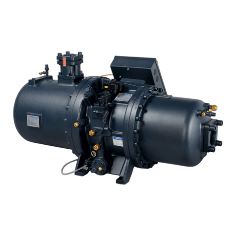
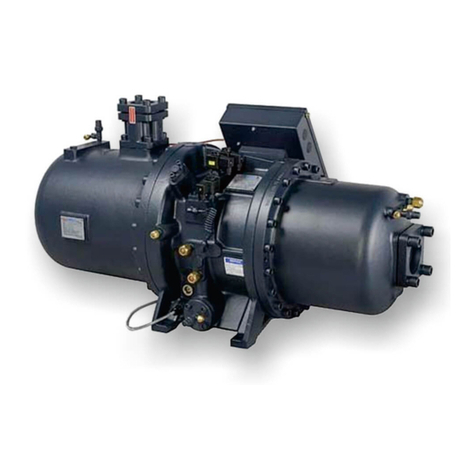
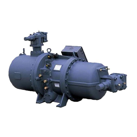
Hanbell RC2-AVI Series User manual

1. General........................................................................................................................................ 1
2. Specifications and designs ....................................................................................................... 1
2.1 Compressor nomenclature............................................................................................... 1
2.2 Compressor specifications .............................................................................................. 2
2.3 Compressor construction................................................................................................. 2
2.4 Design features.................................................................................................................. 4
2.5 Compression process....................................................................................................... 4
2.6 VFD application ................................................................................................................. 5
2.7 Capacity control system................................................................................................... 5
2.8 Volume ratio (Vi)................................................................................................................ 6
2.9 Application limits............................................................................................................... 7
3. Lubricants ................................................................................................................................... 8
3.1 Lubricants table................................................................................................................. 9
3.2 Suggestions of changing oil............................................................................................. 9
3.3 Oil change.......................................................................................................................... 9
4. Compressor lifting and installation......................................................................................... 10
4.1 Compressor lifting........................................................................................................... 10
4.2 Compressor mounting.................................................................................................... 10
4.3 Compressor outline......................................................................................................... 12
4.4 Accessories ..................................................................................................................... 18
5. Electrical data and design ....................................................................................................... 30
5.1 Motor design.................................................................................................................... 30
5.2 Electrical installation with VFD ...................................................................................... 30
5.3 V-F diagram...................................................................................................................... 30
5.4 Protection devices........................................................................................................... 31
5.5 Grounding........................................................................................................................ 31
6. Operation and maintenance .................................................................................................... 32
6.1 Start-up............................................................................................................................. 32
6.2 Troubleshooting.............................................................................................................. 33
7. Applications.............................................................................................................................. 35
7.1 Additional cooling........................................................................................................... 35
7.2 Parallel system applications .......................................................................................... 38
7.3 Oil pump application....................................................................................................... 38
7.4 Inverter cooling................................................................................................................ 39
7.5 Important notes of applications..................................................................................... 39
8. Selection program.................................................................................................................... 40
9. Warranty.................................................................................................................................... 41

1
1. General
HANBELL RC2-AVI series semi-hermetic screw compressor is developed for variable frequency drive (VFD)
applications in air-conditioning and refrigeration. It inherits our experience in RC2 design and enhances the mechanism
of capacity modulation and motor insulation for VFD applications. Each HANBELL compressor is precisely
manufactured by THREAD SCREW ROTOR GRINDING MACHINE, CNC MACHINING CENTER, and inspected by 3D
COORDINATE MEASURING MACHINE. The advanced 5-to-6 Patented Screw Rotor Profile ensures high efficiency in
different range of operating conditions.
Quality management system in HANBELL complies with the ISO 9001 requirements. The ISO 9001 certification assures
customers that HANBELL products are manufactured within a uniform and consistent quality system from the time an
order is placed until shipment.
RC2-AVI series compressor is equipped with liquid injection connector, economizer port, PTC motor temperature
thermistors, discharge temperature thermistors, motor protector, oil level switch and oil pressure differential switch
connector for additional cooling and compressor protection. These accessories guarantee the compressor with the
highest reliability and longest bearing life under heavy or strict operating conditions.
This Technical Manual contains information of compressor specifications, installation, environment setting, applications
and basic trouble-shooting. To prevent any possible incorrect operations, it is highly recommended to read these
instructions prior to installing and commissioning the compressor. Please contact HANBELL or its local distributors for
farther information and assistance.
2. Specifications and designs
2.1 Compressor nomenclature
RC 2 – x x x x A V I
RC model 2
nd
Version
Compressor’s Displacement at
50Hz (m
3
/hr)
Refrigerant Code
A
= R134a
VFD
Application
Variable V
i

2
2.2 Compressor specifications
a. RC2-AVI
Note:
It is recommended to install a second oil separator if SCT is above 50 (122 ) .
Nominal Horse Power:
All the above Nominal Hp’s are not equal to the maximum compressor Hp. Please refer to Hanbell selection software’s
output for rated current according to various operating conditions while selecting contactor, cable, fuse and wire, etc…
2.3 Compressor construction
Figure 2.1.1:RC2-140AVI Construction
Item
Description Item
Description Item
Description Item
Description
1 Compressor casing 9 Oil separator cartridge 17 Discharge fixed ring 25 Refrigeration Lubricant
2 Motor casing 10 Piston 18 Disc spring 26 Suction flange
3 Oil separator 11 Piston spring 19 Bearing lock nut 27 Discharge flange
4 Motor rotor assembly 12 Piston rod 20 Male rotor 28 Cable box
5 Motor stator assembly 13 Bearing seat’s cover plate
21 Suction bearings 29 Power bolt
6 Motor rotor washer 14 Modulation slide valve 22 Oil filler cartridge 30 Motor cable cover plate
7 Motor rotor spacer ring 15 Slide valve key 23 Suction filter 31 Discharge check valve
8 Oil separator baffle 16 Discharge bearings 24 Oil heater
Model
Compressor Motor
Lubricant
Charge
Oil
Heater
Hydrostatic
Pressure Test
Weight
Displacement
70Hz / 80Hz
(m
3
/hr)
Rated Speed
(rpm) Vi
Type
Nominal
Hp
Starting
Voltage
80Hz(V)
Insulation
Protection
L W
kg/cm
2
g
kg
RC2-140AVI 189/219
1,200~4,800
(20~80Hz)
1.6
-
2.0
-
2.4
or
2.4
-
3.0
-
3.5
3 Phase, 2 Pole, Variable Speed, Induction Motor
42
Inverter
staring
220/
380~460
Class F
PTC
7
150/
300
42
295
RC2-260AVI 356/411 78
14
575
RC2-300AVI 410/469 90 16
620
RC2-340AVI 475/542 102 16
630
RC2-410AVI 567/651 125 16
760
RC2-470AVI 660/754 144 18
830
RC2-550AVI 769/878 168 23
850
RC2-620AVI 867/990 182 23
880
RC2-830AVI 1159/1324
1150~4150
(20-70Hz)
243 28 1180
RC2-1020AVI 1428 (70Hz) 265
(70Hz)
40 1530
RC2-1270AVI 1775 (70Hz) 333
(70Hz)
53 2130

3
Figure 2.1.2:RC2-260AVI, RC2-300AVI, RC2-340AVI, RC2-410AVI,
RC2-470AVI, RC2-550AVI, RC2-620AVI, RC2-830AVI Construction
Item Description Item
Description Item
Description Item
Description
1 Compressor casing 10
Piston 19
Disc spring 28
Suction flange
2 Motor casing 11
Piston spring 20
Bearing lock nut 29
Discharge flange
3 Oil separator 12
Piston rod 21
Male rotor 30
Cable box
4 Motor rotor assembly 13
Bearing seat’s cover plate
22
Suction bearings 31
Power bolt
5 Motor stator assembly 14
Modulation solenoid valve
23
Suction bearings inner/outer
spacer ring 32
Thermostat terminals
6 Motor rotor washer 15
Modulation slide valve 24
Oil guiding ring 33
Motor cable cover plate
7 Motor rotor spacer ring 16
Slide valve key 25
Suction filter 34
Discharge check valve
8 Oil separator baffle 17
Discharge bearings 26
Oil heater
9 Oil separator cartridge 18
Discharge fixed ring 27
Refrigeration Lubricant
Figure 2.1.3:RC2-1020AVI, RC2-1270AVI
Item
Description Item
Description Item
Description Item
Description
1 Compressor casing 11
Piston spring 21
Bearing slot nut 31
Suction flange
2 Motor casing 12
Piston rod 22
Male rotor 32
Discharge flange
3 Oil separator 13
Bearing seat cover plate 23
Suction bearings 33
Cable box
4 Motor rotor assembly 14
Modulation solenoid valve 24
Suction bearings
inner/outer
spacer ring 34
Power bolt
5 Motor stator assembly 15
Modulation slide valve 25
Oil guiding ring 35
Thermostat terminals
6 Motor rotor washer 16
Slide valve key 26
Oil level sight glass 36
Motor cable cover plate
7 Motor rotor spacer ring 17
Discharge bearings 27
Oil filler cartridge 37
Discharge check valve
8 Oil separator Baffle 18
Discharge fixed ring 28
Suction filter
9 Oil separator cartridge 19
Disc spring 29
Oil heater
10 Piston 20
Balance piston 30
Refrigeration Lubricant

4
2.4 Design features
HANBELL screw compressors feature simple and robust construction by elimination of some components such as
pistons, piston rings, valve plates, oil pumps which are usually found in reciprocating compressors. Without these
components, screw compressors are running with minimum noise and vibration level and high reliability and durability.
HANBELL screw compressors are of two-shaft rotary displacement design with the advanced 5:6 patented screw
rotors. Screw rotors are precisely installed with roller bearings, i.e. radial bearings at both suction and discharge ends
as well as angular contact ball bearings i.e. axial bearings at discharge end. A three-phase, two-pole, squirrel-cage
dedicated induction motor drives the compressor. The motor rotor is affixed with the shaft of the male screw rotor.
Cooling of the motor is achieved with suction refrigerant vapor.
Compressor technical features:
Automatic variable volume ratio- Compressor’s Vi is adjustable, which reduce the risk of efficiency loss when the
working condition may vary at job site. Peak and off-peak operation conditions can be taken into account at the same
time. Automatic variable volume ratio ensures no loss of work in various working condition.
Variable frequency drive (VFD)
-
Variable frequency drive efficiently adjusts motor speed to match output
requirements and save energy.
Full product range- RC2-AVI series compressor consists of 11 models with displacement ranging from 140 m
3
/hr to
1775 m
3
/hr.
Multinational patents of high-efficiency screw rotors- The new 5:6 high efficiency screw rotor profile is patented in
Taiwan, UK, US, and China. This large-volume, high-efficiency rotor profile is designed especially for modern
refrigerant characteristics. High-efficiency screw rotors are accomplished by using precise CNC machining centers,
rotor milling machines, rotor grinding machines. Quality system certified by ISO 9001 with precise measuring
equipment such as ZEISS 3D coordinate measuring machines, ensure high-efficiency, high-quality, low-noise and low-
vibration HANBELL RC2-AVI series screw compressors.
High efficiency motor- Premium grade low-loss core steel with special motor cooling slot and refrigerant guide vane
pilots the cold suction refrigerant gas going through the motor, providing high efficiency under different operating
conditions. Its winding and insulation is specially made for variable speed drive applications.
Long life bearings and high reliability- The screw compressors utilize a combination of 10 axial and radial bearings
with αaxial balance piston to ensure longer bearing life and higher compressor reliability.
Double-walled rotor housing- Double-walled casing structure with high strength inner ribs is designed to minimize
noise and vibration level. The rotor housing is made of high-strength gray cast iron FC25 that is extremely stable.
These casings are machined by computer aided machining centers and inspected by precision measuring machines.
Direct flange-on oil separator- A vessel made of ductile material FC500 specially designed to withstand high
pressure and provide the highest efficiency of oil separation. Simple oil management, three-staged oil separator, low-
pressure-drop demister ensures the minimum refrigerant dilution in the oil and maintain high oil viscosity.
Perceptive protection modules- RC2-AVI series screw compressors are equipped with PTC thermistors and motor
protection module which can monitor discharge and motor coil temperatures. Accessories also include oil level switch
to monitor the level of oil, pressure differential switch connector, and optional pressure relief valve.
Adaptable with additional cooling- Liquid injection connectors on motor casing and the compression casing maintain
proper temperature of lubricant and prevent the compressor from overheat. Similarly, oil cooler connectors for the
external oil cooler application can reduce discharge temperature and gives better efficiency. The middle pressure
economizer connection port can be used to achieve higher refrigeration capacity and system efficiency through a sub-
cooling circuit and two-stage refrigeration expansion.
2.5 Compression process
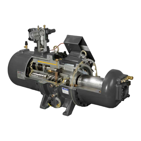
(A) Suction and sealing:
At the beginning of the compression cycle, as the male rotor and female rotor unmesh, gas from suction port fills
the interlobe space (refer to the dark area below). Refrigerant at suction pressure continues to fill it, until the trailing
lobe crosses the suction area and the gas is trapped inside the interlobe space.
(B) Compression:
As the male rotor and female rotor mesh with each other, the interlobe space moves towards to discharge end and
its volume shrinks so that gas pressure increases consequently.
5
(C) Discharge:
Gas is discharged from the interlobe space when the leading lobe crosses the discharge port with designed volume
ratio.
Figure 2.2: Compression process
2.6 VFD application
The following are the instructions that explain the variable frequency drive (VFD) applied in RC2-AVI series screw
compressor. Please read all of the instructions before commissioning.
1. Maximum rotation frequency must be within nominal rotation frequency of the motor; minimum rotation frequency is
variable under specified working condition (please refer 2.9 Application Limits).
2. If the compressor has to operate outside the frequency spectrum mentioned above, please consult Hanbell before
commissioning. Higher or lower rotation frequency may result in lower efficiency or damage to the compressor and
motor.
3. Wiring of chiller controller and compressor protection modules such as PTC thermistors or oil level switch should
be insulated from wiring of the VFD’s power input/output for prevention of interference.
4. The VFD and the compressor must be well-grounded respectively.
5. Nullify functions of phase loss and phase sequence in motor protector INT69HBY for their duplication in the VFD’s
protection and prevention of interference.
6. To prevent reverse running of compressors due to incorrect wiring, verification of high/low pressures should be
monitored by pressure switches or programming in commissioning.
7. Compressor high/low pressure difference should be kept above 4kg/cm
2
, especially under very low rotation speed.
If an external oil circuit is used, the oil flow switch should be installed and oil pressure in the main oil return line
should be monitored for adequate lubrication of compressors.
8. If high/low pressure difference or oil pressure in the main oil return line can’t be maintained, an oil pump or
pressure regulation valve must be installed.
2.7 Capacity control system
The mechanism of capacity modulation of RC2-AVI is achieved by the variation of motor’s rotation speed.
Compared to modulation by slide valve, adjustable rotation speed through VFD significantly enhances efficiency of
compression, especially volumetric efficiency at part load. On the other hand, VFD can supply motor adequate voltage
and power input based on the requirement; in this way, variation of power input during capacity modulation becomes
more linear and that reduces unnecessary power losses. Overall, capacity modulation by VFD is superior to that by
slide valve in volumetric efficiency and power consumption.
Capacity modulation by VFD is similar to stepless capacity modulation by slide valve. As long as VFD receives analog
signals e.g. DC 0~10V or 4~20mA from PLC or microcontroller, it can make compressors run at corresponding rotation
speed proportionally to achieve capacity modulation.
To let PLC or microcontroller control VFD stably, pay attention to the following notes:
1. Wiring for analog signals should be well-insulated to prevent interference and noise.
2. Wiring for signals connected to VFD should be isolated from VFD power supply at a distance.
3. PLC or microcontroller as well as VFD should be well-grounded respectively to prevent cross interference.
Procedures for initial setting are as follows:
1. When completing VFD setting, remove wiring of VFD power output, and check if VFD’s output frequency and
corresponding voltage comply with PLC or microcontroller’s output signal, e.g. for DC 0~10V with 380V/3P/80Hz
motor, when analog signal is 10V, VFD’s output should be 80Hz and 380V; when analog signal is 7.14V, VFD’s
output should be 57Hz and 272V and so on.
2. VFD’s output current can’t be verified under no load but its frequency and output voltage still can be registered by
VFD’s display. Because VFD’s output voltage is not normal A/C voltage, it can’t be measured by general clamp
meter.
3. In addition to analog signals, other communication between microcontroller and VFD should be checked as well,
such as VFD’s failure feedback or reset command…etc.
(A) Suction and sealing
(
B) Compression
(C) Discharge

6
V
Pd
Pd'
V
Pd<Pd'
P
Pd, Pd'
V
Pd=Pd'
P
Pd>Pd'
Pd'
Pd
P
2.8 Volume ratio (Vi)
The volume ratio (Vi) of the compressor can be defined as the ratio of suction volume to discharge volume in the
compressor. The smaller the concavity of slide valve in the discharge end, the larger the volume ratio. The volume ratio
directly affects the internal compression ratio (Pi). Low Vi corresponds to low Pi and high Vi corresponds to high Pi. In
the equation below, in order to prevent over or under compression, the system compression ratio (CR) should be equal
to compressor’s internal compression ratio (Pi). Please refer to P-V (pressure – volume) diagram below to figure out
this relation. Following the concept above, if the Vi varies with working condition, there will be less loss of work. High
efficiency can be achieved. In RC2-AVI series, Vi 1.6-2.0-2.4 or Vi 2.4-3.0-3.5 is provided to correspond to various
working condition.
CR = Pd/Ps
Pi = Vi
k
Vi = Vs/Vd
Where: CR: system compression ratio Pi: internal compression ratio
Vi: internal volume ratio Pd: system pressure (absolute pressure)
Pd’: discharge pressure (absolute pressure) Ps: suction pressure (absolute pressure)
Vs: suction volume Vd: discharge volume K: refrigerant specific heat ratio
In RC2-AVI, compression volume is adjustable through two solenoid valves. The mechanism improves the power
efficiency under different working conditions, especially when the compressor runs at part load. The control logic is
based on the equations belows
Vi = Vs/Vd; Vs: suction volume, Vd: discharge volume
(Vi)
k
= Pd/Ps; Ps: suction pressure (absolute pressure), Pd: system pressure (absolute pressure) k: coefficient
Figure 2:4: Mechanism of variable Vi
In water cooled and air cooled system, the volume ratio can be set at 1.6, 2.0, 2.4 and 2.4, 3.0, 3.5, respectively.
Following tables show the control logic of solenoid valve under different Vi:
Under compression (CR > Pi)
Over compression (CR < Pi)
CR = Pi
Loss of work Loss of work
1 2
3
4
Ps
1 2
3
4
Ps
Ps
1
2
3
4
Figure 2.3: P-V Diagram

7
Vi SV2 SV1
1.6 Off Off
2.0 On Off
2.4 Off On
Figure 2.5: Vi control (Water-cooled system)
Vi SV2 SV1
2.4 Off Off
3.0 On Off
3.5 Off On
Figure 2.6: Vi control (Air-cooled system)
2.9 Application limits
The application limits shown below are based on saturated suction and discharge operating conditions, for continuous
operation over extended periods of time. It is important to operate within these limits to maintain proper compressor life.
Operating at extra low saturated suction temperature, may cause oil management and motor cooling problems, while
operating at extra high saturated condensing temperature will shorten the compressor life due to insufficient motor and
compressor chamber cooling.

8
Notes:
1. When Hanbell screw compressors operate in partial or full load at application limits, motor coil and discharge
temperature will rise simultaneously. In order to keep compressors’ safe running continuously, Hanbell
recommends usage of the following additional cooling devices :
(1)Oil cooler or (2)Liquid injection to chamber or (3)Liquid injection to motor.
Please refer to Hanbell selection software for application of additional cooling system.
2. Hanbell recommends monitoring oil pressure and keeping it 4 kg/cm
2
g over the suction pressure for adequate seal,
lubrication by pressure differential switch passively or by additional oil pump actively. Especially under operation
conditions with low condensing temperature and high evaporating temperature like application in flooded water-
cooled chillers, high-low pressure differential tends to be less than 4kg/cm
2
g, installation of oil pump is
recommended to ensure adequate oil pressure.
Contact Hanbell to verify potential operating conditions outside the application limits as shown.
3. The minimum discharge superheat is recommended to be kept 10K higher than the condensing temperature
(normally discharge superheat is around 20K for R134a) to avoid liquid’s filling back to compressor and lubrication
failure.
3. Lubricants
The main functions of lubrication oil in screw compressors are lubrication, internal sealing, and cooling. The design of
positive pressure differential lubrication system makes RC2-AVI series normally omit an extra oil pump which is
necessary for reciprocating compressors. However, in some special applications, it is still necessary to install an extra
oil pump to screw compressors for safety.
Bearings installed in RC2-AVI series compressors require a small and steady quantity of oil for lubrication. Oil injection
into the compression chamber creates a film of oil for sealing in the compression housing to increase efficiency and
also can dissipate part of compression heat.
Please pay more attention to the oil temperature, which is crucial to compressor bearings’ life. Oil has a much lower
viscosity at high temperatures. Too low viscosity of oil will result in poor lubrication and heat dissipation in the
compressor. Viscosity is recommended to keep over 10mm
2
/s at any temperatures for oil. Oil temperature in the oil
sump should be kept above the saturated condensing temperature to prevent refrigerant migration into lubrication
system.
If the compressor operates under critical operating conditions, an extra oil cooler is required – please refer to Hanbell
selection software for the required capacity and oil flow of the extra oil cooler. High-viscosity oil is recommended to
apply in high operating conditions because high discharge temperatures will make viscosity of oil lower. Oil return from
the evaporator may be insufficient in such as refrigeration systems, flooded chillers…etc. , in which it’s difficult for oil to
be carried back and it may cause oil loss in the compressor. If the system encounters the oil return problem, then an
extra 2
nd
oil separator is recommended to be installed between the compressor discharge port and the condenser.
RC2
-
140AVI~
62
0AVI
RC2-830AVI~1270AVI

9
3.1 Lubricants table
Hanbell Authorized Lubricant for R134a
SPECIFICATION UNITS HBR-B05 HBR-B08 HBR-B09 HBR-B04
COLOR, ASTM
−
−
−
−
SPECIFIC GRVITY 0.945 0.94 0.95 0.95
VISCOSITY 40
mm
2
/s (cSt)
64 131 175 215.9
100
8.9 14.53 16.5 20.8
FLASH POINT 266 254 265 271
POUR POINT -43 -36.5 -30 -25
T.A.N mg KOH/g
−
−
−
−
COPPER STRIP
100 /3hr−−−−
MOISTURE ppm
−
−
−
−
FLOC POINT
−
−
−
−
DIELETRIC STRENGTH
2.5mm kV −−46.6 −
Note: For using non-HBR lubricants, please consult HANBELL for more information.
3.2 Suggestions of changing oil
1. Use Hanbell certified oil and do not mix different brands of oil together. Choice of oil should match characteristics of
the refrigerant used. Oil remained in the compressor should be totally cleaned up before charging different brands of oil.
Charge the compressor with oil for the first start and then change it into new oil again to ensure that there’s no mix at
all.
2. When using polyester oil for chiller systems, please make sure not to expose oil to the atmosphere for prevention
of change in its property. Therefore, it is necessary to vacuum the system completely when installing the compressor.
3. In order to ensure no moisture inside the system, it is suggested to clean the system by charging it with dry Nitrogen
and then vacuum it repeatedly as long as possible.
4. It is a must to change oil especially if the motor has burned out because acid debris may still remain inside the
system. Please follow the procedures mentioned above to change oil in the system. Check acidity of oil after 72 hours
of operation and then change it again until acidity of oil becomes normal.
5. Please contact Hanbell local distributors/agents for selection of oil.
3.3 Oil change
1. Change oil periodically: Check lubrication oil every 10,000 hours of continuous running. For the first operation of the
compressor, it is recommended to change the oil and clean the external oil filter after running 2,000 hours. Check the
system whether clean or not and then change oil every 20,000 hours or after 3 years’ continuous running while the
system operates in good condition.
2. Avoid clogging in oil filter with debris or swarf which may cause bearings’ failure. An optional oil pressure differential
switch is recommended to be installed. The switch will trip when the oil pressure differential between the primary and
secondary sides reaches the critical point and then the compressor will automatically shut down to prevent the
bearings from damage due to oil loss.

10
4. Compressor lifting and installation
4.1 Compressor lifting
Each HANBELL screw compressor has been carefully tested at the factory and every precautionary measures have
been taken to make sure that compressors will keep in perfect condition when reaching customers’ work. After the
compressor arrives at your warehouse, please check if its crate is kept in good condition and check all the compressor
accessories with shipping documents to see if there is any discrepancy.
When lifting the compressor, it is recommended to use a steel chain or steel cable which can be used for loading
capacity of minimum 1500 kg as shown in the figure below. Make sure that chains, cables or other lifting equipments
are properly positioned to protect the compressor and its accessories from damaging. Keep the compressor in
horizontal position when lifting, and prevent it from crashing or falling on the ground, hitting the wall or any other
accident that may damage it or its accessories.
4.2 Compressor mounting
The installation of the compressor in the refrigeration system should be made accessible and make sure that the chiller
base or site is far enough from the heat source to prevent heat radiation. The compressor should also be installed as
close as possible to the electrical power supply for easier connection. Keep good ventilation and low humidity condition
at the site. Make sure that the frame or support is strong enough to prevent excessive vibration and noise while the
compressor is running and must reserve enough space for compressors’ future overhauling work.
The compressor must be installed horizontally and in order to prevent excessive vibration transferred by the structure
and piping of the chiller while in operation, cushion or anti-vibration pads should be installed. The installation of the
anti-vibration pads is shown in Figure 4.3. The screws should only be tightened until slight deformation of the rubber
pads is visible.
※
It is strongly recommended to position the compressor higher than the evaporator
Figure 4.1: Lift the compressor with
steel chain or steel cable
Figure 4.2: Lift the compressor with safety ropes
Figure 4.3: Installation of anti-vibration pads

11
Suggestions on piping works
The unsuitable piping works done to the compressor could cause abnormal vibration and noise that might damage the
compressor. Take notice of the following points to prevent this situation from happening:
1. Cleanliness of the system should be kept after welding the piping to avoid any swarf or debris contained inside the
system as it may cause serious damage to the compressor during operation.
2. In order to reduce the vibration on the piping tubes, it is recommended to use copper tubes for suction and discharge
piping tubes. Copper tubes are better to minimize the vibration in the piping while the compressor is in operation. In
case steel tubes are used in piping system, then welding jobs are very important to avoid any stress in the piping. This
inner stress can cause harmonic vibration and noise that can reduce the life of the compressor. If a large-caliber
copper tube is not easily accessible and a steel tube is used instead in suction piping, Hanbell also recommends use of
a copper tube in discharge piping to best minimize abnormal vibration and noise.
3. Remove the oxidized impurities, swarf or debris caused by welding in the piping tubes, if these fall into the
compressor, the oil filter might be clogged resulting in malfunctioning of lubrication system, bearings and capacity
control system.
4. The material of suction and discharge flange bushing is forged steel and it can be welded directly with piping. After
welding the flange bushings and pipes, it must be cooled down by ambient air. Do not use water to cool it down
because water quenching is prohibited.
Installing the compressor in a sloping position
Figure 4.4 shows a 15° limit of oblique angle for installation of compressor. In case the oblique angle is higher than the
limit, compressor will be shut down easily. For special applications like the installation in ships, fishing boats, etc…,
where the oblique angle might exceed the limit, external oil separators, oil tanks and related accessories are
recommended to be installed. Please contact HANBELL or local distributors for further layout recommendation.
Figure 4.4: Limits of oblique angle for the installation of the compressor

12
4.3 Compressor outline
SI: mm Imperial: (in)
UNIT

13
UNIT
SI: mm Imperial: (in)

14

15

16
SI: mm Imperial: (in)
UNIT:

17

18
4.4 Accessories
To supply “Total Solution” for customers, Hanbell designs complete standard and optional accessories according to
various application requirements for safe and steady running and best performance of compressors.
1. Compressors standard and optional accessories
●:
::
:
△
△△
△
Standard, :
::
:Optional
Model &
Accessory
RC2 –AVI Series
RC2-140AVI
RC2-260AVI
RC2-300AVI
RC2-340AVI
RC2-410AVI
RC2-470AVI
RC2-550AVI
RC2-620AVI
RC2-830AVI
RC2-1020AVI
RC2-1270AVI
Discharge check
valve ●●●●●●●●●●●
Suction &
discharge
connection
bushings
●●●●●●●●●●●
Suction &
discharge stop
valves
PTC temp. sensor
●●●●●●●●●●●
INT69HBY motor
protector ●●●●●●●●●●●
IP54 cable box
●●●●●●●●●●●
Oil heater ●●●●●●●●●●●
Oil level switch
Oil drain valve
Liquid injection
system (solenoid
valve + expansion
valve)
Liquid injection
system (solenoid
valve + stop valve)
Horizontal check
valve
External oil
separator
External oil filter
Oil flow switch
Economizer
Economizer
muffler
Oil cooler
Oil pump
Pressure
regulation valve
Oil filter pressure
differential switch
connector
Safety valve
Explosion proof
accessories
Mounting pads
Refrigeration oil
Micro controller
Sound jacket
Temperature
sensors Pt100 or
Pt1000
– for motor coil
temp. monitoring
Note: The accessory chart is for reference only. Actual specification and accessories enclosed might vary with different
quotation and agreement respectively. If any optional accessory is required and out of above mentioned standard
accessory, please contact Hanbell for detailed specification and price.

19
2. Description of accessories
a. Suction and discharge check valve
Hanbell standard check valve is gravity-driven with characteristics of large flow volume and low pressure drop. After
shut-down of the compressor, Teflon taper guider inside can simultaneously seal up the precisely machined base of
check valve by gravity force to effectively prevent return of high-pressured gas to compressor. The gravity-driven check
valve is equipped vertically. Due to limitation of space or piping requirements, alternative horizontal check valve is
accessible.
Dia. Dimension unit: mm
A B C D E F G H I
2” 102 4 65 91 53 70 90 85 6
3″
″″
″138 4 95 121 80 100 120 108 6
4″
″″
″163 4 120 146 96 125 145 123 6
5″
″″
″203 5 150 176 122 150 175 150 6
6″
″″
″238 5 190 216 146 190 215 160 6
Dia. Dimension unit: mm
A B C D E F G H I J K L M
1 1/2”
109 5 55 76 99 6 43 60 75 M16x2 105 18 105
2” 122 5 66 91 110 6 53 70 90 M16x2 120 18 120
2 1/2″
″″
″
134 5 80 111 125 6 64 90 110
M16x2 140 18 140
3″
″″
″153 5 95 121 135 6 76 100 120
M20x2.5 160 22 160
4″
″″
″171 5 106.5
146 135 6 88 125 145
M20x2.5 185 22 185
Fig
ure
4.5:
Suction
check valve outline drawing
Figure 4.6: Discharge check valve outline drawing (Vertical type)
This manual suits for next models
12
Table of contents
Other Hanbell Air Compressor manuals

Hanbell
Hanbell LT-S Series User manual

Hanbell
Hanbell RT Series User manual

Hanbell
Hanbell RC2-D User manual

Hanbell
Hanbell RC2-100A User manual

Hanbell
Hanbell SAM-285 User manual

Hanbell
Hanbell LBII-PLUS User manual

Hanbell
Hanbell RC2-F Series User manual

Hanbell
Hanbell RC2 Series Installation manual

Hanbell
Hanbell RC2 Series User manual