1CARATTERISTICHE TECNICHE • TECHNICAL FEATURES
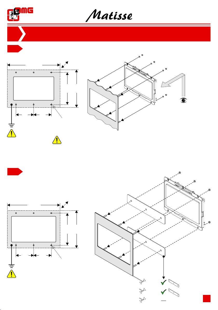
Dimensioni
Dimensions
Schermo
Screen
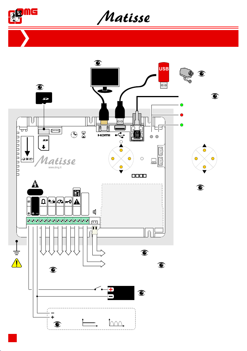
Alimentazione
Power supply
7"/10" = 24V DC ±10% * • 15,6"/18,5"/21,5" = 24V DC ±10%
Assorbimento
Power Consumpion
Stromaufnahme / Absorción
Ingressi segnalazioni
Service inputs
S1 / S2 / S3 / S4 / S5 / TRIGGER:
12÷24V DC ±10% (optoisolato / opto-isolated)
Impedenza / impedance = 3Kohm
DISPLAY
24Vdc: Max 270mA (7") • Max 330mA (10,1") • Max 150mA (Matisse CPU)
Max 600mA (15,6") • Max 700mA (18,5") • Max 800mA (21,5")
LUCE ANTIPANICO / ANTI-PANIC LIGHT
12Vdc: Max 380mA (7") • Max 440mA (10,1")
24Vdc: Max 240mA (7") • Max 260mA (10,1")
1,11,11,1 3,83,83,8 4,44,44,4
LUX
Matisse 7"7"7"
LUCE ANTIPANICO / ANTI-PANIC LIGHT
Luminosità
Brightness
4
* solo 24V eff. ±10% se si utilizza una alimentazione rettificata (non regolata)
only 24V rms ±10% if a rectified only (unregulated) voltage source is used
50 100 150
cm
100 cm
1,61,61,6 3,63,63,6 4,54,54,5
LUX
Matisse 10,1"10,1"10,1"
50 100 150
cm
100 cm
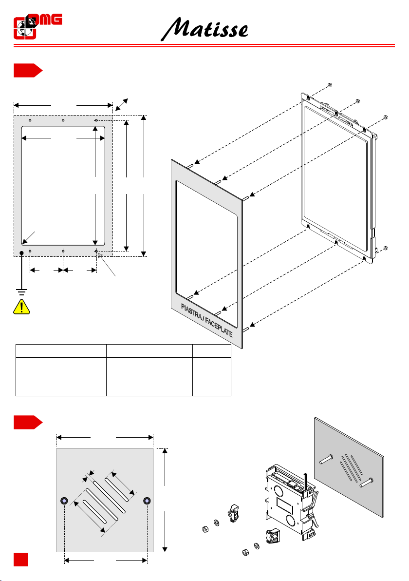
TFT 7” / CPU : 177,8x144 mm (H 20,7 mm)
TFT 10,1" : 241x169 mm (H 35,5 mm)
TFT 15,6" : 232,5x430,5 mm (H 44 mm) • TFT 15,6"VP: 271x465 mm (H 49 mm)
TFT 18,5” : 284x497,5 mm (H 49 mm)
TFT 21,5” : 324,5x564,5 mm (H 49 mm)
Temperatura di esercizio
Operating temperature
USB: +5V (max 5.25V)
HARDWARE SPECIFICATIONS:
CPU:
RAM:
STORAGE
GPU:
ON BOARD CONNECTIVITY:
AUDIO:
OTHER FEATURES:
ARM Cortex™ A9 Dual Core™, 1000 MHz,
1 GByte DDR3
300 Mbyte available internal storage + SD Card
Vivante™ GC2000 Accelerated 2D and 3D
Ethernet: 10/100/1000 Mbit/s; 1 x USB 2.0 Host; 1 HDMI 1.4
1 x Emergency/Battery supply input; Real Time Clock
4 Buttons UI navigation;
TFT 7" : 155x94 mm • 800x 480 pixel • 65.000 colors
TFT 10,1" : 222,7x125,3 mm • 1024x 600 pixel • 65.000 colors
TFT 15,6" : 193,6x334,2 mm • 1920x1080 pixel • 65.000 colors
TFT 18,5” : 230x409 mm • 1920x1080 pixel • 65.000 colors
TFT 21,5” : 268,1x476,6 mm • 1920x1080 pixel • 65.000 colors
1W on 8 Ohm Output speaker (External speaker is mandatory)
-20°C ÷ +60°C