6EU-DTC0823001–0823002
en
Dear Buyer!
Thank you for your trust in the DNIPRO M
trademark.
We are constantly working to provide
you with reliable, affordable products
with the best service.
become your indispensable assistant for
many years to come.
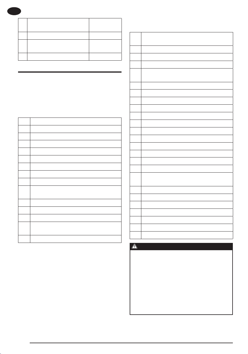
1. SAFETY INSTRUCTIONS FOR
WORKING WITH THE CORDLESS
TRIMMER
WARNING!
Read the safety warnings, instruc-
tions, illustrations, and specifica-
tions provided with this power tool.
Failure to follow all instructions may
result in electric shock, fire, and/or
serious bodily injury.
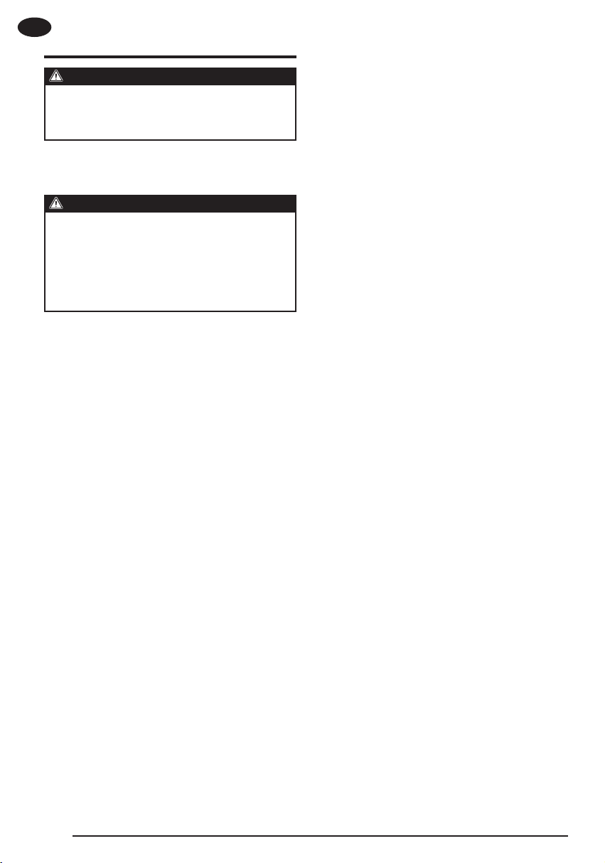
Save warnings and instructions for future
reference.
General provisions
–Familiarize yourself with the cordless
trimmer controls.
–Do not allow children, people with re-
duced mobility, or persons unfamiliar
with the original safety and operating
instructions to use the cordless trim-
mer.
–The user is responsible for accidents
that occur to other people.
Preparing for work
–Before use, check the cordless trimmer
for damage.
–Make sure that the protective cover and
limiter are properly installed.
Work
–Always wear personal protective equip-
ment when working with the cordless
trimmer.
–Do not use the cordless trimmer in bad
weather conditions, especially during
lightning.
–Do not operate the cordless trimmer
when people or animals are in the vi-
cinity.
–Do not expose the cordless trimmer to
rain or moisture. If moisture gets into
the cordless trimmer, an electric shock
may result.
–Only use the cordless trimmer in good
lighting conditions.
–Do not use the cordless trimmer with a
stopper.
–Only start the motor when you are at a
safe distance from the cutting attach-
ment.
–Clean the air vents from dirt and dust. If
the vents are very dirty, blow them out
with compressed air.
–Always disconnect the battery pack
from the cordless trimmer under the
following conditions:
–before cleaning the cordless trimmer
coil from clogging trimmings;
–before inspecting the cordless trimmer
after it has been struck by a foreign ob-
ject;
–when the cordless trimmer is left unat-
tended;
–when excessive noise and vibration oc-
cur.
Use and care of rechargeable
batteries
–Only charge the battery pack with the
–Use only the battery recommended by
the manufacturer.
–If you are not using the battery pack,
keep it away from metal objects that
could short out the terminals. Such
metal objects can include paper clips,
coins, keys, nails, screws, etc.
–
from the battery pack if not handled
properly. Rinse with water in case of
contact. If liquid gets in your eyes, get
medical attention immediately.
–-
tery pack.
–
and excessive temperatures. Exposure
may cause an explosion.
–Charge the battery pack within the tem-
perature range according to the orig-
inal safety and operating instructions.