DOLD VARIMETER IMD RN 5897/010 User manual

107.07.23 en / 755A
0274875
Your Advantages
• Preventivereandsystemprotection
• Detectionofsymmetricandasymmetricinsulationfaults
• QuickfaultlocalisationthroughselectiveearthfaultdetectiontoL+andL-
• Universalapplicationinnon-earthedAC,DC,AC/DCnetworks
uptoACmax.250VorDCmax.300V
• WithconnectionfacilityofanexternalcouplingdeviceRL5898
forvoltagesuptoAC400V/DC500Vor
RP5898forvoltagesuptoAC690V/DC1000V
• Easyadjustmentofresponsevaluesandsettingparametervia
rotationalswitchandmenudisplay
• Suitableforlargeleakagecapacitancesupto1000µF
• Optimisedreactiontimeforlargeleakagecapacitances
• Monitoringalsowithvoltage-freemains
• MeasuringcircuitL(+)/L(-)withbrokenwiredetection(canbeswitchedoff)
• ProtectiveconductorPE1/PE2withbrokenwiredetection
(can'tbeswitchedoff)
Features
• InsulationmonitoringaccordingtoIEC/EN61557-8
• Triggeroutputforinsulationfaultlocatingsystem
• 2separateadjustableresponsethresholds
(usinge.g.forpre-AlarmandAlarm)
• Settingrangeof1stresponsevalue(Pre-Alarm):20kΩ…2MΩ
• Settingrangeof2ndresponsevalue(Alarm):1kΩ…250kΩ
• 2changeovercontactsfürinsulationfailures-Pre-Alarmand-Alarm
• Energizedorde-energizedontripcanbeselectedforindicatorrelay
• Displayforindicationofmeasuredvalue,deviceparametersand
devicestatus
• Settingthemaximumleakagecapacitancetoshortentheresponsetime
• Automaticandmanualdeviceself-test
• Alarmstorageselectable
• Protectionagainstmanipulationbysealabletransparentcover
• ExternalcontrolinputforcombinedTest-/Reset-button
• 3widevoltageinputforauxiliaryvoltage
• Width52.5mm
Product Description
The insulation monitor RN 5897/010 of the VARIMETER IMD family
providesbestanduptodateinsulationmonitoringofmodernITsystems
inanoptimumandstateoftheart wayfulllingtherelevantstandards.
ThedevicecanbeusedinthemostexiblewayforAC,DCandAC/DC
systemsevenwithlargeleakagecapacitytoearth(PE).Theadjustmentof
thesettingvaluesissimpleanduserfriendlydoneon2rotaryswitcheson
thefrontofthedevice.ViadisplayandLEDsthemeasuredvalue,device
parametersanddevicestatusareindicatedeasytoread.Withasealable
transparentcoverthedeviceisprotectetagainstmanipulation.
Approvals and Markings
Applications
Insulationmonitoringof:
• Non-earthedAC,DC,AC/DCnetworks
• UPSsystems
• Networkswithfrequencyinverters
• Batterynetworks
• Networkswithdirectcurrentdrives
• Hybridandbattery-poweredvehicles
• Mobilegeneratorsets
Monitoring Technique
VARIMETER IMD
Insulation monitor
RN 5897/010
Function Diagram
Manual reset
Alarm
Alarm Pre-Alarm Pre-Alarm
Hysteresis function
Reset
21-24
21-24
21-24
21-24
11-14
11-14
11-14
11-14
11-12
11-12
11-12
11-12
Earth fault
E
R
A
RpA
R
21-22
21-22
21-22
21-22
t
t
Open circuit operation
De-energized on trip
UH
M11593
RN5897/010 RP5898
Couplingdevices
RL5898
AC/DC
Canada/USA 1)RN5897only
Translation
of the original instructions
AllTechnicalDatainthislistrelatetothestateatthemomentofedition.Wereservetheright
fortechnicalimprovementsandchangesatanytime.

207.07.23 en / 755A
ThedeviceissuppliedwithDCauxiliaryvoltageviaterminalsA1(+)/A2.
Switchingontheauxiliaryvoltage(Power-On)is followedbyaninternal
self-testfor12sec(see„Devicetestfunctions“).Thetestprocessisvisible
inthedisplay.Afterthis,measurementoftheinsulationresistanceinthe
measuring circuits begins and the the colour of the backlight changes
intogreen.
Measuring circuit
(Insulation measurement between terminals L(+) / L(-) and PE1/PE2)
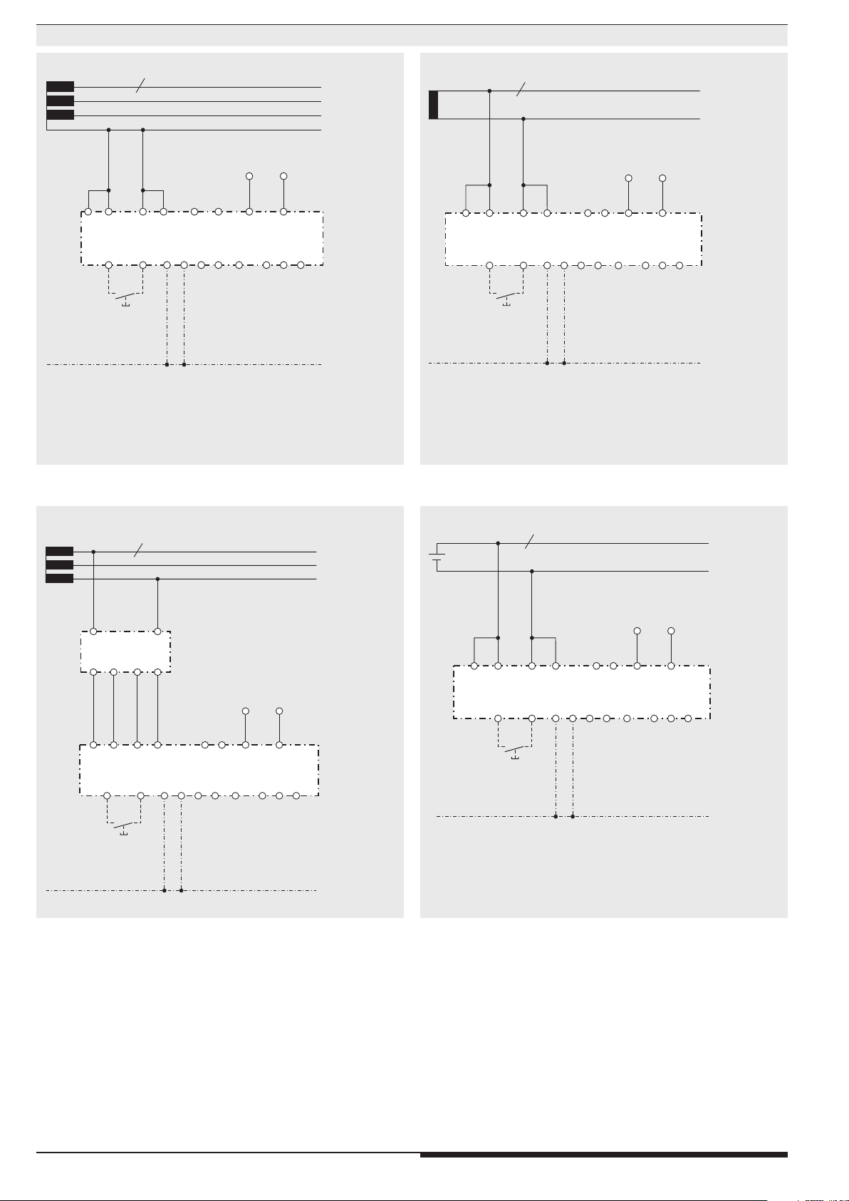
TheinsulationmonitorRN5897/010canbeoperatedeitherwithorwithout
couplingdevice.Max.mainsvoltageandconnectiondiagramshaveto
beobserved!
Iftheinsulationmonitorisoperatedwithoutcouplingdevicetheterminals
L(+)andL(-)havetobeconnecteddirectlytothevoltagesystemtobe
monitored.andtheterminalsVSG1/L(+)andVSG2/L(-)eachhavetobe
bridged(seealsooperationwithcouplingdevice).
Abrokenwiredetectionthatcanbedisabledprovidesafaultsignalifboth
terminalsL(+)andL(-)arenotlinkedbytheconnectednetwork.
Thetypeofnetwork(AC,DC,3NAC)hastobeselected.
AlsotheterminalsPE1andPE2havetobeconnectedwith2separate
wirestotheprotectiveearth.Aninterruptionofawirealsocausesafault
signal(seesection”Behavioronfaultyconnection”).Themonitoringof
thePEconnectioncannotbede-activated.
Tomeasuretheinsulationresistanceanactivemeasuringvoltagewith
changing polarity is connected between L(+)/L(-) and PE1/PE2.The
momentarypolarityofthemeasuringcycleisshownonthedisplayby
2 c u r s e r s e g m e n t s ( „ M P +“ f o rp o s i t i v e p h a s e a n d„ M P - “ f o rn e g a t i v e p h a s e ) .
Thedurationofthepositiveandnegativemeasuringphasedependson
t he se t t in go ft h em a x .l ea ka ge ca pa c it y( „ CE[µF]“inprogrammingmode),
theactualleakagecapacityofthemonitoredsystemandinDCsystems
alsoonthelevelanddurationofpossiblevoltagevariations.Thisallows
acorrectandfastmeasurementindifferentnetworkconditions.
Attheendofameasuringcycletheactualinsulationresistanceisproduced
a n d i n d i c a t e d . T h e a c t u a l v a l u e i s s h o w n o n t h e d i s p l a y. T h e r e l a y s f o r a l a r m
K1andpre-alarmK2switchwhendroppingundertheadjustedresponse
values.Inadditionthebacklightofthedisplaychangestoorangecolor
onpre-alarmortoredcoloronalarm.Anasymmetricearthfaulteitherto
„+“or„-“isalsoindicatedonthedisplay(onlyinDC-systems,orwitha
faultontheDC-sideofasystem).
Manual reset of fault message
Usingthedisplaymenuinprogrammingmode,themanualresetfunction
forinsulationfailures canbe selected. If manual resetisactivatedthe
insulationfaultsignalsofthemeasuringcircuitarestoredwhendropping
undertheadjustedresponsevaluesalsoiftheinsulationresistancegoes
backtohealthystate.Theminimumvalueisstoredandcanbeshownon
thedisplay.Pressingthe„Reset“button(2s)onthefrontside,thealarm
signal and the stored minimum value are reset if the actual insulation
resistanceisinhealthystate.
Indicator relay for insulation fault signal
FortheindicatorrelaysK1(contacts11-12-14,foralarm)andK2(contacts
21-22-24,forpre-alarm)thefunctioncanbesetinprogrammingmodeto
energizedontriporde-energizedontripwhentheinsulationresistance
dropsbelowtheadjustedresponsevalue.
T h e s t a tu s o f t h e i n d i c a t o rr e l a y s i s s h ow n o n t h ed i s p l ay w i t h t h et w o c u r s o r
segments"K1"and"K2".Whentherelayisenergized,thecorresponding
curserlightsup.
Trigger output for insulation fault locating system
Thereisanadditionaltriggeroutputforaninsulationfaultdetectionsystem
ontheinsulationmonitorRN5897/010.
Thistriggeroutput(Y1-Y2)can becoupled withthetriggerinputY1-Y2
of RR 5886 to initiate automatic fault location with the insulation fault
locatingsystem,consistingofRR5886andRR5887.Thetriggeroutputis
activatedwhenthemeasuringvaluedropsunderthealarmresponsevalue
(RE<RA).Aslongasitstaysundertheresponsevalueoranalarmis
stored,thetriggeroutputY1-Y2remainsactive.
Broken wire detection
Asdescribedinsection"Measuringcircut",themeasuringcircuitsL(+)/L(-)
andtheprotectiveconductorsPE1/PE2areconstantlymonitoredforwire
breaks–notonlyatPower-Onoramanualoroccasionalautomatictest.
The response time of monitoring is only a few seconds. Broken wire
detection between L(+) and L(-) is performed via coupled alternating
voltage. This alternating voltage is short-circuited if the terminals are
connectedtotheconnectedmainsatlow-resistance.Thedevicedetects
thatthemainstobemonitoredisproperlyconnected.
S i n c e t h i s b r o k e n w i r e d e t e c t i o n i s c a r r i e d o u t w i t h a l t e r n a t i n g v o l t a g e , l a r g e
c a p a c i t a n c e s s h o u l d b e a v o i d e d b e t w e e n L( +) a n d L ( - ) , s i n c e t h e c a p a c i t i v e
reactanceofthesecapacitancesalsoshort-circuitsthisalternatingvoltage.
ThedevicewouldnolongerdetectaconnectionfaultonL(+)/L(-).
Especiallyparallellinesshouldbepreventedoverlargerdistances.
I fl a r g er c a pa c i t a nc e s b et w e e nL (+ ) / L ( - ) c an n o tb e av o i d e do ri f t he c o u pl e d
alternatingvoltageinterfereswiththesystem,thebrokenwiredetectioncan
bede-activatedusingthedisplaymenuinprogrammingmode.Monitoring
deactivated,monitoringonlyduringdevicetestorcontinuousmonitoring
(every2minutesfor10sec)arethepossibleoptions.Ifthebrokenwire
detectiononL(+)/L(-)isde-activatednoACvoltageisinjected.
ThebrokenwiredetectiononPE1/PE2cannotbede-activated.
Device test functions
Principally,2differenttestfunctionsareimplemented:The"self-test"and
the"expandedtest":
Theself-testofthedeviceisperfor medautomaticallyaf terPower-Onand
eve r yf ullo per at in gh ou rs.I tc an al so be tr ig ger ed man ua ll yata nyt im eb y
pressingthe"Test"buttonatthedevicefrontfor2sec.
W it ht hes el f-t es t,c on tr ar y tot he ex pa nd edt es t,t hes ta tu so ft h eI nd ic ato r
relaysisnotaffected;thesequenceisasfollows:
Thedisplaybacklightcolourchangesintoorange.Forapprox.2sallp ixels
andsegmentsoftheLCDareshown.Afterthatthetext“Test1”comesup
andthemeasuringpulseisswitchedforapprox.5stonegativetestphase.
Thepolarityofthetestvoltageisalsoindicatedonthedisplaybycurser
segments.Withinthese5stheinternalmeasuringcircuitischeckedfor
failures.Thenthemeasuringpulseisswitchedforapprox.5stopositive
testphaseandmoreinternalteststakeplace.Ifnofailuresturnedupand
hadbeenrecognized,themeasurementcontinuous.Theextendedtest
procedureisstartedwhenduringorattheendoftheabovedescribed
12sself-testthetestbuttonispressedagainfor2s.
Thesequenceissimilartotheself-test(2measuringphasesof5seach)
butinadditiontheoutputrelaysgoinalarmstated.Thedisplayshows
“ Te s t 2 ”. T h e ex t e n d e d t e s t c a n b e n i s h e d a f t e r t h e r s t c o m p l e t e s e q u e n c e
(approx.10sec)bypressingthe"reset"buttonfor2seconds.Thedevice
startstheinsulationmonitoringagain.
Test signal
1)
Reset signal
2)
Relay state K1 and K2
Measuring voltage
Positive
Alarm
No Alarm
Insulation
measurement
Insulation
measurement
Insulation
measurement
3)
4)
Self test (Test 1)
Duration: approx. 12s
Self test (Test 1)
Duration: approx. 12s
Duration: approx. 10s
Continuous extended
test (Test 2)
Negative
M12462
U
t
1)Testsignal:ButtonTest>2sorX1/X2<3s
2)Resetsignal:ButtonReset>2sorX1/X2>3s
3)Toinitiatetheextendedtest(Test2)thetestsignalmustbeoperated
withintheselftest(Test1)again.
4)Theresetsignalhasherenofunction,astherstcompletesequence
ofextendedtest(Test2)isnotnished.
FunctionFunction

307.07.23 en / 755A
Behaviour with internal device faults
Ifinternaldevicefaultsweredetectedduringthetestfunction,thedisplay
backlightchangesintoredandanerrormessages(failurecode:„Int.1“)
isindicated.TheindicatorrelaysK1andK2switchtothealarmstate.
Behavior on faulty connection
WhendetectingbrokenwireonterminalsL(+)/L(-),themeasurementis
disabled.Thereactiontimecouldbeupto2min.Themonitoringrelays
K1andK2goinalarmstate,thebacklightchangestored.Thedisplay
showsthefaultmessage„L+/L-“.Afterremovingtheinterruptionthefaultis
automaticallyreset(max.reactiontimeupto2min)andthemeasurement
oftheinsulationresistanceiscontinued.
Stored alarm values remain stored. An interruption of the protective
earthconnectionsPE1/PE2causesthesamereactionasinterruptingthe
measuringcircuit,onlythedisplayshows„PE1-PE2“.
External control input
To terminals X1/X2 an external combined Test-/Reset button can be
connected.IftheterminalsX1/X2arebridgedforapprox..1sthetestmode
isstarted.Thishasthesamefunctionaspressingtheinternaltestbutton.
WhenbridgingX1/X2for>3s,astoredalarmwillbereset.Thishasthe
samefunctionaspressingtheinternalresetbutton.
Connection of an external coupling device
AnexternalcouplingdeviceRP5898/010canbeconnectedtoextendthe
inputvoltagerangeofthemonitoredvoltagesystemonRN5897/
010
.The
terminalswiththesamelegendoftheinsulationmonitorandthecoupling
d e v i c e R L 5 8 9 8 o r R P 5 8 9 8 ( V S G 1, V S G 2 , L ( + ) , L ( - ) ) a r e c o n n e c t e d t o g e t h e r .
ThenetworktobemonitoredisconnectedtoterminalsL1(+)undL2(-)on
the couplingdevice.Using the displaymenu in programming mode the
connectionofthecouplingdevicehastobeselectedandactivated.The
brokenwiredetectionisactiveontheterminalsL1(+)/L2(-)onthecoupling
device. A broken wire between coupling device and insulation monitor
cannotbedetectedimmediatelybutthemeasuredvaluesoninterruption
of1or2wiresbetweencouplingdeviceandinsulationmonitoraremuch
lowerastherealvalues,whichwillcauseanearlyresponseofthedevice.
Programming/setting of parameters/set-up of the insulation monitor
Theresponsevaluesforalarmandpre-alarmcanbeadjustedvia2rotary
switches„R
A
“ a n d „ R
pA
“onthefrontofthedevice.Newsettingareimmediately
activeanddonotrequirearestartoftheunit.Moresettingscanbedone
withthe3buttonsandthedisplaymenuinprogrammingmode.Tostartthe
programmingmode,thebutton„Set/ESC“hastobepressedforapprox.
2s.Toavoidunauthorizedmanipulation,thisbuttonaswellastherotary
switches„R
A
“ a n d „ R
pA
“ a r el o c a t e d b e h i n d as e a l a b l e t r a n s p a r e n tc o ve r. W h e n
thedevicechangestoprogrammingmode,themeasurementisstopped,
thedisplaybacklightchangestoorangecolorandtherstparameteris
displayed.Toscrollthedifferentparameters,thebutton„Set/ESC“hasto
bepressedshor t.Withthe2scrollbuttons(Scroll-Up„
“andScroll-Down
„
“)thesettingscanbemodied.
Therstparameteristhebrokenwiredetectioninthemeasuringcircuit
„BrWiD“.Possiblesettingarecontinuouslyon(„on“),continuouslyoff(„oFF“)
oronlyactiveduringself-test.Thedefaultis„on“.
T h e s e c o n d p a r a m e t er i s al a r m m e m o r y „ M e m .“ .H e r e a r e 2 o pt i o n s av a i l a b l e
manualreset(„on“)undautoreset(„oFF“).Thedefaultvalueis„oFF“.
The third parameter is the relay operation principle „Rel.“ Settings are:
de-energized on trip („n.c.“) and energized on trip („n.o.“). The default
valueis„n.c.“.
Thefourthparameteristhetypeofnetworkconnection„Net“.Selection
areACNetwork(„Ac“),DC-Network(„dc“)or3NAC-Network(„3nAc“).The
defaultvalueis„Ac“.
The fth parameter ist the setting oft the maximum leakage capacity
(„C
E
[µF]“).Thiscanbeadjustedto30µF(„30“),100µF(„100“),300µF
(„300“)and1000µF(„1000“).Thedefaultvalueis„30“.
Thedeviceallowtheconnectionofacouplingdevice,thesixthparameter
activates(„on“)orde-activates(„oFF“)thecouplingdevice.
Theleavetheprogrammingmodethebutton„Set/ESC“hastobepressed
for2s.Thesettingswillbeactivatedandstoredpermanently.Afterthatthe
devicemakesarestartsimilartopoweron.
Function
Connection Terminals
Terminal designation Signal description
A1(+),A2 AuxiliarxvoltageACorDC
L(+),L(-),VSG1,VSG2 Connectionformeasuringciruitor
Connectionforcouplingdevice
PE1,PE2 Connectionforprotectiveconductor
X1,X2 Controlinput(combinedexternal
Test-andReset-input)
Y1,Y2 Alarmtriggeroutputforinsulationfault
locatingsystem
11,12,14 AlarmsignalrelayK1(1changeovercontact)
21,22,24 PrewarningsignalrelayK2(1changeover
contact)
Circuit Diagram
Default-Setting of Parameters
Nr. Parameter Default-Set
1
Brokenwiredetectinmeasuringcircuit
“BrokenWireDetect” on
2
Storinginsulationfaultmessage
“Memory” off
3
Switchingmodeofoutputrelays
“Relay”
n.c.(normallyclosed)
de-energizedontrip
4
Powersupplytype
“Net” AC
5
Max.linecapacitance
“CE[µF]” 30
6Ext.
couplingdevice
“VSG” off
X1 X2
11 12 14 21 22 24 PE1 PE2
A2
A1(+)
M11455_a
L(+)VSG1 VSG2
L(-)
22
12
L(+) L(-)
24
14
21
PE2
11
PE1
UH
Y1 Y2

407.07.23 en / 755A
Indicators Indicators
Thecolourofthebacklightindicatestheoperatingstatusofthedevice.
Off: Noauxiliaryvoltageconnected
Green: Normaloperation(Insulationresistanceinhealthystate)
Red: Alarm(measuredvaluebelowalarmresponsevalue,
devicefailure,connectionfailure)
Orange: Warning(measuredvaluebelowpre-alarmresponsevalue,
testmode,Parameterset-upmode)
Actual value display
The actual insulation resistance „RE [kΩ]“ is displayed. If the actual
value is RE < 10 kΩ, the value in kohm is displayed with 1 decimal
place. With values 10 kΩ≤R
E < 500 kΩ the display shows the value
without decimal place, with values 500 kΩ≤R
E < 1 MΩ the value is
rounded to 10 kΩ. Insulation resistance values 1 MΩ≤R
E < 2 MΩ
are displayed in MOhm with one decimal place. If the resistance is
RE>2MΩthedisplayindicates----showingthevalueishigherthe2MΩ.
In a DC Network an asymmetric insulation resistance to „+“ or „-“ is
indicatedbydisplaying„RE+[kΩ]“or„RE-[kΩ]“
Bypressingthescrollbuttons(Scroll-Up„“undScroll-Down„“)more
measuredvaluescanbeshown.Anothervalueisthe mainsvoltageon
L(+)/L(-).Thisisindicatedwith„UN[VAC]“or„UN[VDC]“inVdependingon
thetypeofnetworkandvoltage.Iftheunitisconnectedsinglepoletoa
3NACnetworkthemainsvoltagecannotbemeasured.Withthissetting
the voltage value is not displayed. When manual reset is selected, the
displayshowstheminimumstoredvalueofthe resistance„RM[MΩ]“or
„RM[kΩ]“afterthevaluedroppedbelowtheresponsevaluealsowhenthe
valuegoesbacktohealthystate.Thestoredminimumvaluewillonlybe
resetwhenacknowledgingthestoredAlarmsignal(withtheresetbutton).
Alsothermwareversioncanbedisplayed.
Positivemeasurement
phaseactive(MP+)
Negativemeasurement
phaseactive(MP-)
Pre-Alarmmonitoring
relayK2energized
Alarmmonitoringrelay
K1energized
Connection
measuring ciruit
or
Coupling device Auxiliary
voltage
Trigger
output
M11597_c
Indicator relay
alarm and pre-alarm
Protective
conductor
External
control input
RN5897/010

507.07.23 en / 755A
Indicators
Display-Indication Measuring- resp. display value
InsulatingresistanceinkΩresp.MΩ
(„----“compliesRE≥2MΩ)
AsymmetricalinsulatingresistanceinkΩ
againstL+orL-atDC-mains
MeasuredmainsvoltageinV
atAC-orDC-mains
(„----“indicatesinvalidvoltagevalueor
voltage<5V)
Storedmin.insulatingresistance
inkΩresp.MΩ
Latestrmware-version
Display-Indication Test function
Display-Test
Selftesting
(measuringswitching,measuringvoltage,
internaltests)
AdvancedTest
(additionalcontrolofindicatorrelay)
Error Indication
Display-Indication Failure cause Failure recovery
Brokenwiredetection
onL(+)/L(-).
Check
measuringcircuit
L(+)andL(-)
Brokenwiredetection
onPE1/PE2.
Check
protectiveconductor
connections
PE1andPE2
Internalfailure
detectedin
testmode
Presstestbuttonagain
orrestarttheunitby
interruptingtheauxiliary
supplytemporarily.
Ifthefaultremains
permanent,senddevice
backtomanufacturerfor
examination.
Faultycalibration
valuesdetectedin
devicememory.
Senddeviceback
tomanufacturerfor
recalobrationand
examination.

607.07.23 en / 755A
Notes
WARNING
Risk of electrocution!
Danger to life or risk of serious injuries.
• Disconnectthesystemanddevicefromthepowersupplyandensure
theyremaindisconnectedduringelectricalinstallation.
• Thedisplayofthevoltageisnotinrealtime.TheValueonthedisplayis
updatedattheendofameasuringcycle.Determinevoltagefreestatus
byusingappropriateinstruments!
• TheterminalsofthecontrolinputX1-X2havenogalvanicseparationto
themeasuringcircuitL(+)-L(-)andareelectricallyconnectedtogether,
th ereforet heyhavetobeco nt ro ll edbyvo ltfre ec ontac tsorbri dge.Th es e
contactsorebridgesmustprovideasufcientseparationdependingon
themainsvoltageonL(+)-L(-).
• PleasedonotconnectexternalvoltagetoterminalsX1/X2.Thecontrol
mustonlybemadebybridgingX1andX2.
• Thecouplingunit
RL5898orRP5898
mustonlybeusedinconjunction
withtheRP5897/010onavoltagesystemandnotjustbyitself.
!
Attention!
• Beforecheckinginsulationandvoltage,disconnectthemonitoringdevice
RN5897fromthepowersource!
• Inonevoltagesystemonlyoneinsulationmonitorcanbeused.Thishas
tobeobservedwheninterconnectingtwoseparatesystems..
• DeviceterminalsPE1andPE2mustalwaysbeconnectedviaseparate
linestodifferentterminalpointsoftheprotective-conductorsystem.
• ThedevicemustnotbeoperatedwithoutPE1/PE2connection!
nfo
Attention!
• T h e m a i n m e a s ur i n g c i r c u i t c a n b e c o n n e c t e d w i t h i t st e r m i n a l s L (+ ) a n d
L(-)bothtotheDCandalsoACsideofamixednet work;itisdonemost
practicallywheretheprimaryincomingpowersupplytakesplacee.g.
withbatterynetworkswithconnectedinvertersontheDCside,with
Generators/TransformerswithconnectedRectiersorinvertersonthe
AC-side.Tomonitora3NACsystemthedevicecanbeconnectedsingle
pole,(L(+)andL(-)arebridged,totheneutralofthe3p4wsystem.The3
phaseshavealow-ohmic(approx.3–5Ω)connectionviathetransformer
windingssoalsoinsulationfailuresofthenotdirectlyconnectedphases
aredetected.Viathedisplaymenuinprogrammingmodethecorrect
typeofnetworkneedstobeselected(see„ConnectionExamples“).
• IfamonitoredACsystemincludesgalvanicallyconnectedDCcircuits
(e.g. via a rectier), an insulation failure on the DC side can only
be detected correctly, when a current of > 10 mA can ow via the
semiconductorconnections.
• IfamonitoredDCsystemincludesgalvanicallyconnectedACcircuits
(e.g. via an inverter), an insulation failure on the AC side can only
be detected correctly, when a current of > 10 mA can ow via the
semiconductorconnections.
• ThemeasuringcircuitoftheRN5897/010aredesignedforleakage
capacitiesupto1000µF.Themeasurementoftheinsulationresistance
willnotbeinuencedbutforthemeasuringphaseslongertimeperiods
arenecessaryaswithsmallercapacities.Ifthemax.possibleleakage
capacityisknown,thedevicecanbeadjustedtotherequiredlower
level,whichwillreducetheresponsetimeandmeasurementtime.
• ThetriggeroutputY1/Y2atRN5897/010isgalvanicseparatedfromthe
restofthecircuit.ItdeterminedtobeconnectedtoaDOLDinsulation
fault location system RR5886 and RR5887. Please do not connect
externalvoltages.

707.07.23 en / 755A
Running chart
Press button
Scroll Up „▲“
Press button
Scroll Down „ ▼“
Press button
„Set/ESC“ >2s
Set parameters
Parameter 1:
Broken wire detect in
measuring circuit
„BrWiD“
(Broken Wire Detect)
Default: „on“
Parameter 2:
Storing insulation fault
message
„Mem.“
(Memory)
Default:
„
oFF“
Parameter 3:
Switching mode of
output relays
„Rel.“
(Relay)
Default:
„
n.c.“
Parameter 4:
Power supply type
„Net“
Default: „Ac“
Parameter 5:
Max. line capacitance
„C E[µF]“
Default: „30“
Parameter 6:
Ext. coupling device
„VSG“
Default: „oFF“
Parameter 1:
Broken wire detect in
measuring circuit
„BrWiD“
(Broken Wire Detect)
„oFF“
Parameter 1:
Broken wire detect in
measuring circuit
„BrWiD“
(Broken Wire Detect)
„tESt“
Parameter 2:
Storing insulation fault
message
„Mem.“
(Memory)
„
on“
Parameter 3:
Switching mode of
output relays
„Rel.“
(Relay)
„
n.o.“
Parameter 4:
Power supply type
„Net“
„dc“
Parameter 4:
Power supply type
„Net“
„3nAc“
Parameter 5:
Max. line capacitance
„C E[µF]“
„100“
Parameter 5:
Max. line capacitance
„C E[µF]“
„300“
Parameter 5:
Max. line capacitance
„C E[µF]“
„1000“
Parameter 6:
Ext. coupling device
„VSG“
„on“
Press button
„Set/ESC“
Press button
„Set/ESC“ >2s
End of programming

807.07.23 en / 755A
Nominal consumption:
DC12V,24V,48V: Max.3W
AC230V: Max.3.5VA
Control input X1/X2 for combinied external Test-/Reset-Taste
Current flow: Approx.3mA
No-load operation voltage
X1 to X2: Approx.12V
Permissible wire length: <50m
Activation time for test signal:Approx.1s
Activation time for reset signal:>3s
Outputs
Indicator contact: 2x1changeovercontactforAlarm(K1)
andPre-Alarm(K2)
energizedorde-energizedontrip
(programmable)
Thermal current Ith: 4A
Switching capacity
toAC15:
NOcontact: 5A/AC230V IEC/EN60947-5-1
NCcontact: 2A/AC230V IEC/EN60947-5-1
ToDC13: 2A/DC24V IEC/EN60947-5-1
Electrical life
at5A,AC230V: 1x10⁵switchingcycles
Short circuit strength
max. fuse rating: 4AgG/gL IEC/EN60947-5-1
Mechanical life: 50x106switchingcycles
General Data
Operating mode: Continuousoperation
Temperature range
Operation: -30...+60°C
(atrange0…-30°Climited
functionoftheLCDdisplaye)
Storage: -30...+70°C
Altitude:≤2000m IEC60664-1
Clearance and creepage
distances
Ratedinsulationvoltage: 300V
Overvoltagecategory: III
Ratedimpulsvoltage/
pollutiondegree: IEC60664-1
MeasuringcircuitL(+)/L(-)to
auxiliaryvoltageA1(+)/A2and
indicatorrelaycontactsK1,K2and
triggeroutputY1/Y2: 4kV/2
AuxiliaryvoltageA1(+)/A2to
indicatorrelaycontactsK1,K2and
triggeroutputY1/Y2: 4kV/2
IndicatorrelaycontactK1to
indicatorrelaycontactsK2: 4kV/2
TriggeroutputY1/Y2to
indicatorrelaycontactsK1,K2: 4kV/2
Insulationtestvoltage
Routinetest: AC2.5kV;1s
EMC IEC/EN61326-2-4
Electrostaticdischarge(ESD): 8kV(air) IEC/EN61000-4-2
HFirradiation:
80MHz…1GHz: 20V/m IEC/EN61000-4-3
1GHz…2.7GHz: 10V/m IEC/EN61000-4-3
Fasttransients: 2kV IEC/EN61000-4-4
Surgevoltage
between
wiresforpowersupply: 1kV IEC/EN61000-4-5
Betweenwireandground: 2kV IEC/EN61000-4-5
HF-wireguided: 20V IEC/EN61000-4-6
Interferencesuppression: LimitvalueclasseB EN55011
Degree of protection
Housing: IP30(notsealed) IEC/EN60529
IP40(sealedwith
sealwire50/30) IEC/EN60529
Theunitmustbe
disconnectedfromthe
powersupplybefore
thesealisapplied
Terminals: IP20 IEC/EN60529
Housing: ThermpolasticwithV0behaviour
accordingtoULsubject94
Measuring ciruit L(+)/L(-) to PE1/PE2 (without coupling device)
Nominal voltage UN: AC/DC0...230V
Max. voltage range UN: AC0...250V
DC0...300V
Frequency range: DCor16...1000Hz
Max. line capacitance: 1000µF
Internal resistance (AC / DC): >90kΩ
Measuring voltage: Approx.±90V
Max. mesured current (RE= 0):<1.10mA
Response inaccuracy:±15%±1.5kΩ IEC61557-8
Response value hysteresis: Approx.+25%;min.+1kΩ
On delay
atCE=1µF,
REof∞to0.5*responsevalue: <30s
Measuring time:
atCE=1…1000µF,
REfrom∞to1000kΩ,
REfrom∞to100kΩ,
REfrom∞to1kΩ: Seecharacteristics
Response values
Pre-warning(„RpA“):
kΩ:20 30 50 100 250 500 1000 2000
Alarm(„RA“)
kΩ:1 2 10 20 50 100 150 250
Eachadjustableviarotationalswitches
Response value broken
wire detection L(+)/L(-): >Approx.90kΩ
Response value broken
wire detection PE1/PE2: >Approx.0.5kΩ
Meas. ciruit L1(+)/L2(-) to PE1/PE2 (with coupling device RL / RP 5898)
RL 5898 RP 5898
Nominal voltage UN:AC0...400V AC0...690V
DC0...500V DC0...1000V
Max. max. voltage range UN:AC0...440V AC0...760V
DC0...550V DC0...1100V
Frequency range: DCor16...1000Hz
Max. line capacitance: 1000µF
Internal resistance (AC / DC): >240kΩ
Meas voltage: Approx.±90V
Max. mesured current (RE= 0):<0.40mA
Response inaccuracy:±15%±1.5kΩ IEC61557-8
Response value hysteresis: Approx.+25%;min.+1kΩ
On delay
atCE=1µF,
REof∞to0.5*responsevalue: <30s
Measuring time:
atCE=1…1000µF,
REfrom∞to1000kΩ,
REfrom∞to100kΩ,
REfrom∞to1kΩ: Seecharacteristics
Response values
Pre-warning(„RpA“):
kΩ:20 30 50 100 250 500 1000 2000
Alarm(„RA“)
kΩ:1 2 10 20 50 100 150 250
Eachadjustableviarotationalswitches
Response value broken
wire detection L1(+)/L2(-): >Approx.500kΩ
Response value broken
wire detection PE1/PE2: >Approx.0.5kΩ
Max. wire length
between insulation monitor
and coupling device: <0.5m
Auxiliary voltage input A1(+)/A2
Nom. Voltage Voltage range Frequency range
AC/DC24...60V AC19...68V 45…400Hz;DC48%W*)
DC16...96V W*)≤5%
AC/DC85...230V AC68...276V 45…400Hz;DC48%W*)
DC67...300V W*)≤5%
DC12...24V DC9.6...30V W*)≤5%
*)W=Permittedresidualrippleofauxiliarysupply
Technical Data Technical Data

907.07.23 en / 755A
Vibration resistance: Amplitude0.35mm,
Frequency10...55Hz,IEC/EN60068-2-6
frequency2...13.2Hz,13.2...100Hz,
acceleration±0.7gn IEC/EN60068-2-6
Shock resistance: 10gn/11ms,3pulsesIEC/EN60068-2-27
Climate resistance: 30/060/04 IEC/EN60068-1
Terminal designation: EN50005
Wire connection DIN46228-1/-2/-3/-4
Crosssection: 0.5...4mm²(AWG20-10)solidor
0.5...4mm²(AWG20-10)
strandedwirewithoutferrules
0.5...2.5mm²(AWG20-10)
strandedwirewithferrules
Strippinglength: 6.5mm
Wire fixing: Cross-headscrew/M3boxterminals
Fixing torque: 0.5Nm
Mounting: DINrail IEC/EN60715
Weight: Approx.205g
Dimensions
Width x height x depth: 52.2x90x71mm
Technical Data Standard Types
RN5897.12/010/61 DC12...24V
Articlenumber: 0067251
• Auxiliaryvoltage: DC12...24V
RN5897.12/010/61 AC/DC24…60V
Articlenumber: 0066940
• Auxiliaryvoltage: AC/DC24…60V
RN5897.12/010/61 AC/DC85…230V
Articlenumber: 0066941
• Auxiliaryvoltage: AC/DC85…230V
• Outputs: 1changeovercontactforpre-warning
1changeovercontactforalarm
• Settingrangepre-warning: 20kΩ…2MΩ
• Settingrangealarm: 1kΩ…250kΩ
• Triggeroutputforinsulationfaultlocatingsystem
• WithconnectionfacilityofacouplingdeviceRL5898orRP5898
• Adjustablelinecapacitance
• Energizedorde-energizedontrip
• Selectionoftypeofnetwork
• Width: 52.5mm
Ordering Example for variants
RN5897.12
/010/61AC/DC24…60V1kΩ-250kΩ20kΩ-2MΩ
SettingrangePre-warning
Settingrangealarm
Auxiliaryvoltage
ULapproval
Variant,ifrequired
Contacts
Type
RN5897.12/060: Withdisablethemeasuringfunction
UsingtheexternalcontrolinputX1/X2the
measuringfunctionoftheRN5897/060
canbedisabled.Thiscouldbeusedwhen
severalisolatedvoltagesystemswith
individualinsulationmonitorsneedtobe
coupled.
Themeasuringvoltageissetto-90V
(negativemeasuringphase)andthe
evaluationofthemeasurementis
stopped.Thestatusoftheoutputrelaysis
frozenandnotchangedanymore.Ifthe
measurementisdisabledthecolourofthe
displaychangestoorangeandthetext
"Stop!"isdisplayed.
Pleasebeaware,onlytheevaluationof
themeasurementisstoppedandthe
measuringpulseisinterrupted!Ahigh
resistivedisconnectiontoPEdoesnot
takeplace(seeTechnicalDatainternal
resistance).
Activation time t for stop
of the measuring function: t>10s
Meas. ciruit L1(+)/L2(-) to PE1/PE2 (with coupling device RL / RP 5898)
RL 5898 RP 5898
Max. voltage range UN:AC0...400V AC0...600V
DC0...500V DC0...600V
Output voltage at
L(+)/L(-), VSG1/VSG2: Max.AC/DC230V
Switching capacity: PilotdutyC300,R300
5A250Vac
2A30Vdc
Wire connection: 60°C/75°Ccopperconductorsonly
Torque0.5Nm
Test specification: ANSI/UL60947-1,5thEdition
ANSI/UL60947-5-1,3rdEdition
CAN/CSA-C22.2No.60947-1-13,
2ndEdition
CAN/CSA-C22.2No.60947-5-1-14,
1stEdition
nfo
Technical data that is not stated in the UL-Data, can be found
in the technical data section.
UL-Data
Vibration and
shock resistance: Category1,ClassB IEC/EN61373
Service temperature classes:OT1compliant
Protective coating of the PCB: No
Classification to DIN EN 50155
Switching capacity
ToAC15
NOcontact: 3A/AC230V
NCcontact: 1A/AC230V
nfo
Technical data that is not stated in the CCC-Data,can be found
in the technical data section.
CCC-Data

10 07.07.23 en / 755A
Connection Example
*1)AuxiliaryvoltageUH(A1(+)/A2)canalsobesourcedfromthemonitoredvoltagesystem.
Thevoltagerangeoftheauxiliarysupplyhastobetakenintoaccount.
*2) ControlinputX1/X2forexternalcombinedTest-/Reset-button:
• Controlapprox.1s: Testfunction
• Control>3s: Resetfunction
L(+)VSG1
RN5897/010
X1
External combined
Test/Reset button
L(-) VSG2
X2 11PE1 12PE2 14 21 22 24
M11619
*2)
A1(+)Y1 Y2 A2
UH
*1)
PE
L+
Ungrounded DC network
DC 0...300V
L-
UN
Setting of type of network
DC
coupling device:
OFF
:
External
VSG1
VSG1
L(+)
L(+)
L(-)
L(-)
PE
RN5897/010
X1
External combined
Test/Reset button
VSG2
VSG2
X2 11PE1 12PE2 14 21 22 24
M11625_a
*2)
A1(+)Y1 Y2 A2
UH
*1)
L1
L2
L3 UN
L1(+) L2(-) Setting of type of network:
AC
External coupling device:
ON
RL5898
RP5898
Ungrounded mains
RL5898: 3 AC 0...440V 16...1000Hz
RP5898: 3 AC 0...760V 16...1000Hz
L1
Single phase mains, isolated from earth
AC 0...250V 16...1000Hz
L2
L(+)VSG1
RN5897/010
X1
External combined
Test/Reset button
L(-) VSG2
X2 11PE1 12PE2 14 21 22 24
M11617
*2)
A1(+)Y1 Y2 A2
UH
*1)
UN
Setting of type of network
AC
coupling device:
OFF
:
External
L1
Ungrounded mains
3/N AC 400V/230V 16...1000Hz
L2
L3
N
RN5897/010
X1
External combined
Test/Reset button
X2 11PE1 12PE2 14 21 22 24
M11671_a
*2)
A1(+) A2
UH
*1)
UN
PE
Setting of type of network
3N AC
:
L(+)VSG1 Y1L(-) VSG2 Y2

11 07.07.23 en / 755A
Connection Example
*1)AuxiliaryvoltageUH(A1(+)/A2))canalsobesourcedfromthe
monitoredvoltagesystem.
Thevoltagerangeoftheauxiliarysupplyhastobetakeninto
account.
*2) ControlinputX1/X2forexternalcombinedTest-/Reset-button:
• Controlapprox.1s: Testfunction
• Control>3s: Resetfunction
L1
L2
VSG1
VSG1
L1(+)
L(+)
L(+)
L(-)
L(-)
PE
RN5897/010
X1
External combined
Test/Reset button
VSG2
VSG2
L2(-)
X2 11PE1 12PE2 14 21 22 24
M11623_a
*2)
A1(+)Y1 Y2 A2
UH
*1)
UN
Setting of type of network:
DC
External coupling device:
ON
RL5898
RP5898
Single phase mains, isolated from earth
RL5898: AC 0...440V 16...1000Hz
RP5898: AC 0...760V 16...1000Hz
VSG1
VSG1
L(+)
L(+)
L(-)
L(-)
PE
RN5897/010
X1
External combined
Test/Reset button
VSG2
VSG2
X2 11PE1 12PE2 14 21 22 24
M11621_a
*2)
A1(+)Y1 Y2 A2
UH
*1)
L+
L-
UN
L1(+) L2(-) Setting of type of network:
DC
External coupling device:
ON
RL5898
RP5898
Ungrounded DC network
RL5898: DC 0...550V
RP5898: DC 0...1100V
Accessories
RP5898/61:
Articlenumber:0066944
• CouplingdeviceforRN5897.12/010
• ExtensionofnominalvoltagerangeUN
toDC1000V,AC690V
• Weight: Approx.110g
• Dimensions
- Widthxheightxdepth: 70x90x71mm
Insulation monitor
connection
Measuring ciruit
M11599_c
RL5898/61:
Articlenumber:0068315
• CouplingdeviceforRN5897.12/010
• ExtensionofnominalvoltagerangeUN
toDC500V,AC400V
• Weight: Approx.60g
• Dimensions
- Widthxheightxdepth: 35x90x71mm
Insulation monitor
connection
Measuring ciruit
M12054_c

12 07.07.23 en / 755A
Characteristics
M11605
Accessories
Flush mounting kit
Orderreference:KU4087-150/0056598
Foruniversalusewith:
·R-seriesdevicesof
17.5to105mmwidth
· Easymounting
E. Dold & Söhne GmbH & Co. KG • D-78120 Furtwangen
dold-relays
@dold.com•www.dold.com
• Bregstraße 18 • Phone +49 7723 654-0 • Fax +49 7723 654356
This manual suits for next models
2
Table of contents
Other DOLD Monitor manuals