DOLD VARIMETER IMD RN 5897/020 User manual

112.07.21 en / 423A
0277078
Your Advantages
• Suitable for DC charging stations for electric vehicles acc. to
IEC/EN 61851-23:2014/AC:2016-06
• Insulation monitoring according to IEC/EN 61557-8
• With connection facility of an external coupling device RL 5898
for voltages up to AC 400 V / DC 500 V or
RP 5898 for voltages up to AC 690 V / DC 1000 V
• Very fast reaction time ≤1 s
• Optimised insulation resistance monitoring also during
mains voltage variation
• Self-test every full operating hours
• Preventive fire and system protection
• Detection of symmetric and asymmetric insulation faults
• Quick fault localisation through selective earth fault detection to L+
and L-
• Universal application in non-earthed AC, DC, AC/DC networks
up to AC max. 250 V or DC max. 300 V
• Easy adjustment of response values and setting parameter via
rotational switch and menu display
• Suitable for large leakage capacitances up to 5 µF
• Monitoring also with voltage-free mains
• Measuring circuit L(+)/L(-) with broken wire detection (can be switched off)
• Protective conductor PE1/PE2 with broken wire detection
(can't be switched off)
Features
• 2 separate adjustable response thresholds
(using e.g. for pre-alarm and Alarm)
• Setting range of 1st response value (Pre-alarm): 20 kΩ… 500 kΩ
• Setting range of 2nd response value (alarm): 1 kΩ… 100 kΩ
• 1 changeover contacts each for insulation failures-Pre-alarm and -alarm
• Energized or de-energized on trip can be selected for indicator relay
• Display for indication of measured value, device parameters and
device status
• Automatic and manual device self-test
• Alarm storage selectable
• Protection against manipulation by sealable transparent cover
• External control input for combined test- / reset-button
with additional Stop of the measuring function
• 3 wide voltage input for auxiliary voltage
• Width 52.5 mm
Product Description
The insulation monitor RN 5897/020 of the VARIMETER IMD family provi-
des best and up to date insulation monitoring of modern IT systems in an
optimum and state of the art way fulfilling the relevant standards. The de-
vice can be used in the most flexible way for AC, DC and AC/DC systems.
Mains areas of applications are non-earthed DC charging stations for
electric vehicles with mains voltages up to DC 1000 V. The adjustment of
the setting values is simple and user friendly done on 2 rotary switches on
the front of the device. Via display and LEDs the measured value, device
parameters and device status are indicated easy to read. With a sealable
transparent cover the device is protectet against manipulation.
Approvals and Markings
Applications
Insulation monitoring of:
• Non-earthed AC, DC, AC/DC networks
• DC charging stations for electric vehicles
• UPS systems
• Networks with frequency inverters
• Battery networks
• Networks with direct current drives
• Hybrid and battery-powered vehicles
• Mobile generator sets
Monitoring Technique
VARIMETER IMD
Insulation monitor
RN 5897/020
Function Diagram
Manual reset
Alarm
Alarm Pre-Alarm Pre-Alarm
Hysteresis function
Reset
21-24
21-24
21-24
21-24
11-14
11-14
11-14
11-14
11-12
11-12
11-12
11-12
Earth fault
E
R
A
RpA
R
21-22
21-22
21-22
21-22
t
t
Open circuit operation
De-energized on trip
UH
M11593
RN 5897/020 RP 5898
Coupling devices
RL 5898
AC/DC
Canada / USA 1) RN 5897 only
Translation
of the original instructions
All Technical Data in this list relate to the state at the moment of edition. We reserve the right
for technical improvements and changes at any time.

212.07.21 en / 423A
The device is supplied with DC auxiliary voltage via terminals A1(+) / A2.
Switching on the auxiliary voltage (Power-On) is followed by an internal
self-test for 12 s (see „Device test functions“). The test process is visible
in the display. After this, measurement of the insulation resistance in the
measuring circuits begins and the the colour of the backlight changes
into green.
Measuring circuit
(Insulation measurement between terminals L(+) / L(-) and PE1/PE2)
The insulation monitor RN 5897/020 can be operated either with or without
coupling device. Max. mains voltage and connection diagrams have to
be observed!
If the insulation monitor is operated without coupling device the terminals
L(+) and L(-) have to be connected directly to the voltage system to be
monitored. and the terminals VSG1/L(+) and VSG2/L(-) each have to be
bridged (see also operation with coupling device).
A broken wire detection that can be disabled provides a fault signal if both
terminals L(+) and L(-) are not linked by the connected network.
The type of network (AC, DC, 3NAC) has to be selected.
Also the terminals PE1 and PE2 have to be connected with 2 separate
wires to the protective earth. An interruption of a wire also causes a fault
signal (see section ”Behavior on faulty connection”). The monitoring of
the PE connection cannot be de-activated.
To measure the insulation resistance an active measuring voltage with
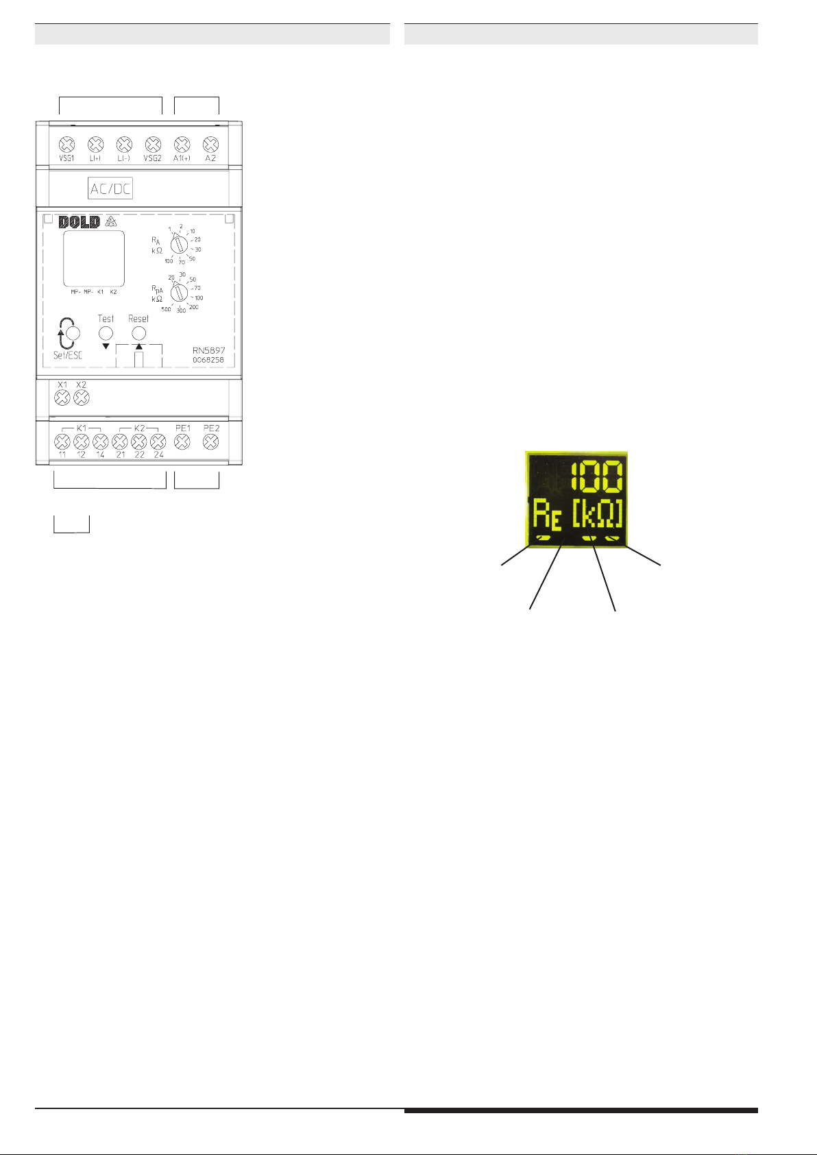
changing polarity is connected between L(+)/L(-) and PE1/PE2.The
momentary polarity of the measuring cycle is shown on the display by 2
curser segments („MP+“ for positive phase and „MP-“ for negative phase).
The duration of the positive and negative measuring phase depends on
the actual leakage capacity of the monitored system and in DC systems
also on the level and duration of possible voltage variations. This allows
a correct and fast measurement in different network conditions.
At the end of a measuring cycle the actual insulation resistance is produced
and indicated. The actual value is shown on the display. The relays for alarm
K1 and pre-alarm K2 switch when dropping under the adjusted response
values. In addition the backlight of the display changes to orange color
on pre-alarm or to red color on alarm. An asymmetric earth fault either to
„+“ or „-“ is also indicated on the display (only in DC- systems or with a
fault on the DC-side of a system).
Manual reset of fault message
Using the display menu in programming mode, the manual reset function
for insulation failures can be selected. If manual reset is activated the
insulation fault signals of the measuring circuit are stored when dropping
under the adjusted response values also if the insulation resistance goes
back to healthy state. The minimum value is stored and can be shown
on the display. Pressing the „Reset“ button on the front side for 2 s, the
alarm signal and the stored minimum value are reset if the actual insulation
resistance is in healthy state.
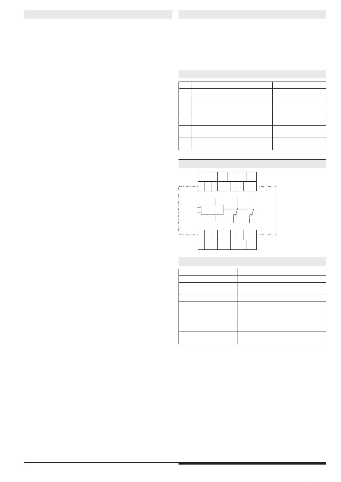
Indicator relay for insulation fault signal
For the indicator relays K1 (contacts 11-12-14, for alarm) and K2 (contacts
21-22-24, for pre-alarm) the function can be set in programming mode to
energized on trip or de-energized on trip when the insulation resistance
drops below the adjusted response value.
The status of the indicator relays is shown on the display with the two cursor
segments "K1" and "K2". When the relay is energized, the corresponding
curser lights up.
Disable the measuring function
Using the external control input X1/X2 the measuring function of the
RN 5897/020 can be disabled. This could be used when several isolated
voltage systems with individual insulation monitors need to be coupled.
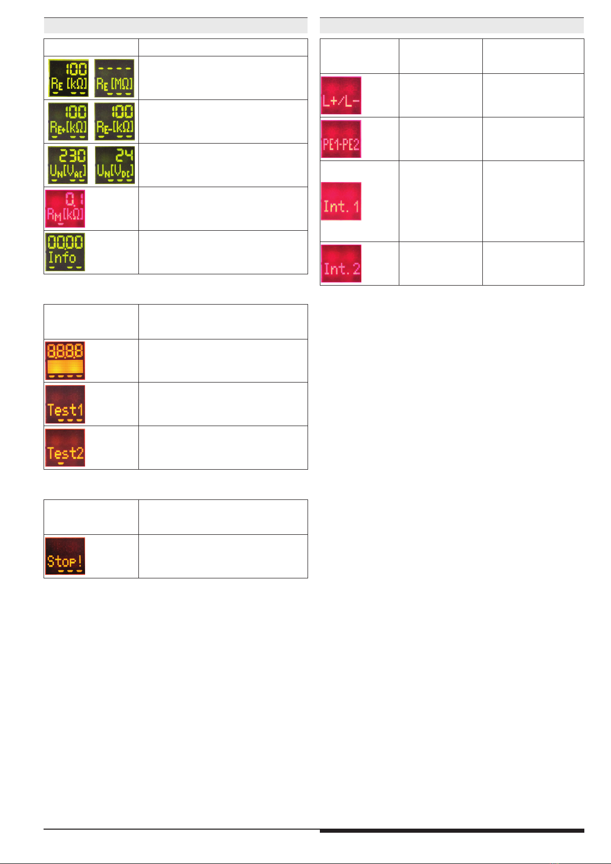
The measuring voltage is set to -90V (negative measuring phase) and the
evaluation of the measurement is stopped. The status of the output relays
is frozen and not changed any more. If the measurement is disabled the
colour of the display changes to orange and the text "Stop!" is displayed.
Please be aware, only the evaluation of the measurement is stopped and
the measuring pulse is interrupted! A high resistive disconnection to PE
does not take place (see internal resistance).
Broken wire detection
As described in section "Measuring circut", the measuring circuits L(+)/L(-)
and the protective conductors PE1/PE2 are constantly monitored for wire
breaks – not only at Power-On or a manual or occasional automatic test.
The response time of monitoring is only a few seconds. Broken wire
detection between L(+) and L(-) is performed via coupled alternating
voltage. This alternating voltage is short-circuited if the terminals are
connected to the connected mains at low-resistance. The device detects
that the mains to be monitored is properly connected.
Since this broken wire detection is carried out with alternating voltage, large
capacitances should be avoided between L(+) and L(-), since the capacitive
reactance of these capacitances also short-circuits this alternating voltage.
The device would no longer detect a connection fault on L(+)/L(-).
Especially parallel lines should be prevented over larger distances.
If larger capacitances between L(+)/L(-) cannot be avoided or if the coupled
alternating voltage interferes with the system, the broken wire detection can
be de-activated using the display menu in programming mode. Monitoring
deactivated, monitoring only during device test or continuous monitoring
(every 2 minutes for 10 s) are the possible options. If the broken wire
detection on L(+)/L(-) is de-activated no AC voltage is injected.
The broken wire detection on PE1/PE2 cannot be de-activated.
Device test functions
Principally, 2 different test functions are implemented: The "self-test" and
the "expanded test":
The self-test of the device is performed automatically after Power-On and
every full operating hours. It can also be triggered manually at any time by
pressing the "Test" button at the device front for 2 s.
With the self-test, contrary to the expanded test, the status of the Indicator
relays is not affected; the sequence is as follows:
The display backlight colour changes into orange. For approx.. 2 s all pixels
and segments of the LCD are shown. After that the text “Test1” comes up
and the measuring pulse is switched for approx. 5 s to negative test phase.
The polarity of the test voltage is also indicated on the display by curser
segments. Within these 5 s the internal measuring circuit is checked for
failures. Then the measuring pulse is switched for approx. 5 s to positive
test phase and more internal tests take place. If no failures turned up and
had been recognized, the measurement continuous. The extended test
procedure is started when during or at the end of the above described
12 s self-test the test button is pressed again for 2 s.
The sequence is similar to the self-test (2 measuring phases of 5 s each) but
in addition the output relays go in alarm stated. The display shows “Test2”.
The test phases of the extended test will be repeated continuously. The
extended test can be finished after the first complete sequence (approx.
10 sec) by pressing the "reset" button for 2 seconds. The device starts
the insulation monitoring again.
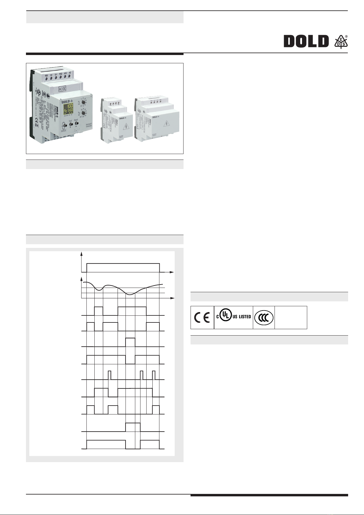
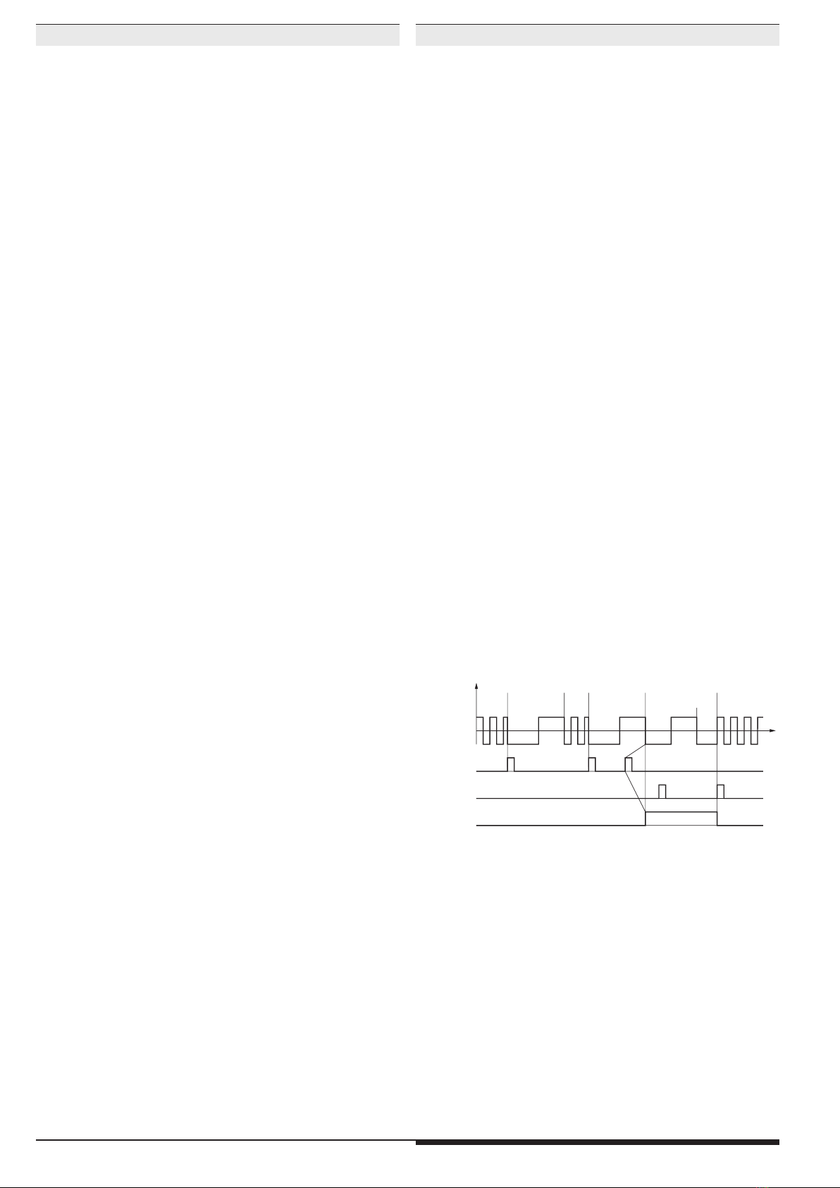
Test signal 1)
Reset signal 2)
Relay state K1 and K2
Measuring voltage
Positive
Alarm
No Alarm
Insulation
measurement Insulation
measurement
Insulation
measurement
3)
4)
Self test (Test 1)
Duration: approx. 12s
Self test (Test 1)
Duration: approx. 12s
Duration: approx. 10s
Continuous extended
test (Test 2)
Negative
M12462
U
t
1) Test signal: Button Test > 2 s oder X1/X2 > 1,5 s und < 10 s
2) Reset signal: Button Reset > 2 s oder X1/X2 < 1,5 s
3) To initiate the extended test (Test 2) the test signal must be operated
within the self test (Test 1) again..
4) The reset signal has here no function, as the first complete sequence
of extended test (Test 2) is not finished.
FunctionFunction

312.07.21 en / 423A
Behaviour with internal device faults
If internal device faults were detected during the test function, the display
backlight changes into red and an error messages (failure code: „Int.1“)
is indicated. The indicator relays K1 and K2 switch to the alarm state.
Behavior on faulty connection
When detecting broken wire on terminals L(+)/L(-), the measurement is
disabled. The reaction time could be up to 2 min. The monitoring relays
K1 and K2 go in alarm state, the backlight changes to red. The display
shows the fault message „L+/L-“. After removing the interruption the fault is
automatically reset (max. reaction time up to 2 min) and the measurement
of the insulation resistance is continued.
Stored alarm values remain stored. An interruption of the protective
earth connections PE1/PE2 causes the same reaction as interrupting the
measuring circuit, only the display shows „PE1-PE2“.
External control input
To terminals X1/X2 an external combined Test-/Reset button can be
connected. If the terminals X1/X2 are bridged for approx.
> 1,5 s and <
10 s
the test mode is started. This has the same function as pressing the
internal test button. When bridging X1/X2 for
< 1,5 s
, a stored alarm will
be reset. This has the same function as pressing the internal reset button.
If X1/X2 is activated for > 10 s, the measuring function is stopped.
The measuring function remains suspended for the duration of the control
of X1/X2.
Connection of an external coupling device
An external coupling device RL 5898 oder RP 5898 can be connected to
extend the input voltage range of the monitored voltage system on RN
5897/
020
. The terminals with the same legend of the insulation monitor
and the coupling device (VSG1, VSG2, L(+), L(-)) are connected together.
The network to be monitored is connected to terminals L1(+) und L2(-) on
the coupling device. Using the display menu in programming mode the
connection of the coupling device has to be selected and activated. The
broken wire detection is active on the terminals L1(+)/L2(-) on the coupling
device. A broken wire between coupling device and insulation monitor
cannot be detected immediately but the measured values on interruption
of 1 or 2 wires between coupling device and insulation monitor are much
lower as the real values, which will cause an early response of the device.
Programming/setting of parameters/set-up of the insulation monitor
The response values for alarm and pre-alarm can be adjusted via 2 rotary
switches „R
A
“ and „R
pA
“ on the front of the device. New setting are immediately
active and do not require a restart of the unit. More settings can be done
with the 3 buttons and the display menu in programming mode. To start the
programming mode, the button „Set/ESC“ has to be pressed for approx.
2 s. To avoid unauthorized manipulation, this button as well as the rotary
switches„R
A
“ and „R
pA
“ are located behind a sealable transparent cover. When
the device changes to programming mode, the measurement is stopped,
the display back light changes to orange color and the first parameter is
displayed. To scroll the different parameters, the button „Set/ESC“ has to
be pressed short. With the 2 scroll buttons (Scroll-Up „
“ and Scroll-Down
„
“) the settings can be modified.
The first parameter is the broken wire detection in the measuring circuit
„BrWiD“. Possible setting are continuously on („on“), continuously off („oFF“)
or only active during self-test. The default is „on“.
The second parameter is alarm memory „Mem.“. Here are 2 options available
manual reset („on“) und auto reset („oFF“). The default value is „oFF“.
The third parameter is the relay operation principle „Rel.“ Settings are:
de-energized on trip („n.c.“) and energized on trip („n.o.“). The default
value is „n.c.“.
The fourth parameter is the type of network connection „Net“. Selection
are AC Network(„Ac“),DC-Network („dc“) or 3NAC-Network („3nAc“). The
default value is „Ac“.
The device allow the connection of a coupling device, the fifth parameter
activates („on“) or de-activates („oFF“) the coupling device.
The leave the programming mode the button „Set/ESC“ has to be pressed
for 2 s. The settings will be activated and stored permanently. After that the
device makes a restart similar to power on.
Function Function
Connection Terminals
Terminal designation Signal description
A1(+), A2 Auxiliary voltage AC or DC
L(+), L(-), VSG1, VSG2 Connection for measuring ciruit or
Connection for coupling device
PE1, PE2 Connection for protective conductor
X1, X2
Control input
(combined external Test- and Reset-input
with additional Stop of the measuring
function)
11, 12, 13 Alarm signal relay K1(1 changeover contact)
21, 22, 23 Prewarning signal relay K2 (1 changeover
contact)
Circuit Diagram
Default-Setting of Parameters
Nr. Parameter Default-Set
1
Broken wire detect in measuring circuit
“Broken Wire Detect” on
2
Storing insulation fault message
“Memory” off
3
Switching mode of output relays
“Relay”
n.c. (normally closed)
de-energized on trip
4
Power supply type
“Net” AC
5Ext.
coupling device
“VSG” off
X1 X2
11 12 14 21 22 24 PE1 PE2
A2
A1(+)
L(+)VSG1 VSG2
L(-)
22
12
L(+) L(-)
24
14
21
PE2
11
PE1
UH
M11956_a

412.07.21 en / 423A
Indicators Indicators
The colour of the backlight indicates the operating status of the device.
Off: No auxiliary voltage connected
Green: Normal operation (Insulation resistance in healthy state)
Red: Alarm (measured value below alarm response value,
device failure, connection failure)
Orange: Warning (measured value below pre-alarm response value,
test mode, Parameter set-up mode)
Actual value display
The actual insulation resistance „RE[kΩ]“ is displayed.If the actual value is RE
<
10 kΩ, the value in kΩis displayed with 1 decimal place.With values 10 kΩ≤RE
< 500 kΩthe display shows the value without decimal place, with values 500
kΩ≤RE
< 1 MΩthe value is rounded to 10 kΩ. Insulation resistance values 1
MΩ≤RE
<2 MΩaredisplayedinMΩwithonedecimal place.If the resistance is
RE> 2 MΩthe display indicates ---- showing the value is higher the 2 MΩ.
In a DC Network an asymmetric insulation resistance to „+“ or „-“ is indi-
cated by displaying „RE+[kΩ]“ or „RE-[kΩ]“
By pressing the scroll buttons (Scroll-Up „“ und Scroll-Down „“) more
measured values can be shown. Another value is the mains voltage on
L(+)/L(-).This is indicated with „UN[VAC]“ or „UN[VDC]“ in V depending on
the type of network and voltage. If the unit is connected single pole to a
3NAC network the mains voltage cannot be measured. With this setting
the voltage value is not displayed. When manual reset is selected, the
display shows the minimum stored value of the resistance „RM[MΩ]“ or
„RM[kΩ]“ after the value dropped below the response value also when the
value goes back to healthy state. The stored minimum value will only be
reset when acknowledging the stored Alarm signal (with the reset button).
Also the firmware version can be displayed.
Positive measurement
phase active (MP+)
Negative measurement
phase active (MP-)
Pre-Alarm monitoring
relay K2 energized
Alarm monitoring relay
K1 energized
RN 5897/020
Connection
measuring ciruit
or
Coupling device Auxiliary
voltage
M11958_a
Indicator relay
alarm and pre-alarm
Protective
conductor
External
control input

512.07.21 en / 423A
Indicators
Display-Indication Measuring- resp. display value
Insulating resistance in kΩresp. MΩ
(„----“ complies RE ≥2 MΩ)
Asymmetrical insulating resistance in kΩ
against L+ or L- at DC-mains
Measured mains voltage in V
at AC- or DC-mains
(„----“ indicates invalid voltage value or
voltage < 5 V)
Stored min. insulating resistance
in kΩresp. MΩ
Latest firmware-version
Display-Indication Test function
Display-Test
Selftesting
(measuring switching, measuring voltage,
internal tests)
Advanced Test
(additional control of indicator relay)
Display-Indication Function
Measuring function stopped
Error Indication
Display-Indication Failure cause Failure recovery
Broken wire detection
on L(+)/L(-).
Check
measuring circuit
L(+) and L (-)
Broken wire detection
on PE1/PE2.
Check
protective conductor
connections
PE1 and PE2
Internal failure
detected in
test mode
Press test button again
or restart the unit by
interrupting the auxiliary
supply temporarily.
If the fault remains
permanent, send device
back to manufacturer for
examination.
Faulty calibration
values detected in
device memory.
Send device back
to manufacturer for
recalobration and
examination.

612.07.21 en / 423A
Notes
WARNING
Risk of electrocution!
Danger to life or risk of serious injuries.
• Disconnect the system and device from the power supply and ensure
they remain disconnected during electrical installation.
• The display of the voltage is not in real time. The Value on the display is
updated at the end of a measuring cycle.
• Determine voltage free status by using appropriate instruments
• The terminals of the control input X1-X2 have no galvanic separation to
the measuring circuit L(+) and L(-) and are electrically connected together,
therefore they have to be controlled by volt free contacts or bridge. These
contacts ore bridges must provide a sufficient separation depending on
the mains voltage on L(+)-L(-).
• Please do not connect external voltage to terminals X1/X2. The control
must only be made by bridging X1 and X2.
• The coupling unit
RL 5898 or RP 5898
must only be used in conjunction
with the RP5897/020 on a voltage system and not just by itself.
!
Attention!
• Before checking insulation and voltage, disconnect the monitoring device
RN 5897/020 from the power source!
• In one voltage system only one insulation monitor can be used.This has
to be observed when interconnecting two separate systems..
• Device terminals PE1 and PE2 must always be connected via separate
lines to different terminal points of the protective-conductor system.
• The device must not be operated without PE1/PE2 connection!
nfo
Attention!
• The main measuring circuit can be connected with its terminals L(+) and
L(-) both to the DC and also AC side of a mixed network; it is done most
practically where the primary incoming power supply takes place e.g.
with battery networks with connected inverters on the DC side, with
Generators/Transformers with connected Rectifiers or inverters on the
AC-side. To monitor a 3NAC system the device can be connected single
pole, (L(+) and L(-) are bridged, to the neutral of the 3p4w system. The 3
phases have a low-Ωic (approx. 3 – 5 Ω) connection via the transformer
windings so also insulation failures of the not directly connected phases
are detected. Via the display menu in programming mode the correct
type of network needs to be selected (see „Connection Examples“).
• If a monitored AC system includes galvanically connected DC circuits
(e.g. via a rectifier), an insulation failure on the DC side can only be
detected correctly, when a current of min 10 mA can flow via the semi-
conductor connections.
• If a monitored DC system includes galvanically connected AC circuits
(e.g. via an inverter), an insulation failure on the AC side can only be
detected correctly, when a current of min 10 mA can flow via the semi-
conductor connections.

712.07.21 en / 423A
Running chart
Press button
Scroll Up „▲“
Press button
Scroll Down „ ▼“
Press button
„Set/ESC“ >2s
Set parameters
Parameter 1:
Broken wire detect in
measuring circuit
„BrWiD“
(Broken Wire Detect)
Default: „on“
Parameter 2:
Storing insulation fault
message
„Mem.“
(Memory)
Default:
„
oFF“
Parameter 3:
Switching mode of
output relays
„Rel.“
(Relay)
Default:
„
n.c.“
Parameter 4:
Power supply type
„Net“
Default: „Ac“
Parameter 5:
Ext. coupling device
„VSG“
Default: „oFF“
Parameter 1:
Broken wire detect in
measuring circuit
„BrWiD“
(Broken Wire Detect)
„oFF“
Parameter 1:
Broken wire detect in
measuring circuit
„BrWiD“
(Broken Wire Detect)
„tESt“
Parameter 2:
Storing insulation fault
message
„Mem.“
(Memory)
„
on“
Parameter 3:
Switching mode of
output relays
„Rel.“
(Relay)
„
n.o.“
Parameter 4:
Power supply type
„Net“
„dc“
Parameter 4:
Power supply type
„Net“
„3nAc“
Parameter 5:
Ext. coupling device
„VSG“
„on“
Press button
„Set/ESC“
Press button
„Set/ESC“ >2s
End of programming

812.07.21 en / 423A
Nominal consumption:
DC 12 V, 24 V, 48 V: Max. 3 W
AC 230 V: Max. 3.5 VA
Control input X1/X2 for external kombinierte Test-/Reset-Taste
Current flow: Approx. 3 mA
No-load operation voltage
X1 to X2: Approx. 12 V
Permissible wire length: < 50 m
Activat. time t for test signal: 1.5 s < t < 10 s
Activat. time t for reset signal: t < 1.5 s
Activation time t for Stop
of the measuring function: t > 10 s
Outputs
Indicator contact: 2 x 1 changeover contact for Alarm (K1)
and Pre-Alarm (K2)
energized or de-energized on trip
(programmable)
Thermal current Ith:4 A
Switching capacity
To AC 15:
NO contact: 5 A / AC 230 V IEC/EN 60947-5-1
NC contact: 2 A / AC 230 V IEC/EN 60947-5-1
To DC 13: 2 A / DC 24 V IEC/EN 60947-5-1
Electrical life
At 5 A, AC 230 V: 1 x 10⁵switching cycles
Short circuit strength
max. fuse rating: 4 A gG / gL IEC/EN 60947-5-1
Mechanical life: 50 x 106switching cycles
General Data
Operating mode: Continuous operation
Temperature range
Operation: - 30 ... + 60 °C
(at range 0 … -30 °C limited
function of the LCD display)
Storage: - 30 ... + 70 °C
Altitude: ≤2000 m IEC 60664-1
Clearance and creepage
distances
Rated insulation voltage: 300 V
Overvoltage category: III
Rated impuls voltage /
pollution degree: IEC 60664-1
Measuring circuit L(+)/L(-) to
auxiliary voltage A1(+)/A2 and
indicator relay contacts K1, K2: 4 kV / 2
Auxiliary voltage A1(+)/A2 to
indicator relay contacts K1, K2: 4 kV / 2
Indicator relay contact K1 to
indicator relay contacts K2: 4 kV / 2
Insulation test voltage
Routine test: AC 2.5 kV; 1 s
EMC
Electrostatic discharge (ESD): 8 kV (air) IEC/EN 61000-4-2
HF irradiation:
80 MHz … 1 GHz: 20 V / m IEC/EN 61000-4-3
1 GHz … 2.7 GHz: 10 V / m IEC/EN 61000-4-3
Fast transients: 2 kV IEC/EN 61000-4-4
Surge voltage
Between
wires for power supply: 1 kV IEC/EN 61000-4-5
Between wire and ground: 2 kV IEC/EN 61000-4-5
HF-wire guided: 20 V IEC/EN 61000-4-6
Interference suppression: Limit value classe B EN 55011
Degree of protection
Housing: IP 40 IEC/EN 60529
Terminals: IP 20 IEC/EN 60529
Housing: Thermpolastic with V0 behaviour
according to UL subject 94
Vibration resistance: Amplitude 0.35 mm,
Frequency 10 ... 55 Hz, IEC/EN 60068-2-6
frequency 2 ... 13.2 Hz, 13.2 ... 100 Hz,
acceleration ±0.7 gn IEC/EN 60068-2-6
Shock resistance: 10 gn / 11 ms, 3 pulses IEC/EN 60068-2-27
Climate resistance: 30 / 060 / 04 IEC/EN 60068-1
Terminal designation: EN 50005
Measuring ciruit L(+)/L(-) to PE1/PE2 (without coupling device)
Nominal voltage UN: AC / DC 0 ... 230 V
Max. voltage range UN: AC 0 ... 250 V
DC 0 ... 300 V
Frequency range: DC or 40 ... 1000 Hz
Max. line capacitance: 5 µF
Internal resistance (AC / DC): > 90 kΩ
Measuring voltage: Approx. ±90 V
Max. mesured current (RE= 0): < 1.10 mA
Response inaccuracy: ±15 % ±1.5 kΩ IEC 61557-8
Response value hysteresis: Approx. + 25 %; min. + 1 kΩ
On delay
At CE= 1µF,
response value ≤100 kΩ,
REof ∞to 0.5 * response value: ≤1 s
At CE= 1µF,
response value > 100 kΩ,
REof ∞to 0.5 * response value: < 2 s
Measuring time:
At CE= 1 … 5 µF < 5 s
Min. operate time: > 0.2 s
Response values
Pre-warning („RpA“):
kΩ: 20 30 50 70 100 200 300 500
Alarm („RA“)
kΩ: 1 2 10 20 30 50 70 100
Each adjustable via rotational switches
Response value broken
wire detection L(+)/L(-): > Approx. 90 kΩ
Response value broken
wire detection PE1/PE2: > Approx. 0.5 kΩ
Meas. ciruit L1(+)/L2(-) to PE1/PE2 (with coupling device RL / RP 5898)
RL 5898 RP 5898
Nominal voltage UN:AC 0 ... 400 V AC 0 ... 690 V
DC 0 ... 500 V DC 0 ... 1000 V
Max. max. voltage range UN:AC 0 ... 440 V AC 0 ... 760 V
DC 0 ... 550 V DC 0 ... 1100 V
Frequency range: DC or 40 ... 1000 Hz
Max. line capacitance: 5 µF
Internal resistance (AC / DC): > 240 kΩ
Measuring voltage: Approx. ±90 V
Max. mesured current (RE= 0): < 0.40 mA
Response inaccuracy: ±15 % ±1.5 kΩ IEC 61557-8
Response value hysteresis: Approx. + 25 %; min. + 1 kΩ
On delay
At CE= 1µF,
response value ≤100 kΩ,
REof ∞to 0.5 * response value: ≤1 s
At CE= 1µF,
response value > 100 kΩ,
REof ∞to 0.5 * response value: < 2 s
Measuring time:
At CE= 1 … 5 µF < 5 s
Min. operate time: > 0.2 s
Response values
Pre-warning („RpA“):
kΩ: 20 30 50 70 100 200 300 500
Alarm („RA“)
kΩ: 1 2 10 20 30 50 70 100
Each adjustable via rotational switches
Response value broken
wire detection L1(+)/L2(-): > Approx. 500 kΩ
Response value broken
wire detection PE1/PE2: > Approx. 0.5 kΩ
Max. wire length
between insulation monitor
and coupling device: < 0.5 m
Auxiliary voltage input A1(+)/A2
Nom. Voltage Voltage range Frequency range
AC/DC 24 ... 60 V AC 19 ... 68 V 45 … 400 Hz; DC 48 % W*)
DC 16 ... 96 V W*)≤5 %
AC/DC 85 ... 230 V AC 68 ... 276 V 45 … 400 Hz; DC 48 % W*)
DC 67 ... 300 V W*)≤5 %
DC 12 ... 24 V DC 9.6 ... 30 V W*)≤5 %
*)W = Permitted residual ripple of auxiliary supply
Technical Data Technical Data

912.07.21 en / 423A
Wire connection DIN 46228-1/-2/-3/-4
Cross section: 0.5 ... 4 mm² (AWG 20 - 10) solid or
0.5 ... 4 mm² (AWG 20 - 10)
stranded wire without ferrules
0.5 ... 2.5 mm² (AWG 20 - 10)
stranded wire with ferrules
Stripping length: 6.5 mm
Wire fixing: Cross-head screw / M3 box terminals
Fixing torque: 0.5 Nm
Mounting: DIN rail IEC/EN 60715
Weight: Approx. 205 g
Dimensions
Width x height x depth: 52.2 x 90 x 71 mm
Technical Data Standard Types
RN 5897.12/020/61 DC 12 ... 24 V
Article number: 0068260
• Auxiliary voltage: DC 12 ... 24 V
RN 5897.12/020/61 AC/DC 24 … 60 V
Article number: 0068258
• Auxiliary voltage: AC/DC 24 … 60 V
RN 5897.12/020/61 AC/DC 85 … 230 V
Article number: 0068259
• Auxiliary voltage: AC/DC 85 … 230 V
• Outputs: 1 changeover contact for pre-warning
1 changeover contact for alarm
• Setting range pre-warning: 20 kΩ… 500 kΩ
• Setting range alarm: 1 kΩ… 100 kΩ
• With connection facility of a coupling device RL 5898 or RP 5898
• Max. line capacitance: 5 µF
• Energized or de-energized on trip
• Selection of type of network
• Width: 52.5 mm
Ordering Example for variants
RN 5897 .12
/020 /61 AC/DC 24 … 60 V 1 kΩ- 100 kΩ20 kΩ- 500 MΩ
Setting range Pre-warning
Setting range alarm
Auxiliary voltage
UL approval
Variant, if required
Contacts
Type
Meas. ciruit L1(+)/L2(-) to PE1/PE2 (with coupling device RL / RP 5898)
RL 5898 RP 5898
Max. voltage range UN:AC 0 ... 400 V AC 0 ... 600 V
DC 0 ... 500 V DC 0 ... 600 V
Output voltage at
L(+)/L(-), VSG1/VSG2: Max. AC / DC 230 V
Switching capacity: Pilot duty C300, R300
5A 250Vac
2A 30Vdc
Wire connection: 60 °C / 75 °C copper conductors only
Torque 0.5 Nm
Test specification: ANSI/UL 60947-1, 5th Edition
ANSI/UL 60947-5-1, 3rd Edition
CAN/CSA-C22.2 No. 60947-1-13,
2nd Edition
CAN/CSA-C22.2 No. 60947-5-1-14,
1st Edition
nfo
Technical data that is not stated in the UL-Data, can be found
in the technical data section.
UL-Data
Accessories
RL 5898/61
Article number: 0068315
• Coupling device for RN 5897.12/020
• Extension of nominal voltage range UN
to DC 500 V, AC 400 V
• Weight: Approx. 60 g
• Dimensions
- Width x height x depth: 35 x 90 x 71 mm
Insulation monitor
connection
Measuring ciruit
M12054_a
Vibration and
shock resistance: Category 1, Class B IEC/EN 61373
Ambient temperature: OT1 compliant
Protective coating of the PCB: No
Classification to DIN EN 50155
Switching capacity
To AC 15
NO contact: 3 A / AC 230 V
NC contact: 1 A / AC 230 V
nfo
Technical data that is not stated in the CCC-Data,can be found
in the technical data section.
CCC-Data
RN 5897.12/020: With modified alarm value range
Alarm ("RA"):
kΩ: 10, 20, 30, 50, 100, 200, 300, 500
Article number: 0069226
Variants

10 12.07.21 en / 423A
Connection Example
*1) Auxiliary voltage UH(A1(+)/A2) ) can also be sourced from the
monitored voltage system.
The voltage range of the auxiliary supply has to be taken into
account.
*2) Control input X1/X2 for external combined Test-/Reset-button with
Stop of the measuring function:
• Control 1.5 s < t < 10 s: Test function
• Control < 1.5 s: Reset function
• Control > 10 s: Stop of measuring function
VSG1
VSG1
L(+)
L(+)
L(-)
L(-)
PE
RN5897/020
X1
External combined
test/reset button
VSG2
VSG2
X2 11PE1 12PE2 14 21 22 24
M11961_a
*2)
A1(+) A2
UH
*1)
L1
L2
L3 UN
L1(+) L2(-) Setting of type of network:
AC
External coupling device:
ON
RL5898
RP5898
Ungrounded mains
RL5898: 3 AC 0...440V 40...1000Hz
RP5898: 3 AC 0...760V 40...1000Hz
L1
Ungrounded mains
3N AC 400V/230V 40...1000Hz
L2
L3
N
RN5897/020
X1
external combined
test/reset button
X2 11PE1 12PE2 14 21 22 24
M11964
*2)
A1(+) A2
UH
*1)
UN
PE
Setting of type of network
3N AC
:
L(+)VSG1 L(-) VSG2
Accessories
Flush mounting kit
Order reference: KU 4087-150/0056598
For universal use with:
·R-series devices of
17.5 to 105 mm width
·Easy mounting
Accessories
RP5898/61
Article number: 0066944
• Coupling device for RN 5897.12/020
• Extension of nominal voltage range UN
to DC 1000 V, AC 690 V
• Weight: Approx. 110 g
• Dimensions
- Width x height x depth: 70 x 90 x 71 mm
Insulation monitor
connection
Measuring ciruit
M11599_a

11 12.07.21 en / 423A
Connection Example
L1
Single phase mains, isolated from earth
AC 0...250V 40...1000Hz
L2
L(+)VSG1
RN5897/020
X1
External combined
test/reset button
L(-) VSG2
X2 11PE1 12PE2 14 21 22 24
M11967_a
*2)
A1(+) A2
UH
*1)
UN
Setting of type of network
AC
coupling device:
OFF
:
External
L1
L2
VSG1
VSG1
L1(+)
L(+)
L(+)
L(-)
L(-)
PE
RN5897/020
X1
External combined
test/reset button
VSG2
VSG2
L2(-)
X2 11PE1 12PE2 14 21 22 24
M11970_a
*2)
A1(+) A2
UH
*1)
UN
Setting of type of network:
DC
External coupling device:
ON
RL5898
RP5898
Single phase mains, isolated from earth
RL5898: AC 0...440V 40...1000Hz
RP5898: AC 0...760V 40...1000Hz
VSG1
VSG1
L(+)
L(+)
L(-)
L(-)
PE
RN5897/020
X1
External combined
test/reset button
VSG2
VSG2
X2 11PE1 12PE2 14 21 22 24
M11976_a
*2)
A1(+) A2
UH
*1)
L+
L-
UN
L1(+) L2(-) Setting of type of network:
DC
External coupling device:
ON
RL5898
RP5898
Ungrounded DC network
RL5898: DC 0...550V
RP5898: DC 0...1100V
L(+)VSG1
RN5897/020
X1
external combined
test/reset button
L(-) VSG2
X2 11PE1 12PE2 14 21 22 24
M11973
*2)
A1(+) A2
UH
*1)
PE
L+
Ungrounded DC network
DC 0...300V
L-
UN
Setting of type of network
DC
coupling device:
OFF
:
External
*1) Auxiliary voltage UH(A1(+)/A2) ) can also be sourced from the monitored voltage system.
The voltage range of the auxiliary supply has to be taken into account.
*2) Control input X1/X2 for external combined Test-/Reset-button with Stop of the measuring function:
• Control 1.5 s < t < 10 s: Test function
• Control < 1.5 s: Reset function
• Control > 10 s: Stop of measuring function

12 12.07.21 en / 423A
E. Dold & Söhne GmbH & Co. KG • D-78120 Furtwangen
dold-relays
@dold.com • www.dold.com
• Bregstraße 18 • Phone +49 7723 654-0 • Fax +49 7723 654356
Other manuals for VARIMETER IMD RN 5897/020
1
This manual suits for next models
2
Table of contents
Other DOLD Monitor manuals