Dormakaba 1460 User manual

EN
User Manual
dormakaba Programmer
1460
- 06/2021

Contents User Manual
2 - 06/2021dormakaba Programmer 1460
Contents
1 Regarding this document 4
1.1 Validity 4
1.2 Target group 4
1.3 Contents and purpose 4
1.4 Document availability 4
1.5 Supplementary documentation 4
1.6 Abbreviations/definition of terms 5
1.7 Warnings 6
2 Basic safety instructions 7
2.1 Designated use 7
2.2 Safety information 7
2.3 Service and maintenance 7
2.4 ESD prevention measures 8
3 Product description 9
3.1 Overview 9
3.1.1 Layout 9
3.1.2 Display symbols 10
3.2 Scope of delivery 10
3.3 Technical details 11
3.4 Conformity 11
4 Operation 12
4.1 Control elements 12
4.1.1 ON/OFF button 12
4.1.2 Menu buttons 12
4.1.3 Navigation buttons and ENTER 12
4.1.4 Alphanumeric buttons 13
4.1.5 Home button 13
4.2 Switching on the programmer 13
4.3 Display dialogues 13
4.4 Wireless programming 14
4.5 Settings 14
4.5.1 Programmer settings 14
4.5.2 Actuator settings 19
4.5.3 Data settings 25
5 Programming 27
5.1 Setting the properties and functions of a component 27
5.2 System level 27
5.3 Export to components 29
5.3.1 Export to evolo components 29
5.3.2 Updating evolo components 29
5.3.3 Export to mechatronics cylinders 30
5.3.4 Updating a mechatronics cylinder 30
5.4 Import from components 31
5.4.1 Info 31
5.4.2 Read traceback 32
5.4.3 Diagnostic details 32
5.4.4 Import from digital cylinder, c-lever and reader 33
5.4.5 Import from mechatronics cylinder 33
5.4.6 Info for TouchGo components (signal strength) 34
5.4.7 Configuration 35
5.5 Manual settings 35

ContentsUser Manual
3- 06/2021 dormakaba Programmer 1460
5.6 Firmware update of components 35
5.6.1 Firmware update of V4 actuators 35
5.6.2 Crossgrade for LEGIC advant components 36
6 System connection 40
6.1 Driver installation 40
6.2 Downloading data from the system software 41
6.3 Set clock 41
7 Maintenance 42
7.1 Battery charge status 42
7.2 Charging the battery 42
7.3 Menu structure 43
8 Service 44
8.1 EAC Service Tool 44
8.1.1 Programmer 1364 – updating firmware 45
8.1.2 Programmer 1460 – updating firmware 45
8.1.3 Actuators – updating firmware 45
8.1.4 Updating desktop reader 91 08 46
8.1.5 Creating a programmer memory image 47
8.2 Emergency supply 47
9 Error messages/troubleshooting 49
10 Disposal 50

1 Regarding this document
This section contains information about properly using this document.
1.1 Validity
This document describes the product:
Product designation: Programmer 1460
Types: 1460
Firmware version: from 01.34 onwards
Article number: 1460
1.2 Target group
This manual is intended for skilled persons only.
The descriptions are intended for skilled persons trained by the manufacturer. This manual is
not a replacement for product training.
For reasons of equipment safety, the installation, maintenance and service measures
described in this documentation should only be carried out by skilled persons in accordance
with EN 62368-1 (Audio/Video, Information and Communication Technology Equipment –
Part 1: Safety Requirements).
Skilled person is the designation for people who have the appropriate technical training and
experience in setting up the equipment. Skilled persons are expected to use their training and
experience to identify any risks to themselves and others that may arise while carrying out
these activities, and to minimise these risks as far as possible. It is the skilled person’s
responsibility to ensure that the conditions stated by the manufacturer and the applicable
regulations and standards are complied with when carrying out these actions.
This documentation is also used to provide information for persons with the following tasks:
• Project planning and project implementation
• Connecting the product to user software by programming customer applications
• Customer-specific adjustments with product parameterisation
1.3 Contents and purpose
The contents of the guide are limited to operation, putting into operation, programming, data
transmission and servicing of the product.
1.4 Document availability
Additional documentation is available on the dormakaba website. The manuals can be found
in a protected area (extranet). They can be accessed using the user account of trained
specialists or a temporary user account.
https://www.dormakaba.com/extranet-emea-en/login
1.5 Supplementary documentation
• evolo system description
• PG wireless gateway 9040 planning guideline
• System software documentation, e.g. KEM
Regarding this document User Manual
4 - 06/2021dormakaba Programmer 1460
1.6 Abbreviations/definition of terms
To make this document easier to read, the following short designations are used for the
product designations, as well as the following symbols:
Short name Product designation/definition
evolo dormakaba evolo
Reader dormakaba remote reader
dormakaba compact reader
Digital cylinder dormakaba digital cylinder
Mechatronic cylinder dormakabamechatronic cylinder, surface-fixed
dormakabamechatronic cylinder, compact
dormakabamechatronic cylinder, forend
Terminal dormakaba terminal 94 20
TouchGo dormakaba c-lever TouchGo
c-lever dormakaba c-lever
dormakaba c-lever compact
dormakaba c-lever pro
dormakaba c-lever air
Cabinet lock dormakaba cabinet Lock 21 10
Wireless Reader dormakaba remote reader 9115 (E320) with wireless extension
module 9043
Desktop reader dormakaba desktop reader 9108
Programmer 1364 dormakaba Programmer 1364
Programmer 1460 dormakaba Programmer 1460
KEM dormakaba evolo Manager
EST dormakaba EAC Service Tool
UID Unique number
MRD Multi RFID device
AoC Access on Card
OSS-SO OSS Standard Offline
NFC Near Field Communication
Bluetooth Bluetooth®
BLE On the PD display: Bluetooth Low Energy
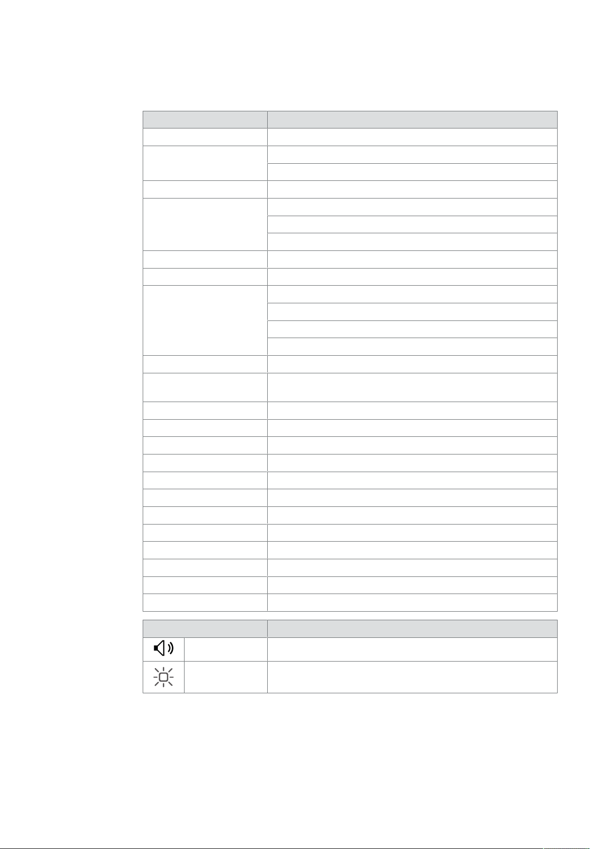
Symbols Acoustic signal
Visual signal
There is no visual signalling for components without a visual display option.
Regarding this documentUser Manual
5- 06/2021 dormakaba Programmer 1460
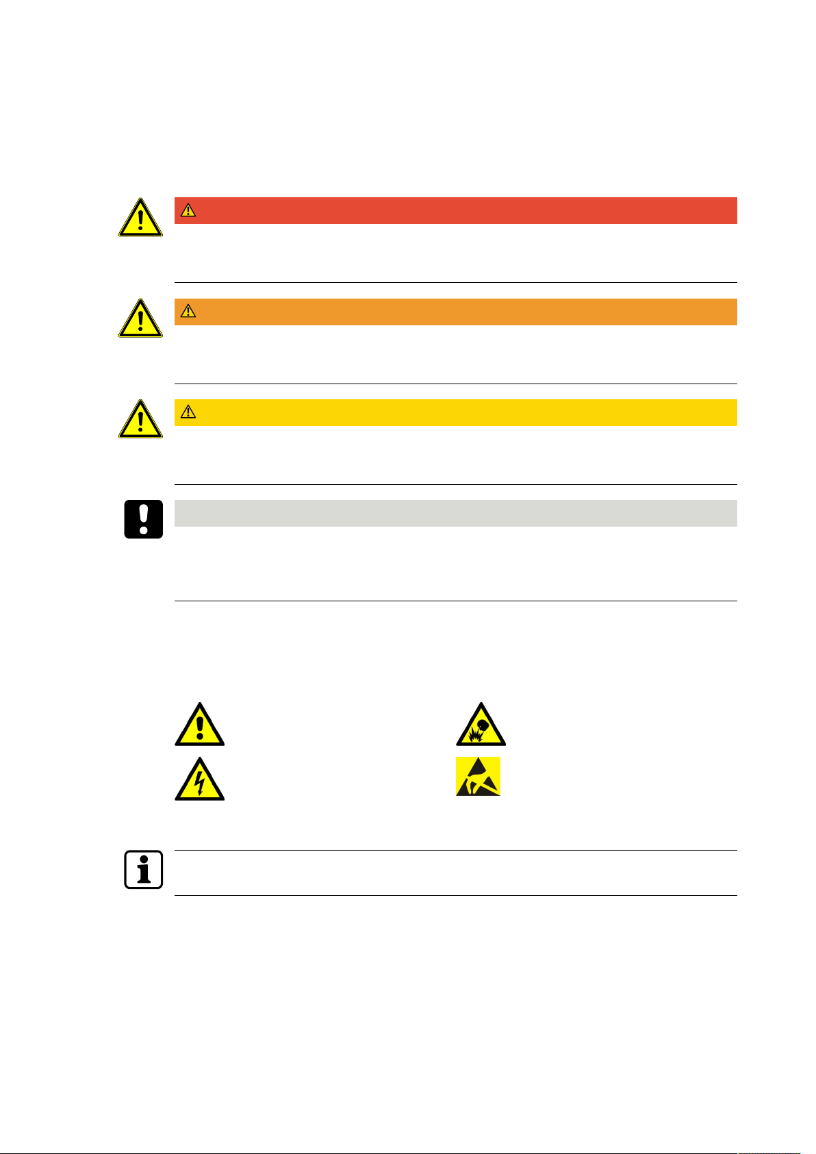
1.7 Warnings
This manual contains information that you must observe for your own personal safety and to
avoid material damage. The information regarding your personal safety is highlighted via a
warning triangle; information regarding isolated material damage does not have a warning
triangle. Depending on the hazard level, the warning information is displayed in decreasing
order as follows:
DANGER
High risk
Indicates an imminent danger which could cause severe physical injury or death.
WARNING
Medium risk
Indicates a possibly dangerous situation which may lead to severe physical injury or death.
CAUTION
Low risk
Indicates a possibly dangerous situation which may lead to minor physical injury.
NOTICE
Important information on the correct use of the product.
Failure to comply with these instructions could lead to malfunctions. It is possible to damage
the product.
The warning information for the highest level in each case is always used when several hazard
levels occur at the same time. If warning information warns about personal injury, the same
piece of warning information may also warn about material damage.
Other warning symbols:
General hazard Risk of explosion
Danger from electric voltage ESD: Danger from electrostatic dis-
charge
Useful tips and information regarding safe operation of the product are labelled as follows:
Tips for usage, useful information.
These help to make the best use of the product and its functions.
Regarding this document User Manual
6 - 06/2021dormakaba Programmer 1460

2 Basic safety instructions
This product has been built to state-of-the-art standards and in line with established safety
regulations. However, hazards for persons and property may arise when handling the product.
Read and observe the following safety instructions before using the product.
2.1 Designated use
This product is intended for use as specified and explained in the Product description section
only. Any other use is considered non-designated use. The manufacturer is not liable for any
damage or injury due to non-designated use. The user/facility operator is the sole person to
bear risks for non-designated use.
2.2 Safety information
The following safety instructions must be followed for safe use of the device.
CAUTION
The electronic device must be protected from the following external influences:
direct sunlight
direct heat sources (such as heating)
direct fluids (such as water)
temperature fluctuations (e.g. below 0°C).
2.3 Service and maintenance
Conversions and modifications to the product may only be done skilled personnel (see chapter
1 Target group). Any conversions and modifications performed by other persons will exempt
us from any liability.
Opening the device will lead to exclusion of all liability and warranty.
This excludes replacing the batteries.
The elimination of faults and maintenance work may only be performed by skilled personnel
(see chapter 1 Target group).
Basic safety instructionsUser Manual
7- 06/2021 dormakaba Programmer 1460
2.4 ESD prevention measures
NOTICE
Risk for electronic components due to electrostatic discharge.
Incorrect handling of electronic PCBs or components can result in damage which will cause a
complete breakdown or sporadic errors.
• General ESD prevention measures must be observed when installing or repairing the
product.
• Wear an anti-static wrist strap when handling electronic components. Connect the end of
the strap to a discharge box or a non-painted, earthed metal component. This way, static
discharges are channelled away from your body safely and effectively.
• Handle a PCB along its edges only. Do not touch the PCB or connectors.
• Place dismantled components on an anti-static surface or in an anti-static shielded con-
tainer.
• Avoid contact between PCBs and clothing. The wrist strap protects PCBs against an elec-
trostatic discharge voltage from the body only. However, damage can also be caused by
an electrostatic discharge voltage from clothing.
• Transport and ship dismantled modules in conductive anti-static bags only.
Basic safety instructions User Manual
8 - 06/2021dormakaba Programmer 1460
3 Product description
This section provides an overview of the product and gives information on technical details.
3.1 Overview
The programmer enables standalone components to be programmed and configured by
specialists. At the same time, the programmer is the link (interface) between the system
software and the components.
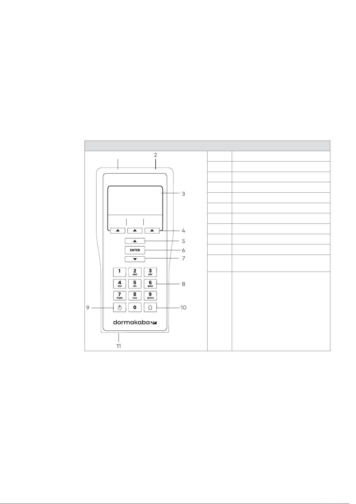
3.1.1 Layout
Programmer 1460
1
1 Radio interface
2 Programming cable connector
3 Display
4 Menu buttons
5 UP, navigation button
6 ENTER
7 DOWN, navigation button
8 Alphanumeric buttons
9 ON/OFF button
10 Home, Cancel, Back
11 USB interface/main charger con-
nector
Product descriptionUser Manual
9- 06/2021 dormakaba Programmer 1460

3.1.2 Display symbols
In each menu, the display shows various symbols or moving symbols for the user's
information.
The most important symbols are explained below.
Sym-
bols Meaning/Function
Export menu
Import menu
Settings menu
Battery charge status
Settings
Programmer
Data
USB connected
Connect to programmer
Firmware
General symbol for actuators
Digital cylinder
c-lever
Cylinder
Locker lock
Reader
c-lever compact
3.2 Scope of delivery
• 1 USB cable (for programming and configuration)
• 1 mains adapter
• 1 quick guide
Product description User Manual
10 - 06/2021dormakaba Programmer 1460

3.3 Technical details
Technical data
Dimensions
W x H x D 88 x 190 x 40 mm
Weight 350g
Version
Housing Plastic
Display LCD
Power supply
Battery NiMH
Ext. power supply USB, 5 V/max. 350 mA
Charger 100–240 V AC, 50–60 Hz
Radio interface
RFID Specifications according to
EN 300 330 V2.1.1:
Frequency band: 11.81 MHz to
15.31 MHz (RFID only). Centre
frequency: 13.56MHz
Wireless communication with
the components
Interfaces
Cable Programming cable Cable-linked connection with
the components
USB USB interface for PC connec-
tion Data transfer from and to
system software
Memory capacity
internal SD card Sites, authorisations, trace-
back Approx. 500 data records can
be stored per master key sys-
tem
Ambient conditions
Protection type IP40
Temperature 0 ...+50 °C
Humidity 0 ... 95% RH, non-condensing
3.4 Conformity
This product conforms to the EU directives
2014/53/EU Radio Equipment Directive
2011/65/EU RoHS Directive
You can download the original declaration of conformity in PDF format at
www.dormakaba.com/conformity.
Product descriptionUser Manual
11- 06/2021 dormakaba Programmer 1460

4 Operation
This section describes operation of the product.
4.1 Control elements
4.1.1 ON/OFF button
Switch programmer on and off.
1. Press the ON/OFF button for about two seconds.
If PIN protection is active, the PIN must be specified when switching on.
If an incorrect PIN is input 6 times in succession, the PIN and the locking plans on the
programmer are deleted.
• Further information on PIN protection can be found in the Chapter [}4.5.1.10].
4.1.2 Menu buttons
The programmer is operated using the keypad.
The three menu buttons under the display are directly related to the display.
Every button is assigned a menu.
Additional button functions are displayed in the dialogues on the display, e.g. for making
decisions.
4.1.3 Navigation buttons and ENTER
The three buttons under the menu buttons are the two navigation buttons (UP, up arrow, and
DOWN, down arrow) and the confirmation button (ENTER).
ENTER
The UP and DOWN buttons are used to select the next sub-menu for example, and ENTER to
open it.
Operation User Manual
12 - 06/2021dormakaba Programmer 1460
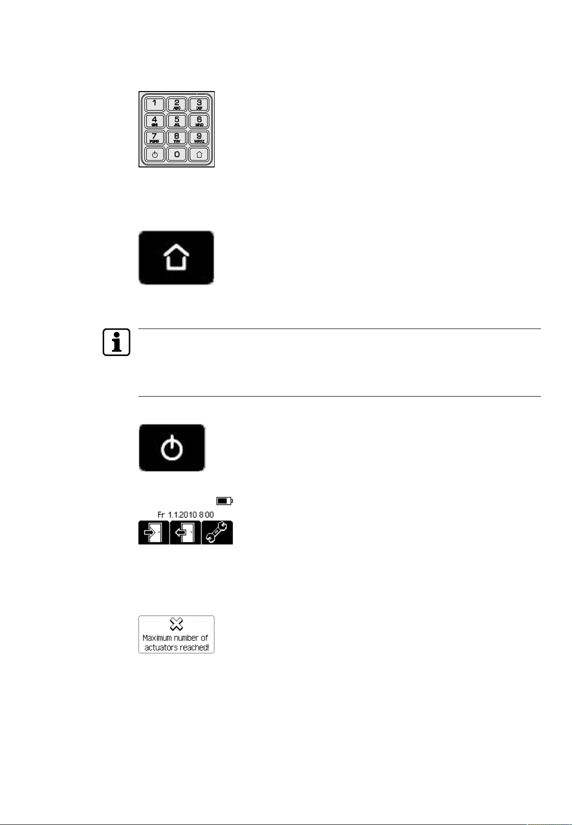
4.1.4 Alphanumeric buttons
Use the alphanumeric buttons to enter letters, digits and different signs.
4.1.5 Home button
The Home key always takes the user back to the previous menu (from every menu and
dialogue).
4.2 Switching on the programmer
If PIN protection is active, the PIN must be specified when switching on.
If an incorrect PIN is input 6 times in succession, the PIN and the locking plans on the
programmer are deleted.
• Further information on PIN protection can be found in the Chapter [}4.5.1.10].
1. Press the ON/OFF button for about two seconds.
—> The main menu is opened.
4.3 Display dialogues
During operation, the display shows a number of different dialogues with prompts and
messages.
1. Watch the display carefully during operation of the programmer.
2. Confirm the prompts and messages.
OperationUser Manual
13- 06/2021 dormakaba Programmer 1460

4.4 Wireless programming
During data transmission, never remove the programmer from the antenna panel of the
components (as otherwise transmission will abort).
The radio interface (NFC) is used for wireless programming and configuration.
For this, the programmer must be held with its front pointing directly at the component
antenna.
Example: c-lever
4.5 Settings
Different properties and settings can be adjusted in the Settings menu.
• Actuators
• Data
• Programmer
• Firmware update
• Emergency power supply
4.5.1 Programmer settings
1. Press the 'Settings' menu key.
2. Use the navigation keys to select the 'Programmer' menu.
3. Press the ENTER key.
ðThe properties are displayed.
Operation User Manual
14 - 06/2021dormakaba Programmer 1460

4.5.1.1 Setting the language
1. Open the 'Settings' menu.
2. Open the 'Programmer' menu.
3. Select the 'Language' entry.
4. Press the ENTER key.
5. Select the desired language from the list.
6. Press the ENTER key.
ðThe language setting is saved.
4.5.1.2 Setting the display contrast
1. Open the 'Settings' menu.
2. Open the 'Programmer' menu.
3. Choose the 'Contrast' sub-menu.
4. Press the ENTER key.
5. Select the desired contrast value using the navigation keys.
6. Press the ENTER key.
ðThe value is saved.
4.5.1.3 Setting the volume
1. Open the 'Settings' menu.
2. Open the 'Programmer' menu.
3. Choose the 'Volume' sub-menu.
4. Press the ENTER key.
5. Select the volume level using the navigation keys.
6. Press the ENTER key.
Note: The value < 1 means "mute".
ðThe value is saved.
OperationUser Manual
15- 06/2021 dormakaba Programmer 1460

4.5.1.4 Setting the date and time
Correctly set values for date and time ensure time management with the components is up-
to-date.
1. Open the 'Settings' menu.
2. Open the 'Programmer' menu.
3. Select the 'Date/Time' sub-menu.
4. Press the ENTER key.
ðThe cursor (flashes) shows the active position.
5. Enter the current date and time using the alphanumeric keys.
Note: Change the positions of the cursor using the navigation keys.
6. Press the ENTER key.
ðThe current values are saved.
4.5.1.5 Setting the lighting
1. Open the 'Settings' menu.
2. Open the 'Programmer' menu.
3. Choose the 'Lighting' sub-menu.
4. Press the ENTER key.
5. Select the lighting variant.
6. Press the ENTER key.
ðThe selection is saved.
Operation User Manual
16 - 06/2021dormakaba Programmer 1460

4.5.1.6 Setting the button tone
A warning always sounds when keys are pressed incorrectly.
1. Open the 'Settings' menu.
2. Open the 'Programmer' menu.
3. Choose the 'Key tone' sub-menu.
4. Press the ENTER key.
5. Select the desired property.
6. Press the ENTER key.
ðThe selection is saved.
4.5.1.7 Setting the switch-off time
Setting the optimum switch-off time enables the power consumption of the programmer to
be reduced and operation until the battery next requires charging to be prolonged.
1. Open the 'Settings' menu.
2. Open the 'Programmer' menu.
3. Select the 'Switch-off time' sub-menu.
4. Press the ENTER key.
5. Select the switch-off time.
6. Press the ENTER key.
ðThe selection is saved.
OperationUser Manual
17- 06/2021 dormakaba Programmer 1460

4.5.1.8 Entering a name
A restart is required to show a new name on the display.
1. Open the 'Settings' menu.
2. Open the 'Programmer' menu.
3. Select the 'Name' sub-menu.
4. Press the ENTER key.
Note: Use the right menu key (a/A) to switch between upper and lower case.
Use the left menu key (x) to delete a previous entry.
5. Enter a name using the alphanumeric keys (max. 28characters).
6. Press the ENTER key.
ðThe name is saved.
4.5.1.9 Info
1. Open the 'Settings' menu.
2. Open the 'Programmer' menu.
3. Select the menu option ‘Info’.
Programmer information is displayed:
SW Software version
CS Check sum
HW Hardware version
Press the ENTER key to exit the menu.
4.5.1.10 PIN protection
A PIN is set up on the Programmer for protection from unauthorised use. There is a prompt
for the PIN upon switching on the Programmer. The PIN does not have to be input any more
until the Programmer is switched off.
If a PIN has been set up through the system software, it is overwritten by the PIN set up with
the menu.
A PIN that has been set up through the menu of the Programmer cannot be changed by the
system software.
• The PIN can be set up using the system software as described in the system software
manual.
• The PIN is set up from the menu of the Programmer.
Setting up the PIN from the menu of the Programmer:
1. Select the menu ‘PIN Protection’.
2. Select the menu ‘Set PIN’.
3. Input the desired PIN twice.
ðIf both inputs match, the PIN is saved. PIN protection is active.
Change PIN:
If a PIN has been set up via the system software, it is to be input as the “old PIN”.
Operation User Manual
18 - 06/2021dormakaba Programmer 1460
1. Select the menu ‘PIN Protection’.
2. Select the menu ‘Change PIN’.
3. Input the old PIN.
4. Input the new PIN twice.
ðIf the inputs (old PIN, the new PIN twice) are not correct, the PIN is not changed.
Deleting the PIN and the locking plans on the Programmer:
Deleted key plans cannot be restored.
• Re-import the key plans.
1. Select the menu ‘Delete PIN’.
ðA confirmatory warning is displayed, asking whether the PIN and the locking plans on
the Programmer should be deleted.
2. Select ‘Yes’.
ðThe PIN and the locking plans are deleted on the Programmer.
4.5.1.11 Comfort update
In these settings, the programmer’s behaviour during a comfort update is determined.
In the 'Configuration' menu, you can select whether the configuration saved in the
component or in the programmer should be preferred during a firmware update.
In the 'Traceback' menu, you can select whether the traceback of the component should be
downloaded.
'Configuration' menu
1. Open the 'Settings' menu.
2. Open the 'Programmer' menu.
3. Open the 'Comfort update' menu.
4. Select the 'Configuration' sub-menu.
Select The user decides whether the existing configuration of a component
should be preferred over a configuration saved in the programmer.
Prefer internal The configuration of the component saved in the programmer is pre-
ferred.
Prefer existing The configuration saved in the component is preferred.
'Traceback' menu
1. Open the 'Settings' menu.
2. Open the 'Programmer' menu.
3. Open the 'Comfort update' menu.
4. Select the 'Traceback' sub-menu.
Select The user chooses for this firmware update.
Prefer internal The component traceback data saved in the programmer are pre-
ferred.
Prefer existing The traceback data saved in the component are preferred.
Do not read The traceback data are not read and are lost during update.
4.5.2 Actuator settings
Valid master media are required for some settings.
OperationUser Manual
19- 06/2021 dormakaba Programmer 1460

4.5.2.1 Setting the time
1. Open the 'Settings' menu.
2. Open the 'Actuator' menu.
3. Log in to the actuator using the master medium.
4. Connect the programmer to the actuator.
5. Choose the 'Set clock' sub-menu.
6. Press the ENTER key.
7. Select "Yes".
ðThe time is updated.
4.5.2.2 Battery change
In this menu, a time stamp is created for the battery change.
1. Open the 'Settings' menu.
2. Open the 'Actuator' menu.
3. Log in to the actuator using the master medium.
4. Connect the programmer to the actuator.
5. Select the 'Battery change' sub-menu.
6. Press the ENTER key.
7. Select "Yes" if a new battery has been placed.
Operation User Manual
20 - 06/2021dormakaba Programmer 1460
Table of contents


