DPA Solar Roof Mount User manual

DPA Solar Racking Solutions
Roof Mount Installation Guide
V1.3 (R2)

Roof Mount Installation Guide V1.3
Page 2 of 13
Please download the latest version of this document from www.dpasolar.com.au/support prior to commencing installation.
Under no circumstances shall DPA Solar be liable for special, indirect or consequential damages arising out of use of this product.
Introduction
DPA Solar racking when installed in accordance with this guide and applicable building
regulations will be structurally adequate and meet the requirements of AS/NZS1170.
It is important to note that the installer is responsible for the following:
•Complying with all applicable local or national building codes, including any that may
supersede this manual;
•Complying with all electrical, health and safety and other applicable regulations as
applicable to the location;
•Ensuring that DPA Solar racking and other products are appropriate for the particular
installation and the installation environment;
•Ensuring that the roof, its rafters, connections, and other structural support members can
support the array under building live load conditions;
•Ensuring that all screws and fixings have adequate pullout strength and shear capacities
as installed;
•Ensuring that loads other than wind are considered in the design. This document
addresses only wind loads on the assumption that wind produces the maximum load
factor affecting an installation. Verify that other local factors, such as snow loads and
earth quake effects, do not exceed the wind loads.
•Maintaining the waterproof integrity of the roof, including selection of appropriate
flashing;
•Fitting galvanic isolation where required to protect against dissimilar metals corrosion;
and
•Ensuring safe installation of all electrical aspects of the PV array.
This product is Warranted to be free from defective material and workmanship for a period of 10
years. Please visit www.dpasolar.com.au/support for full warranty details.

Roof Mount Installation Guide V1.3
Page 3 of 13
Please download the latest version of this document from www.dpasolar.com.au/support prior to commencing installation.
Under no circumstances shall DPA Solar be liable for special, indirect or consequential damages arising out of use of this product.
Planning
Wind regions as defined by Australian Standard 1170 are as follows:
•Most of Australia is designated Region A which indicates a Regional Ultimate Basic
Wind Velocity of 45m/sec.
•Some areas are designated Region B (57m/sec). Local authorities will advise if this
applies in your area.
•Region C areas (66m/sec) are generally referred to as Cyclonic and are generally limited
to northern coastal areas. Most Region C zones end 100km inland.
•Region D (80m/sec) Australia's worst Cyclonic Region between Carnarvon and Pardoo
in Western Australia.
This document applies to installations in regions A, B & C at roof heights of up to 10m
(three storeys). Region D sites require individual analysis and design.

Roof Mount Installation Guide V1.3
Page 4 of 13
Please download the latest version of this document from www.dpasolar.com.au/support prior to commencing installation.
Under no circumstances shall DPA Solar be liable for special, indirect or consequential damages arising out of use of this product.
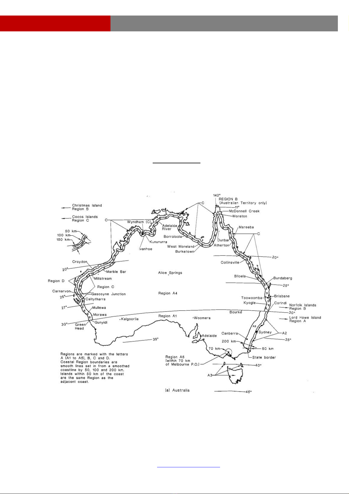
Terrain Categories are defined by Australian Standard 1170 into Categories 1, 2, 3 and 4.
Category 1, is the most exposed, associated with large open areas, such as airports or large
fields. Category 4, is the most protected, associated with High density metropolitan, city
buildings. This installation guide is applicable to Terrain Categories, as low as 2.5, hence no
greater exposure than the following scenarios, are allowed:
•Level wooded country / forests
•Centres of small towns, suburban areas
•High density metropolitan, city buildings
The wind force on the roof is dependant on the height of the roof. This factor is Mz,cat, as
defined by AS1170. To simplify different roof heights, single storey (height<4m), double storey
(height<7m), triple storey (height<10m), groups have been adopted. The roof height is
measured from natural ground level to the centre between ridge and eave. Other multipliers
such as Mt (topograghy) and Ms (shielding) have been adopted as 1.0. If topography is such
that Mt >1.0, spacings should be re-calculated, as those listed may not be sufficient. If shielding
is available, then Ms will only reduce, and the spans listed will become conservative.
The wind force on the roof is also dependant on the roof pitch (angle). The following tables, are
based on different angles (interpolation is allowed). The roof cladding is not a function of the
wind force applied to the roof. Tin roofs can be as low as 1 deg. Tiled roofs are limited to no
less than 15deg. Hence the tables, list options for 1-10,15,20,25,30-45 degrees.
An Exclusion Zone exists due to high localised wind pressures at roof ridges and edges. Solar
panels should not be installed in the exclusion zone where possible. If it is necessary to install
solar panels in the exclusion zone, then refer to especially listed distances between rail supports
for the length of rail that is within the exclusion zone. For roofs with pitch 10degrees or less (tin),
there is less overall force at the exclusion zone near the ridge, as the basic wind force reduces
along the length of the roof.
As the wind load co-efficients and exclusion zone are a function of h and d, it should be noted
that the following tables are also organized by (d<h) and (d>2h). For values in between,
interpolation is allowed. Breadth is generally not critical. Generally speaking, the (d<h) value is
appropriate for tall skinny buildings, and the (d>2h) value is appropriate for low level
construction.
The Exclusion Zone (marked as DIST in the diagram below) is defined as the minimum of:
•0.2d
•0.2b
•h
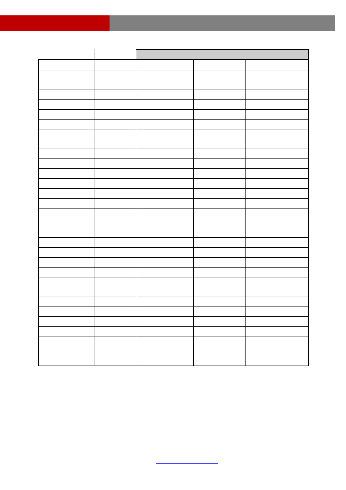
he following tables specify the maximum spacing between rail supports for tile or tin roofT
therinstallations. Maximum panel dimensions are 1400mm x 1100mm and weight 22kg. For o
panel sizes, refer to the “DPASolar Racking Worksheet” (Excel spreadsheet).

Roof Mount Installation Guide V1.3
Page 5 of 13
Please download the latest version of this document from www.dpasolar.com.au/support prior to commencing installation.
Under no circumstances shall DPA Solar be liable for special, indirect or consequential damages arising out of use of this product.
Rail Support Spacing – REGION A
Installation PITCH Edge Central Ridge
Single storey 1-10 (d<h) 900 1200 900
1-10 (d>2h) 1200 1800 1200
15 (d<h) 900 1200 900
15 (d>2h) 1200 1800 1200
20 (d<h) 1200 1800 1200
20 (d>2h) 1800 2400 1800
25 (d<h) 1200 2400 1200
25 (d>2h) 1800 2400 1800
30-45 (d<h) 1800 2400 1800
30-45 (d>2h) 2400 3000 2400
Double storey 1-10 (d<h) 900 1200 900
1-10 (d>2h) 1200 1800 1200
15 (d<h) 900 1200 900
15 (d>2h) 1200 1800 1200
20 (d<h) 1200 1800 1200
20 (d>2h) 1800 2400 1800
25 (d<h) 1200 1800 1200
25 (d>2h) 1800 2400 1800
30-45 (d<h) 1800 2400 1800
30-45 (d>2h) 2400 3000 2400
Triple storey 1-10 (d<h) 900 1200 900
1-10 (d>2h) 1200 1200 1200
15 (d<h) 900 1200 900
15 (d>2h) 1200 1800 1200
20 (d<h) 1200 1800 1200
20 (d>2h) 1800 2400 1800
25 (d<h) 1200 1800 1200
25 (d>2h) 1800 2400 1800
30-45 (d<h) 1800 2400 1800
30-45 (d>2h) 2400 2400 2400

Roof Mount Installation Guide V1.3
Page 6 of 13
Please download the latest version of this document from www.dpasolar.com.au/support prior to commencing installation.
Under no circumstances shall DPA Solar be liable for special, indirect or consequential damages arising out of use of this product.
Rail Support Spacing – REGION B
Installation PITCH Edge Central Ridge
Single storey 1-10 (d<h) 300 900 300
1-10 (d>2h) 600 900 600
15 (d<h) 600 900 600
15 (d>2h) 600 1200 600
20 (d<h) 600 1200 600
20 (d>2h) 900 1200 900
25 (d<h) 900 1200 900
25 (d>2h) 1200 1200 1200
30-45 (d<h) 1200 1200 1200
30-45 (d>2h) 1200 1800 1200
Double storey 1-10 (d<h) 300 900 300
1-10 (d>2h) 600 900 600
15 (d<h) 600 900 600
15 (d>2h) 600 1200 600
20 (d<h) 600 1200 600
20 (d>2h) 900 1200 900
25 (d<h) 900 1200 900
25 (d>2h) 1200 1200 1200
30-45 (d<h) 1200 1200 1200
30-45 (d>2h) 1200 1800 1200
Triple storey 1-10 (d<h) 300 600 300
1-10 (d>2h) 600 900 600
15 (d<h) 600 900 600
15 (d>2h) 600 1200 600
20 (d<h) 600 1200 600
20 (d>2h) 900 1200 900
25 (d<h) 900 1200 900
25 (d>2h) 1200 1200 1200
30-45 (d<h) 1200 1200 1200
30-45 (d>2h) 1200 1200 1200

Roof Mount Installation Guide V1.3
Page 7 of 13
Please download the latest version of this document from www.dpasolar.com.au/support prior to commencing installation.
Under no circumstances shall DPA Solar be liable for special, indirect or consequential damages arising out of use of this product.
Rail Support Spacing – REGION C
Installation PITCH Edge Central Ridge
Single storey 1-10 (d<h) 300 600 300
1-10 (d>2h) 300 600 300
15 (d<h) 300 600 300
15 (d>2h) 600 900 600
20 (d<h) 600 900 600
20 (d>2h) 600 900 600
25 (d<h) 600 900 600
25 (d>2h) 900 1200 900
30-45 (d<h) 900 1200 900
30-45 (d>2h) 900 1200 900
Double storey 1-10 (d<h) 300 600 300
1-10 (d>2h) 300 600 300
15 (d<h) 300 600 300
15 (d>2h) 600 900 600
20 (d<h) 600 900 600
20 (d>2h) 600 900 600
25 (d<h) 600 900 600
25 (d>2h) 900 1200 900
30-45 (d<h) 900 1200 900
30-45 (d>2h) 900 1200 900
Triple storey 1-10 (d<h) 300 600 300
1-10 (d>2h) 600 600 600
15 (d<h) 300 600 300
15 (d>2h) 600 600 600
20 (d<h) 600 600 600
20 (d>2h) 600 900 600
25 (d<h) 600 900 600
25 (d>2h) 900 900 900
30-45 (d<h) 900 900 900
30-45 (d>2h) 900 1200 900

Roof Mount Installation Guide V1.3
Page 8 of 13
Please download the latest version of this document from www.dpasolar.com.au/support prior to commencing installation.
Under no circumstances shall DPA Solar be liable for special, indirect or consequential damages arising out of use of this product.
Installation Steps
Determine the position of the roof hooks / L-feet according to the design requirements.
A = refer to tables on previous page
B = approximately 0.6x panel length
C = 375mm maximum overhang
1. Remove the roof tiles at the required positions or lift them up slightly.
A
B
C

Roof Mount Installation Guide V1.3
Page 9 of 13
Please download the latest version of this document from www.dpasolar.com.au/support prior to commencing installation.
Under no circumstances shall DPA Solar be liable for special, indirect or consequential damages arising out of use of this product.
2. Insert the roof hook to the wooden beam. Fix the roof hooks with screws (minimum
50mm penetration using 2 x Type 17 screws).
3. Replace tile. The roof hook must not press against the roof tile. If required shim the
roof hook with a spacer or grind the roof tile.
It is important not to use an installed roof hook as a ladder !
9
8

Roof Mount Installation Guide V1.3
Page 10 of 13
Please download the latest version of this document from www.dpasolar.com.au/support prior to commencing installation.
Under no circumstances shall DPA Solar be liable for special, indirect or consequential damages arising out of use of this product.
4. L feet installation. Ensure that there is adequate penetration of the screw into the
roof timber (minimum 50mm penetration using a Type 17 screw). Take care not to
crush or damage the roofing material by over-tightening the screw.
5. Install the rails onto the roof hooks / L feet loosely at first, then tighten. Ensure that
the T-screw is rotated and makes a secure mechanical connection before tightening
fully. Check again after tightening.

Roof Mount Installation Guide V1.3
Page 11 of 13
Please download the latest version of this document from www.dpasolar.com.au/support prior to commencing installation.
Under no circumstances shall DPA Solar be liable for special, indirect or consequential damages arising out of use of this product.
6. Install splices to connect multiple rails together. Slide the splice on the rear side of
the first rail. Fasten the first bolt firmly. Slide the next rail into the splice and fasten
the remaining bolt. Leave a gap about a finger width for expansion between the rails.

Roof Mount Installation Guide V1.3
Page 12 of 13
Please download the latest version of this document from www.dpasolar.com.au/support prior to commencing installation.
Under no circumstances shall DPA Solar be liable for special, indirect or consequential damages arising out of use of this product.
7. Install the solar PV modules starting from one end. Leave a space of 25 – 30mm at the
end of each rail.

Page 13 of 13
Please download the latest version of this document from www.dpasolar.com.au/support
Roof Mount Installation Guide V1.3
Arrange the panels so that there is approximately 20% overhang on each side of the rail.
Ensure that all end and mid clamps are securely fastened, and that all T-screws are
correctly rotated and locked against the rail.
prior to commencing installation.
Under no circumstances shall DPA Solar be liable for special, indirect or consequential damages arising out of use of this product.
Table of contents