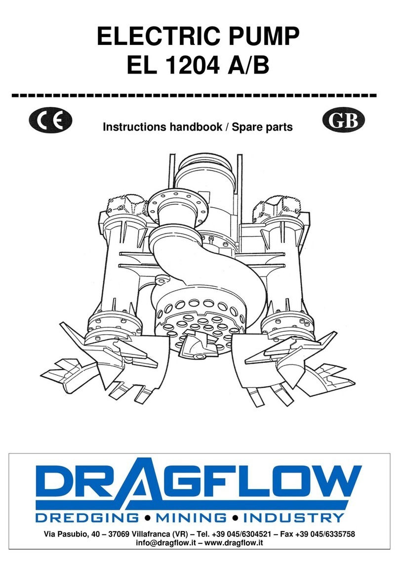
DRAGFLOW EL7.5 User manual

DRAGFLOW S.r.l. -Sede legale: Via Satiro, 11 –37121 VERONA Italy
Sedeamm.: ViaPaesa–46048ROVERBELLA (MN) Italy ● Tel. +39 03761685400
Fax+390376 1685499-Cod.Fisce P.IVA :IT02757460239 –R.E.A.Veronan.280092
Registro Impr. Di Verona n. 189595/1997 Capitale Sociale € 10.400 interamente versato
EL7.5 - EL12.5 (S - SS) User manual - ENG 1/70
EL7.5 - EL12.5 (S - SS)
USER MANUAL
USE - BASIC MAINTENANCE - SPARE PARTS

DRAGFLOW S.r.l. -Sede legale: Via Satiro, 11 –37121 VERONA Italy
Sedeamm.: ViaPaesa–46048ROVERBELLA (MN) Italy ● Tel. +39 03761685400
Fax+390376 1685499-Cod.Fisce P.IVA:IT02757460239 –R.E.A.Veronan.280092
Registro Impr. Di Verona n. 189595/1997 Capitale Sociale € 10.400 interamente versato
EL7.5 - EL12.5 (S - SS) User manual - ENG 2/70
DICHIARAZIONE DI CONFORMITA’ CE /
CE DECLARATION OF CONFORMITY
IL FABBRICANTE / THE MANUFACTURER
DRAGFLOW SRL
Via Paesa
46048 Roverbella (MN), Italy
DICHIARA CHE LA MACCHINA / DECLARES THAT THE MACHINE
Modello / Model :
EL
Matr. N. / Serial N. :
Anno / Year :
E’ CONFORME ALLE DIRETTIVE / CONFORMS TO THE DIRECTIVE(S)
Direttiva 2006/42/CE del Parlamento Europeo relativa alle macchine.
Directive 2006/42/EC of the European Parliament on machinery.
Direttiva 2014/30/EU del Parlamento Europeo concernente l’armonizzazione delle legislazioni degli Stati membri
relative alla compatibilità elettromagnetica.
Directive 2014/30/EU of the European Parliament on the harmonisation of the laws of the Member States relating to
electromagnetic compatibility.
Direttiva 2014/35/EU del Parlamento Europeo concernente l’armonizzazione delle legislazioni degli Stati membri
relative al materiale elettrico destinato ad essere adoperato entro taluni limiti di tensione.
Directive 2014/35/EU of the European Parliament on the harmonisation of the laws of the Member States relating to
electrical equipment designed for use within certain voltage limits.
Riferimento norme armonizzate / Reference standards:
EN 12100; EN 60204-1
E AUTORIZZA / AND IT AUTHORIZES
DRAGFLOW SRL
Via Paesa
46048 Roverbella (MN), Italy
A COSTITUIRE IL FASCICOLO TECNICO PER SUO CONTO /
TO FORM A TECHNICAL FILE FOR IT
Roverbella (MN), Italy –/ / Il fabbricante / The manufacturer
…………….……………………….

DRAGFLOW S.r.l. -Sede legale: Via Satiro, 11 –37121 VERONA Italy
Sedeamm.: ViaPaesa–46048ROVERBELLA (MN) Italy ● Tel. +39 03761685400
Fax+390376 1685499-Cod.Fisce P.IVA:IT02757460239 –R.E.A.Veronan.280092
Registro Impr. Di Verona n. 189595/1997 Capitale Sociale € 10.400 interamente versato
EL7.5 - EL12.5 (S - SS) User manual - ENG 3/70
CONTENTS
1. Introduction ............................................................................................ 7
1.1. Identification data............................................................................................ 7
1.2 General informations ....................................................................................... 8
1.2.1 Who is the manual intended for................................................................ 8
1.2.2 General symbols used ............................................................................... 9
1.2.3 Keeping the manual.................................................................................. 9
1.2.4 General safety rules and warnings.......................................................... 10
1.3 Technical specifications and reference standards ........................................... 11
1.4 Manufacturer's warranty................................................................................ 11
1.4.1 Warranty conditions ............................................................................... 12
1.4.2 Warranty exclusions ............................................................................... 13
1.4.3 Warranty duration.................................................................................. 13
1.5 Service Department........................................................................................ 14
1.6 How to read the manual................................................................................. 14
1.6.1 Numbering of figures and labels ............................................................. 14
1.7 Service manual............................................................................................... 14
2Description of the equipment ................................................................ 15
2.1 General characteristics ................................................................................... 15
2.1.1 Pump plate position................................................................................ 16
2.1.2 Dimensions and weight........................................................................... 16
2.1.3 Technical specifications........................................................................... 16
2.1.4 Electrical devices..................................................................................... 17
2.2 Intended use of the machine .......................................................................... 17
2.3 Safety of the operators................................................................................... 17
2.3.1 Operating areas and safety..................................................................... 18
3Transport, installation and dismantling .................................................. 19
3.1 Transport........................................................................................................ 19
3.2 Installation ..................................................................................................... 20

DRAGFLOW S.r.l. -Sede legale: Via Satiro, 11 –37121 VERONA Italy
Sedeamm.: ViaPaesa–46048ROVERBELLA (MN) Italy ● Tel. +39 03761685400
Fax+390376 1685499-Cod.Fisce P.IVA:IT02757460239 –R.E.A.Veronan.280092
Registro Impr. Di Verona n. 189595/1997 Capitale Sociale € 10.400 interamente versato
EL7.5 - EL12.5 (S - SS) User manual - ENG 4/70
3.2.1 Delivery pipe connecting......................................................................... 20
3.2.2 Connecting the power cable to the control box ....................................... 21
3.2.3 Connecting the power cable to the pump................................................ 21
3.3 Dismantling .................................................................................................... 22
4Operating instructions ........................................................................... 23
4.1 Before starting................................................................................................ 23
4.1.1 Before the first start................................................................................ 24
4.2 Starting........................................................................................................... 27
4.3 Working.......................................................................................................... 27
4.4 Stopping......................................................................................................... 27
4.5 Emergency situation....................................................................................... 27
5Maintenance ......................................................................................... 29
5.1 General information....................................................................................... 29
5.1.1 Tools for ordinary maintenance .............................................................. 29
5.1.2 Bolts tightening torque ........................................................................... 32
5.1.3 Lubricants specifications ......................................................................... 33
5.1.4 Exploded view and pump's groups .......................................................... 34
5.2 Maintenance schedule ................................................................................... 35
5.2.1 Before every shift.................................................................................... 36
5.2.2 After every shift ...................................................................................... 36
5.2.3During every shift ................................................................................... 36
5.2.4 Every 8 operating hours .......................................................................... 37
5.2.5 Every 50 operating hours ........................................................................ 37
5.2.6 Every 150 operating hours ...................................................................... 37
5.3 Maintenance operating instructions............................................................... 38
5.3.1 Lubricating oil checking........................................................................... 38
5.3.2 Lubricating oil changing/refilling ............................................................ 39
5.3.3 Impeller clearence checking .................................................................... 40
5.3.4 Impeller clearence adjusting ................................................................... 41
5.4 Maintenance replacing instructions................................................................ 44
5.4.1 Power cable ............................................................................................ 45

DRAGFLOW S.r.l. -Sede legale: Via Satiro, 11 –37121 VERONA Italy
Sedeamm.: ViaPaesa–46048ROVERBELLA (MN) Italy ● Tel. +39 03761685400
Fax+390376 1685499-Cod.Fisce P.IVA:IT02757460239 –R.E.A.Veronan.280092
Registro Impr. Di Verona n. 189595/1997 Capitale Sociale € 10.400 interamente versato
EL7.5 - EL12.5 (S - SS) User manual - ENG 5/70
5.4.2 Strainer................................................................................................... 45
5.4.3 Lower wear plate.................................................................................... 47
5.4.4 Agitator kit ............................................................................................. 49
5.4.5 Impeller .................................................................................................. 50
5.4.6 Motor bearing ........................................................................................ 51
5.4.7 Lower seals ............................................................................................. 51
5.4.8 Mechanical seals..................................................................................... 51
5.4.9 Upper bearings ....................................................................................... 51
5.4.10 O-ring replacing...................................................................................... 51
6Spare parts ............................................................................................ 52
6.1 Exploded views............................................................................................... 52
6.1.1 Electric motor group ............................................................................... 52
6.1.2 Oil chamber group .................................................................................. 55
6.1.3Impeller kit ............................................................................................. 59
6.1.4 Agitator kit ............................................................................................. 60
6.2 Spare parts list................................................................................................ 61
6.2.1 Specific parts list for EL7.5 - EL7.5S - EL7.5SS ........................................... 61
6.2.2 Specific parts list for EL10 - EL10S - EL10SS .............................................. 61
6.2.3 Specific parts list for EL12.5 - EL12.5S - EL12.5SS ..................................... 61
6.2.4 Common parts list................................................................................... 62
6.2.5 Suggested spare parts............................................................................. 63
7Optional devices .................................................................................... 64
7.1 Jet-ring system ............................................................................................... 64
7.1.1 Spare parts ............................................................................................. 64
7.2 Compensation system .................................................................................... 65
7.2.1 Spare parts ............................................................................................. 65
7.3 Temperature sensor ....................................................................................... 66
7.3.1 Spare parts ............................................................................................. 66
7.4 Water sensor.................................................................................................. 67
7.5 Cooling jacket................................................................................................. 67
7.6 Cutter knife .................................................................................................... 67

DRAGFLOW S.r.l. -Sede legale: Via Satiro, 11 –37121 VERONA Italy
Sedeamm.: ViaPaesa–46048ROVERBELLA (MN) Italy ● Tel. +39 03761685400
Fax+390376 1685499-Cod.Fisce P.IVA:IT02757460239 –R.E.A.Veronan.280092
Registro Impr. Di Verona n. 189595/1997 Capitale Sociale € 10.400 interamente versato
EL7.5 - EL12.5 (S - SS) User manual - ENG 6/70
7.6.1 Spare parts ............................................................................................. 67
7.7 Aggressive environment kit ............................................................................ 68
7.7.1 Spare parts ............................................................................................. 68
7.8 Waterflush kit ................................................................................................ 69
7.9 Remote greasing kit........................................................................................ 69
7.10 Optional on this pump.................................................................................... 69
8Attachments.......................................................................................... 70
8.1 Data sheet and performance curves ............................................................... 70

DRAGFLOW S.r.l. -Sede legale: Via Satiro, 11 –37121 VERONA Italy
Sedeamm.: ViaPaesa–46048ROVERBELLA (MN) Italy ● Tel. +39 03761685400
Fax+390376 1685499-Cod.Fisce P.IVA:IT02757460239 –R.E.A.Veronan.280092
Registro Impr. Di Verona n. 189595/1997 Capitale Sociale € 10.400 interamente versato
EL7.5 - EL12.5 (S - SS) User manual - ENG 7/70
1. Introduction
1.1. Identification data
Read in the following the name and address of the machine manufacturer:
DRAGFLOW S.r.l.
Via Paesa
46048 –Roverbella (MN) ITALY
www.dragflow.it
Each machine is equipped with an identification plate that ensures it is produced
according to all the European directives in force and the necessary safety requirements.
This conformity is certified and is present on the respective identification plate bearing
the "EC" marking.
The model, serial number, year of construction are enclosed on the plate placed on the
main body of the machine. This data must be mentioned whenever a request for
information regarding the machinery is forwarded or for ordering replacement parts.
We recommend to provide, when possible, the following data:
- working hours of the equipment;
- purchase date;
- detailed information on any problems found.
Genuine parts should be used for the replacement of parts of the machine.
The manufacturer declines any responsibility regarding any worsening of performance
or damage to the machine or equipment, due to the use of non-genuine spare parts.

DRAGFLOW S.r.l. -Sede legale: Via Satiro, 11 –37121 VERONA Italy
Sedeamm.: ViaPaesa–46048ROVERBELLA (MN) Italy ● Tel. +39 03761685400
Fax+390376 1685499-Cod.Fisce P.IVA:IT02757460239 –R.E.A.Veronan.280092
Registro Impr. Di Verona n. 189595/1997 Capitale Sociale € 10.400 interamente versato
EL7.5 - EL12.5 (S - SS) User manual - ENG 8/70
1.2 General informations
This manual should be carefully consulted and understood because it contains
important information for the safety of operators during the machine use.
In case of doubt or uncertainty on the information provided in this manual please
contact the manufacturer for clarifiction.
However, the machine is intended suitable for uses which is expressly designed for,
produced and placed on the market. Any different use must be considered inappropriate
and therefore unsafety.
Any contractual or non-contractual liability of the manufacturer shall be excluded for
failures and damages caused by errors in the handling and use of the equipment not
compling with the instructions given by the manufacturer.
The manual translations from the original language (italian), may be inaccurate or
express unintentionally different concepts, therefore refer to the version in the original
language or contact the manufacturer for any clarification.
1.2.1 Who is the manual intended for
This manual must be read by any operator in charge of installing and using the
machine for the intended purposes it was designed, produced and placed on the
market.
The operator wording refers to a person without a specific skill, but able to perform
safetely the following activities:
- handling of loads (also suspended) with lifting devices such as fork lift or hoist;
- mechanical operation such as simple assembling and adjusting;
- cables wiring for disconnected electrical devices;
- machines using with commands and controls on electric panel and suitably
described by labels;
- machines using when they are in safety condition with all the provided safety
devides in perfect condition, properly installed and completely operative.
The operator must also have basic general culture and technical basic culture to
sufficiently read and understand the contents of the manual, including the correct
interpretation of images, drawings and pictograms.
It is the responsibility of the user of the machine to ensure the listed operator
requirements and to be trained about the health and safety standards in force in the
country where the machine is working.

DRAGFLOW S.r.l. -Sede legale: Via Satiro, 11 –37121 VERONA Italy
Sedeamm.: ViaPaesa–46048ROVERBELLA (MN) Italy ● Tel. +39 03761685400
Fax+390376 1685499-Cod.Fisce P.IVA:IT02757460239 –R.E.A.Veronan.280092
Registro Impr. Di Verona n. 189595/1997 Capitale Sociale € 10.400 interamente versato
EL7.5 - EL12.5 (S - SS) User manual - ENG 9/70
1.2.2 General symbols used
The following symbols (Tab. 1) are used within the manual to highlight those
operations and instructions particularly relevant.
SYMBOL
MEANINGS
DANGER: any situation/instruction that
involve personnel's safety and that can result
in serious injury or death.
ATTENTION: any situation/instruction that
involve the machine integrity, but which do
not affect the safety of people.
IMPORTANT: any important information or
practical advice that affect neither the
personal safety nor the machine integrity
RESPECT THE ENVIRONMENT: any important
information for the protection of the
environment
Tab. 1
1.2.3 Keeping the manual
The user manual represents an essential and integral part of the equipment and must
be delivered to the user.
It must be carefully kept in a clean place, protected from any predictable agent/event
able to damage it.

DRAGFLOW S.r.l. -Sede legale: Via Satiro, 11 –37121 VERONA Italy
Sedeamm.: ViaPaesa–46048ROVERBELLA (MN) Italy ● Tel. +39 03761685400
Fax+390376 1685499-Cod.Fisce P.IVA:IT02757460239 –R.E.A.Veronan.280092
Registro Impr. Di Verona n. 189595/1997 Capitale Sociale € 10.400 interamente versato
EL7.5 - EL12.5 (S - SS) User manual - ENG 10/70
1.2.4 General safety rules and warnings
The manufacturer ensures the utmost commitment to make the equipment as safe
as possible, providing it with all the guards and safety devices deemed necessary.
Finally, the equipment has been accompanied with all the sufficient information to be
used safely and correctly.
Do not allow non-qualified operator to use the
machine.
Before beginning any operation on the
machine, the operator must be aware of the
location and meaning of all commands and
controls.
Before beginning any operation on the
machine, make sure that all the guards and
protections are correctly installed, in perfect
condition and completely efficient.
During the working operations, the operator
must be provided of the suitable personal
protective equipment.
It's responsability of the user to determine the working condition during the machine
use and consequently decide the required personal protective equipment.
Any suggestion given in this manual about a personal protective equipment use does
not replace the mentioned obligation on the part of the user.
Use the equipment within the limits indicated
in the technical specifications.

DRAGFLOW S.r.l. -Sede legale: Via Satiro, 11 –37121 VERONA Italy
Sedeamm.: ViaPaesa–46048ROVERBELLA (MN) Italy ● Tel. +39 03761685400
Fax+390376 1685499-Cod.Fisce P.IVA:IT02757460239 –R.E.A.Veronan.280092
Registro Impr. Di Verona n. 189595/1997 Capitale Sociale € 10.400 interamente versato
EL7.5 - EL12.5 (S - SS) User manual - ENG 11/70
1.3 Technical specifications and reference standards
The equipment has been designed and built based on the customer's specific requests,
defined within the contract. Nevertheless any machine is designed, produced and placed
on the market by the manufacturer in compliance with all the required standard in force
UE during the period of manufacture.
See below the reference standards (if applicable) for the machine:
- Machinery Directive 2006/42/EC;
- Directive 2014/35/EU concerning the safety for the electrical equipment used
under "low voltage";
- Directive 2014/30/EU on electromagnetic compatibility;
- Directive 2014/68/EU on equipment with components under pressure;
- Standard ISO 898-1: 2013 for mechanical fastening;
- Standard ISO 12151-1: 2017 for hydraulic fittings.

DRAGFLOW S.r.l. -Sede legale: Via Satiro, 11 –37121 VERONA Italy
Sedeamm.: ViaPaesa–46048ROVERBELLA (MN) Italy ● Tel. +39 03761685400
Fax+390376 1685499-Cod.Fisce P.IVA:IT02757460239 –R.E.A.Veronan.280092
Registro Impr. Di Verona n. 189595/1997 Capitale Sociale € 10.400 interamente versato
EL7.5 - EL12.5 (S - SS) User manual - ENG 12/70
1.4 Manufacturer's warranty
The manufacturer guarantees the original user that the machine will be reasonably free
from factory and material defects.
In case of unpredictable defects, the user can claim the warranty.
Any warranty request must be recognized by the manufacturer as being subject to the
warranty conditions after presentation of adequate proof of claim, and eventually
accepted in one of the following ways, at the discretion of the manufacturer:
- replacement of defective part with a new one, made available in the offices of the
purchaser at the lowest transport rate;
- repair of defective part, after this has been returned to the manufacturer with
transport expenses prepaid.
In the first case, as soon as the new spare is ready, the user will make the defective part
available to the manufacturer workshop for inspection.
The manufacturer declines all responsability for the expenses due to “down time”,
business costs and losses deriving from faults and failure, even if under warranty
conditions.
Any claim for warrantable failures shall be sent in writing to the manufacturer prior to
the expiry of the warranty period.
This warranty is the sole warranty provided by the manufacturer.
There are no other warranties, explicit or implied, provided by the manufacturer.
1.4.1 Warranty conditions
The warranty does not apply to those parts that result defective because of incorrect
use and handling or bad observance of the use and maintenance instructions supplied
by the manufacturer.
The warranty completely expires as soon as non genuine spare parts are installed on the
equipment without the manufacturer permission.
The warranty on the electric motor and other warrantable components damaged due
to electric faults is applied only if the power supplying devices installed (power
generator, power cable, electric/control panel) are supplied by the manufacturer and
are specifically suitable for the present machine.
If the user tries, either to repair by his own any fault that is under guarantee or to use
spare parts not supplied directly by the manufacturer without his previous written
consent, the latter will not be responsible for the results of the repair and will not be
held to reimburse the expenses sustained by the user.

DRAGFLOW S.r.l. -Sede legale: Via Satiro, 11 –37121 VERONA Italy
Sedeamm.: ViaPaesa–46048ROVERBELLA (MN) Italy ● Tel. +39 03761685400
Fax+390376 1685499-Cod.Fisce P.IVA:IT02757460239 –R.E.A.Veronan.280092
Registro Impr. Di Verona n. 189595/1997 Capitale Sociale € 10.400 interamente versato
EL7.5 - EL12.5 (S - SS) User manual - ENG 13/70
1.4.2 Warranty exclusions
The warranty is not applied for the following listed parts subject to usual wearing:
- gaskets and sealing components;
- shaft sleeves;
- impeller kit;
- agitator kit;
- upper/lower wear plates;
- casing;
- strainer
- discharge adapter;
- any other component directly in contact with the dredge material flow.
The warranty is not applicable to the following electric components:
- power cables (when supplied);
- terminal board.
The warranty is not applicable to any consequential damage due to the failure under
warranty claim.
1.4.3 Warranty duration
The warranty lasts for 1 year from the delivery date specified in the contract.
If the contract condition foresees the machine start-up performed by a manufacturer
techinician, the duration of guarantee is 12 months from the start-up date and in any
case not over 16 months from the delivery date specified in the contract.

DRAGFLOW S.r.l. -Sede legale: Via Satiro, 11 –37121 VERONA Italy
Sedeamm.: ViaPaesa–46048ROVERBELLA (MN) Italy ● Tel. +39 03761685400
Fax+390376 1685499-Cod.Fisce P.IVA:IT02757460239 –R.E.A.Veronan.280092
Registro Impr. Di Verona n. 189595/1997 Capitale Sociale € 10.400 interamente versato
EL7.5 - EL12.5 (S - SS) User manual - ENG 14/70
1.5 Service Department
For any inconvenient or technical request, please contact the manufacturer Service
Department on:
tel.+39 0376 1685400
fax +39 0376 1685499
To locate a specific component of the equipment please refer to the diagrams and the
exploded views contained in this manual.
Always refer to the sections of the manual dedicated to the use and maintenance.
Contact the Service Department if it is not possible to solve the problem on site by your
own.
1.6 How to read the manual
For a correct reading and consultation, this documentation has been conveniently
divided into chapters. They are listed in the general index.
Some picture may not represent exactly the equipment with differences that anyway
don’t affect the accuracy of the given information.
1.6.1 Numbering of figures and labels
Each figure and table included in the manual is numbered in a progressive manner,
chapter by chapter.
Any label inside the figures could be a number, only when referred directly to a
position of the pump parts list, or letter.
1.7 Service manual
This manual provides instructions for the use and the basic maintenance of the machine,
concerning activities normally achievable in a generic environment.
Any other maintemance activities require to be performed in a workshop. In this case,
refer to the Service Department or to the Service Manual (available on request) for
assistance and instructions.

DRAGFLOW S.r.l. -Sede legale: Via Satiro, 11 –37121 VERONA Italy
Sedeamm.: ViaPaesa–46048ROVERBELLA (MN) Italy ● Tel. +39 03761685400
Fax+390376 1685499-Cod.Fisce P.IVA:IT02757460239 –R.E.A.Veronan.280092
Registro Impr. Di Verona n. 189595/1997 Capitale Sociale € 10.400 interamente versato
EL7.5 - EL12.5 (S - SS) User manual - ENG 15/70
2 Description of the equipment
2.1 General characteristics
The electric motor driven pump (Fig. 1) is made up of a cylindrical motor housing [3]
inside of which is located an electrical motor [B]. The upper support [40]is completely
water-tight, and contains the terminal box for connection to the electric motor; the
waterproofing is guaranteed by the cover and by a series of seals [D]. Inside the oil
chamber/casing [4] is located the group of mechanical seals [F] that prevents the water
from passing to the motor.
On the main shaft [2], inside the oil chamber/casing [4] there is a keyed impeller [1],
made in high chrome content anti-wear materials. A lower wear plate [7], made with
the same material, partially closes the impeller inlet. Inside the strainer protection [50]
houses an agitator [10]that rotates and stirs the mixture of solids in the water to be
pumped.
Fig. 1
[3]
[B]
[40]
]
[D]
[4]
[1]
[7]
[50]
[10]
[F]
[2]

DRAGFLOW S.r.l. -Sede legale: Via Satiro, 11 –37121 VERONA Italy
Sedeamm.: ViaPaesa–46048ROVERBELLA (MN) Italy ● Tel. +39 03761685400
Fax+390376 1685499-Cod.Fisce P.IVA:IT02757460239 –R.E.A.Veronan.280092
Registro Impr. Di Verona n. 189595/1997 Capitale Sociale € 10.400 interamente versato
EL7.5 - EL12.5 (S - SS) User manual - ENG 16/70
2.1.1 Pump plate position
See Fig. 2 for the position of the machine identification plate.
Fig. 2
The electric data AMP (current absorbment)
and HP/KW (power) indicate the maximum
values. Never exceed these values during
continuous operation.
The electric data VOLT (voltage) indicates a
nominal value. Never exceed a 10% variation
of these value during continuous operation.
2.1.2 Dimensions and weight
Refer to the data-sheet of the pump (see chapter Attachments) for overall
dimensions and weight.
2.1.3 Technical specifications
Refer to the data-sheet of the pump (see chapter Attachments) for any technical
specifications (performance, materials, plate data).

DRAGFLOW S.r.l. -Sede legale: Via Satiro, 11 –37121 VERONA Italy
Sedeamm.: ViaPaesa–46048ROVERBELLA (MN) Italy ● Tel. +39 03761685400
Fax+390376 1685499-Cod.Fisce P.IVA:IT02757460239 –R.E.A.Veronan.280092
Registro Impr. Di Verona n. 189595/1997 Capitale Sociale € 10.400 interamente versato
EL7.5 - EL12.5 (S - SS) User manual - ENG 17/70
2.1.4 Electrical devices
The pump cannot operate without previous connecting to a power source (such as
power generator) and a control panel.
Before using the pump, take care that all these electric devices are suitable to the
electric specification of the machine (see the machine plate and data-sheet) and meet
the related international standars, expecially about the safety of the operator and the
safeguard of the equipment.
The pump is not provided of an Emergency Stop button on board. Any electrical
system used for the power supply of the pump must be provided with the Emergency
Stop button.
The Emergency Stop button must stop instantly any electrical connection to the pump
after pushing and must keep the pump disconnected without resetting. After
resetting the Emergency Stop button, the pump cannot start automatically.
2.2 Intended use of the machine
The machine is designed produced and placed on the market for dredging operations,
that is pumping underwater a mixture of water and solid materials (sand, mud, rocks of
suitable dimensions) with density variable depending on the working condition.
2.3 Safety of the operators
The machine has been designed and produced with all the possible precautions to carry
out dredging operations under the utmost safety conditions, considering the current
state-of-the-art for this kind of equipment.
Before beginning any operation on the
machine, the operator must be aware of the
location and meaning of all commands and
controls.
Before beginning any operation on the
machine, make sure that all the guards and
protections are correctly installed, in perfect
condition and completely efficient.
During the working operations, the operator
must be provided of the suitable personal
protective equipment.
During dredging operations, the operator
must stay near the control panel and no one
must remains close to the dredging area.

DRAGFLOW S.r.l. -Sede legale: Via Satiro, 11 –37121 VERONA Italy
Sedeamm.: ViaPaesa–46048ROVERBELLA (MN) Italy ● Tel. +39 03761685400
Fax+390376 1685499-Cod.Fisce P.IVA:IT02757460239 –R.E.A.Veronan.280092
Registro Impr. Di Verona n. 189595/1997 Capitale Sociale € 10.400 interamente versato
EL7.5 - EL12.5 (S - SS) User manual - ENG 18/70
However, the best approach to avoid risks and prevent the damages is to use the
equipment exclusively for the intended use with expertise and caution.
Remember the followings:
- read with care and completely the present manual and the annexes, if present;
- don't hesitate to contact the Service Department of the manufacturer in case of
doubt or need;
- before every use, check carefully the integrity of the equipment and all its
components, with care for safety and lifting equipment.
2.3.1 Operating areas and safety
The operating area for the operator of the machine is close to the control panel.
During working operation, the machine is placed underwater and the operator must
stay in the defined operating area. No one must remains close to the dredging area.
The control panel must be placed in a dry and clean position. Take care that the
control panel is closed and every access inside it is denied without shutting down the
electric power.
During maintenance operation, the machine could be placed out of water. In this
occasion, operate on the machine only with the electric power shut down.
Don’t touch the machine if the electric power
is on.
During maintenance operation, starting the machine out of water could be required.
In this occasion, any person must stay at a safety distance from the machine (not less
than 2 meters) in a dry and clean place. Before starting in this condition, check that
the machine is clean, specially its rotating components.

DRAGFLOW S.r.l. -Sede legale: Via Satiro, 11 –37121 VERONA Italy
Sedeamm.: ViaPaesa–46048ROVERBELLA (MN) Italy ● Tel. +39 03761685400
Fax+390376 1685499-Cod.Fisce P.IVA:IT02757460239 –R.E.A.Veronan.280092
Registro Impr. Di Verona n. 189595/1997 Capitale Sociale € 10.400 interamente versato
EL7.5 - EL12.5 (S - SS) User manual - ENG 19/70
3 Transport, installation and dismantling
3.1 Transport
The pump is generally supplied encased inside a crate to avoid damage during transport.
The crate is arranged for moving with a fork-lift truck (Fig. 3), whose capacity must be
able to sustain the weight of the machine (see data sheet enclosed in the Attachment
chapter). The pump is provided with lifting point (A) as shown in Fig.3. Use this lifting
point to move and position the pump.
Fig. 3
After checking the weight of the machine, use
adequate lifting equipment to move and
position it.
Check the condition of the lifting point before
every lifting and moving operation.

DRAGFLOW S.r.l. -Sede legale: Via Satiro, 11 –37121 VERONA Italy
Sedeamm.: ViaPaesa–46048ROVERBELLA (MN) Italy ● Tel. +39 03761685400
Fax+390376 1685499-Cod.Fisce P.IVA:IT02757460239 –R.E.A.Veronan.280092
Registro Impr. Di Verona n. 189595/1997 Capitale Sociale € 10.400 interamente versato
EL7.5 - EL12.5 (S - SS) User manual - ENG 20/70
3.2 Installation
The installation of the pump requires to be performed by a operator skilled on
suspended loads handling, mechanical assembling and electrical wiring.
Some operations shoud be performed in
enviroment with deep water risks, wet
surfaces risks, suspended loads risks and
handling loads risks with danger of drowning,
slipping, crushing and trapping. Wear
appropriate safety personal protective
equipment.
3.2.1 Delivery pipe connecting
Connect the delivery pipe to the exit flange of the pump. Refer to the data-sheet (see
chapter Attachments) for the correct size of the connections.
The delivery pipes must never form siphons (Fig. 4) to avoid problems due to the
formation of air pockets or deposits of solid material.
Fig. 4
This manual suits for next models
1
Table of contents
Other DRAGFLOW Water Pump manuals
Popular Water Pump manuals by other brands

CVS
CVS VacuStar WR 2500 operating instructions

Levitronix
Levitronix BPS-i100 user manual

Agilent Technologies
Agilent Technologies VacIon Plus 20 user manual

ekwb
ekwb EK-XRES SPC Series INSTALLATION AND MOUNTING MANUAL

Gotec
Gotec RAPIDO instruction manual

Central Machinery
Central Machinery 47906 Assembly and operating instructions