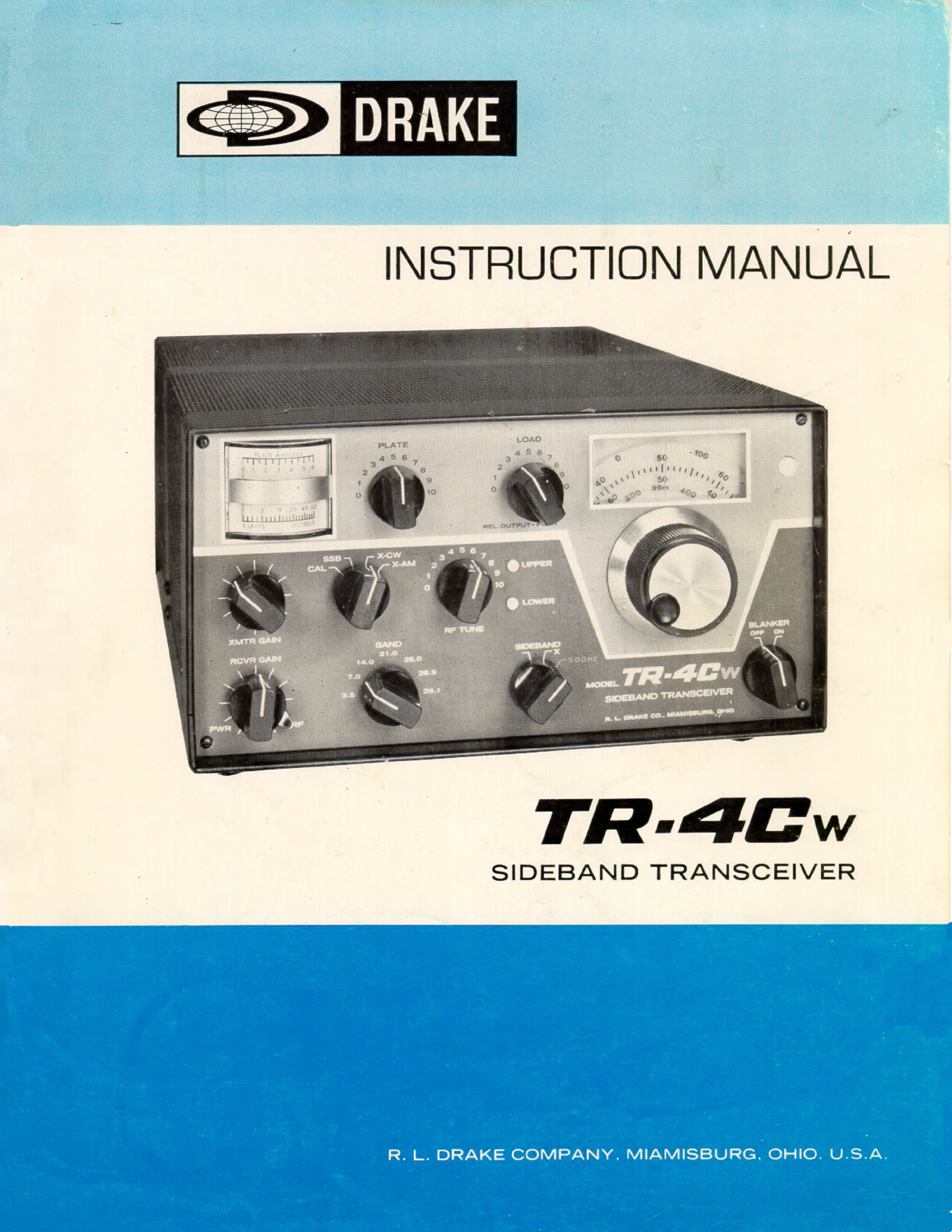
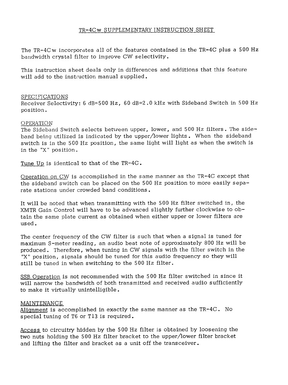
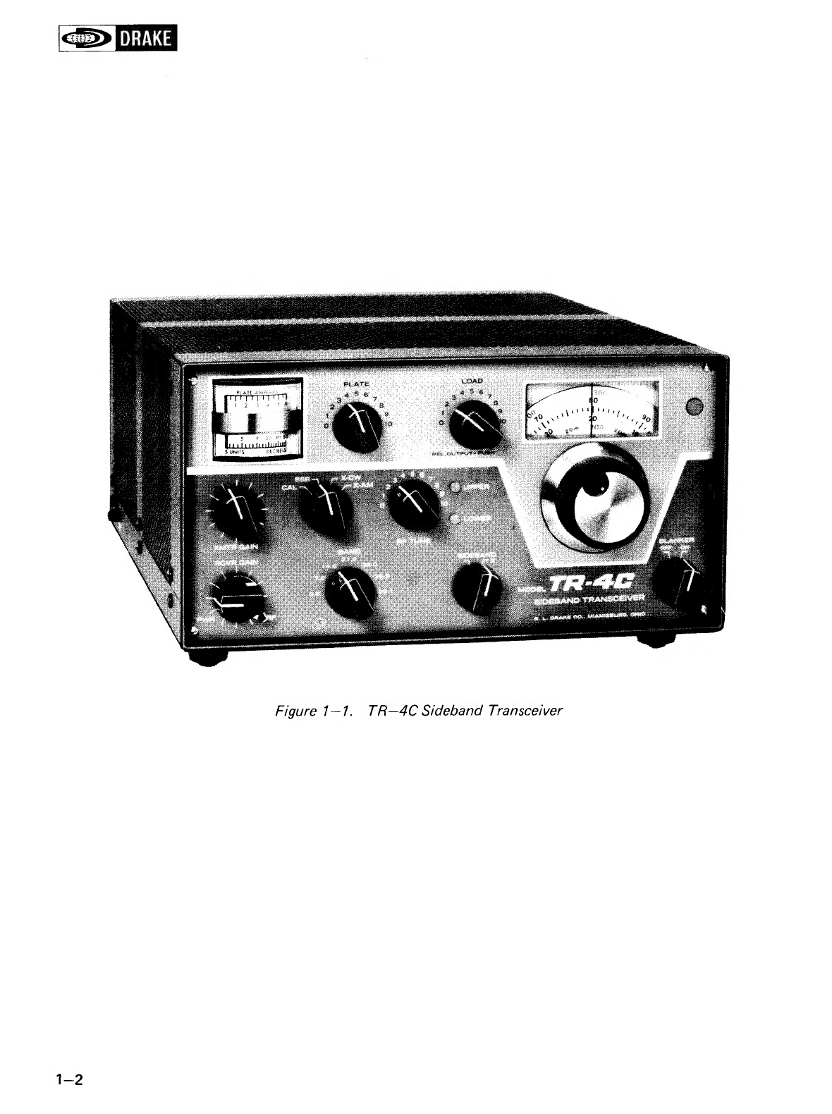
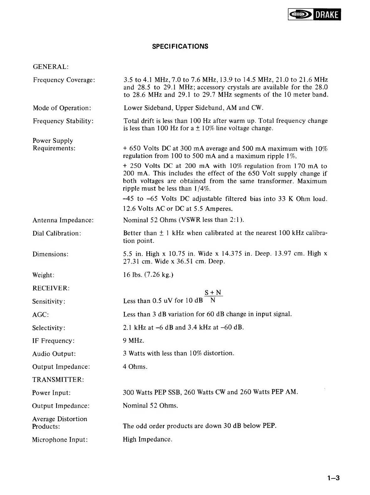
DRAKE TR-4CW User manual

DRAK
INSTRUCTION
MANUAL
SIDEBAND
TRANSCEIVER

DRAKE
LIMITED
WARRANTY
R.L.
DRAKE
COMPANY
warrants
to
the
original
purchaser
that
this
product
shall
be
free
from
defects
in
material
(except
tubes
and
RF
output
transistors)
or
workmanship
for
ninety
(90)
days
from
the
date
of
original
purchase.
During
the
warranty
period
the
R.
L.
DRAKE
COMPANY
or
an
authorized
Drake
service
facility
will
provide
free
of
charge
both
parts
(except
tubes
and
RF
output
transistors)
and
labor
necessary
to
correct
defects
in
material
or
workmanship.
To
obtain
such
warranty
service,
the
original
purchaser
must:
(1)
Complete
and
send
in
the
Warranty
Registration
Card.
(2)
Notify
R.
L.
DRAKE
COMPANY
or
its
nearest
authorized
service
facility,
as
soon
as
possible
after
discovery
of
a
possible
defect,
of:
(a)
The
model
number
and
serial
number,
if
any;
(b)
The
identity
of
the
seller
and
the
approximate
date
of
purchase;
(c)
A
detailed
description
of
the
problem,
including
details
on
the
electrical
connection
to
associated
equipment
and
the
list
of
such
equipment.
(3)
Deliver
the
product
to
the
R.
L.
DRAKE
COMPANY
or
the
nearest
authorized
service
facility,
or
ship
the
same
in
its
original
container
or
equivalent,
fully
insured
and
ship-
ping
charges
prepaid.
Correct
maintenance,
repair
and
use are
important
to
obtain
proper
performance
from
this
product.
Therefore,
carefully
read
the
Instruction
Manual.
This
warranty
does
not
apply
to
any
defect
that
R.
L.
DRAKE
COMPANY
determines
is
due
to:
(1)
Improper
maintenance
or
repair,
including
the
installation
of
parts
or
accessories
that
do
not
conform
to
the
quality
and
specifications
of
the
original
parts.
(2)
Misuse,
abuse,
neglect
or
improper
installation.
(3)
Accidental
or
intentional
damage.
All
implied
warranties,
if
any,
terminate
ninety
(90)
days
from
the
date
of
the
original
purchase.
The
foregoing
constitutes
R.
L.
DRAKE
COMPANY’S
entire
obligation
with
respect
to
this
product,
and
the
original
purchaser
and
any
user
or
owner
shall
have
no
other
remedy
and
no
claim
for
incidental
or
consequential
damages.
Some
states
do
not
allow
limitations
on
how
long
an
implied
warranty
lasts
or
do
not
allow
the
exclusion
or
limitation
of
incidental
or
consequential
damages,
so
the
above
limitation
and
exclusion
may
not
apply
to
you.
This
warranty
gives
specific
legal
rights
and
you
may
also
have
other
rights
which
vary
from
State
to
State.
R.
L.
DRAKE
COMPANY
540
Richard
Street
«
Miamisburg,
Ohio
45342
DRAKE
PRINTED
IN
U.S.A,

TR-4C
w_
SUPPLEMENTARY
INSTRUCTION
SHEET
The
TR-4Cw
incorporates
all
of
the
features
contained
in
the
TR-4C
plus
a
500
Hz
bandwidth
crystal
filter
to
improve
CW
selectivity.
This
instruction
sheet
deals
only
in
differences
and
additions
that
this
feature
will
add
to
the
instruction
manual
supplied.
SPECIFICATIONS
Receiver
Selectivity:
6
dB=500
Hz,
60
dB=2.0
kHz
with
Sideband
Switch
in
500
Hz
position.
OPERATION
The
Sideband
Switch
selects
between
upper,
lower,
and
500
Hz
filters.
The
side-
band
being
utilized
is
indicated
by
the
upper/lower
lights.
When
the
sideband
switch
is
in
the
500
Hz
position,
the
same
light
will
light
as
when
the
switch
is
in
the
"X"
position.
Tune
Up
is
identical
to
that
of
the
TR-4C.
Operation
on
CW
is
accomplished
in
the
same
manner
as
the
TR-4C
except
that
the
sideband
switch
can
be
placed
on
the
500
Hz
position
to
more
easily
sepa-
rate
stations
under
crowded
band
conditions.
It
will
be
noted
that
when
transmitting
with
the
500
Hz
filter
switched
in,
the
XMTR
Gain
Control
will
have
to
be
advanced
slightly
further
clockwise
to
ob-
tain
the
same
plate
current
as
obtained
when
either
upper
or
lower
filters
are
used.
The
center
frequency
of
the
CW
filter
is
such
that
when
a
signal
is
tuned
for
maximum
S~meter
reading,
an
audio
beat
note
of
approximately
800
Hz
will
be
produced.
Therefore,
when
tuning
in
CW
signals
with
the
filter
switch
in
the
"X"
position,
signals
should
be
tuned
for
this
audio
frequency
so
they
will
still
be
tuned
in
when
switching
to
the
500
Hz
filter.
SSB
Operation
is
not
recommended
with
the
500
Hz
filter
switched
in
since
it
will
narrow
the
bandwidth
of
both
transmitted
and
received
audio
sufficiently
to
make
it
virtually
unintelligible.
MAINTENANCE
Alignment
is
accomplished
in
exactly
the
same
manner
as
the
TR-4C.
No
special
tuning
of
T6
or
T13
is
required.
Access
to
circuitry
hidden
by
the
500
Hz
filter
is
obtained
by
loosening
the
two
nuts
holding
the
500
Hz
filter
bracket
to
the
upper/lower
filter
bracket
and
lifting
the
filter
and
bracket
as
a
unit
off
the
transceiver.

SIDEBAND
fa
ee
ees
Ay
500
Hz
UPPER.
=
p)
PIN
©
3S4PNB
SOCKET
S7B
FRONT
PIN
7
34PNB
SOCKET
7
oO
1e)
OO
/
SIA
S1A
(Rear
)
(Frowt)
To
Band
Switch
(80
meter
position)

CHAPTER
I
1-1.
1-2.
CHAPTER
II
DECEMBER
1976
TABLE
OF
CONTENTS
INTRODUCTION
GENERAL
DESCRIPTION
MANUAL
COVERAGE
SPECIFICATIONS
INSTALLATION
.
UNPACKING
.
LOCATION
MOBILE
INSTALLATION
POWER
REQUIREMENTS
MOUNTING
ANTENNA.
SPEAKER
.
MICROPHONE
STATIONARY
INSTALLATION
POWER
REQUIREMENTS
VIEWING
ANGLE
ACCESSORIES
OPERATION
GENERAL
.
MODE
SWITCH
BLANKER
SWITCH
VFO
DIAL
.
TUNING
PROCEDURE
BIAS
ADJUSTMENT
FRONT
PANEL
CONTROLS
OTHER
CONTROLS
TUNE
UP
SSB
OPERATION
DRAKE

DRAKE
TABLE
OF
CONTENTS
(continued)
CW
OPERATION.
AM
OPERATION
OPERATION
NEAR
BAND
EDGES
OPERATION
WITH
A
LINEAR
AMPLIFIER
NOVICE
OPERATION
.
THEORY
OF
OPERATION.
GENERAL
.
RECEIVER
CIRCUITRY
.
TRANSMITTER
CIRCUITRY
MAINTENANCE
.
SERVICE
DATA
.
TOP
COVER
REMOVAL
.
BOTTOM
COVER
REMOVAL
TUBE
REPLACEMENT
TROUBLE
SHOOTING
TEST
EQUIPMENT
.
ALIGNMENT
PROCEDURES
CRYSTAL
CALIBRATOR
9.0
MHz
OSCILLATOR
INJECTION
CRYSTAL
OSCILLATOR
VFO
ADJUSTMENT
INJECTION
COUPLER
RECEIVER
IF
BALANCED
MODULATOR
AND
CARRIER
BALANCE
FILTER
MATCHING
TRANSFORMER
.
MIXER
AND
IF
ALIGNMENT
.
PA
NEUTRALIZATION
TRANSMITTER
NEUTRALIZATION.
S
METER
ADJUSTMENT
.

Figure
DRAKE
LIST
OF
ILLUSTRATIONS
TR—4C
SIDEBAND
TRANSCEIVER.
.
2.
.
1
we ee
eee
1
MICROPHONE
CONNECTIONS
.
«7
7
ww
ew,
2-1
REAR
CHASSIS
CONNECTORS...
2
ww we
ee
2-2
ELECTRICAL
CONNECTIONS
REQUIRED
FOR
MOBILEINSTALLATION
. .
....
.
2-3
MOBILE
INSTALLATION
MOUNTING
OPTIONS
.
. .
.
2
2 7
ee
ee
ees
2-4
VIEWING
ANGLE
OPTIONS
IN
A
STATIONARY
INSTALLATION.
.
.
2.
.
2...
2-5
CONNECTING
THE
AC—4
POWER
SUPPLY
AND
MS—4
SPEAKER
.........
.
2-5
CONNECTING
THE
AC—4
POWER
SUPPLY,
RV—4C
REMOTE
VFO
AND
A
LINEAR
AMPLIFIER
. . 2
2.
1
ee
ee
2-6
CONNECTING
THE
AC—4
POWER
SUPPLY
AND
THE
L—4B
LINEAR
AMPLIFIER.
.
.
.
2-6
CONNECTING
AN
EXTERNAL
RECEIVER
...
.
.
1.
ew
ee
ee
es
2-7
FRONT
PANELCONTROLS
..
.
.
1.
ew
ee
ee
3-2
BLOCK
DIAGRAM.
.
.
. 2
wwe
ee
4—4
ALIGNMENT
LOCATIONS,
TOP
VIEW.
.
.
.
2
1
ew
ew
ee
es
5-8
ALIGNMENT
LOCATIONS,
BOTTOM
VIEW
.
.
.
©.
2
we ee
eee
5-9
AC—4
POWER
SUPPLY
SCHEMATIC.
.
.
2.
2
1.
2
we
eee
ee
5-11
DC—4
POWER
SUPPLY
SCHEMATIC.
.
2.
2.
1
2. we
ee
5-11
TR-4C
SCHEMATIC
.
.
2...
ee
5-11

DRAKE
CHAPTER
|
INTRODUCTION
1-1.
GENERAL
DESCRIPTION.
The
TR—4C
is
a
300
Watt
HF
single
sideband
trans-
ceiver
which
covers
the
80
through
10
meter
amateur
bands.
AM
and
CWmodes
are
also
included.
The
TR--4C
requires
either
an
R.
L.
Drake
AC—4,
120
V
AC
power
supply,
or
an
R.
L.
Drake
DC—4,
12
V
DC
power
supply.
The
TR—4C
features
a
high-stability
linear
permeability
tuned
VFO
and
two
8
pole
crystal
lattice
filters
for
sideband
selec-
tion.
Available
accessories
include
an
RV—4C
Remote
VFO,
a
matching
MS—4
Speaker,
an
FF—1
Fixed
Frequency
Adapter,
a
34—PNB
Noise
Blanker,
an
MC—4
Mobile
Console,
and
a
TR—4C
VHF
Modification
Kit.
1-2.
MANUAL
COVERAGE.
This
manual
provides
sufficient
information
for
operation
of
the
TR—4C
Transceiver
by
a
licensed
operator
and
for
repair
and
maintenance
by
an
ex-
perienced
electronics
technician.
Chapter
II
provides
installation
instructions
and
illustrates
interconnec-
tion
with
accessories.
Chapter
III
describes
operation
procedures.
Chapter
IV
presents
theory
of
operation
supported
by
a
block
diagram.
Chapter
V
provides
maintenance
instructions
and
parts
ordering
infor-
mation.

DRAKE
ae
Figure
1—17.
TR—4C
Sideband
Transceiver

GENERAL:
Frequency
Coverage:
Mode
of
Operation:
Frequency
Stability:
Power
Supply
Requirements:
Antenna
Impedance:
Dial
Calibration:
Dimensions:
Weight:
RECEIVER:
Sensitivity:
AGC:
Selectivity:
IF
Frequency:
Audio
Output:
Output
Impedance:
TRANSMITTER:
Power
Input:
Output
Impedance:
Average
Distortion
Products:
Microphone
Input:
DRAKE
SPECIFICATIONS
3.5
to
4.1
MHz,
7.0
to
7.6
MHz,
13.9
to
14.5
MHz,
21.0
to
21.6
MHz
and
28.5
to
29.1
MHz;
accessory
crystals
are
available
for
the
28.0
to
28.6
MHz
and
29.1
to
29.7
MHz
segments
of
the
10
meter
band.
Lower
Sideband,
Upper
Sideband,
AM
and
CW.
Total
drift
is
less
than
100
Hz
after
warm
up.
Total
frequency
change
is
less
than
100
Hz
for
a
+
10%
line
voltage
change.
+
650
Volts
DC
at
300
mA
average
and
500
mA
maximum
with
10%
regulation
from
100
to
500
mA
and
a
maximum
ripple
1%.
+
250
Volts
DC
at
200
mA
with
10%
regulation
from
170
mA
to
200
mA.
This
includes
the
effect
of
the
650
Volt
supply
change
if
both
voltages
are
obtained
from
the
same
transformer.
Maximum
ripple
must
be
less
than
1/4%.
-45
to
-65
Volts
DC
adjustable
filtered
bias
into
33
K
Ohm
load.
12.6
Volts
AC
or
DC
at
5.5
Amperes.
Nomina!
52
Ohms
(VSWR
less
than
2:1).
Better
than
+
1
kHz
when
calibrated
at
the
nearest
100
kHz
calibra-
tion
point.
5.5
in.
High
x
10.75
in.
Wide
x
14.375
in.
Deep.
13.97
cm.
High
x
27.31
cm.
Wide
x
36.51
cm.
Deep.
16
Ibs.
(7.26
kg.)
S+N
Less
than
0.5
uV
for
10dB
N
Less
than
3
dB
variation
for
60
dB
change
in
input
signal.
2.1
kHz
at
-6
dB
and
3.4
kHz
at
—60
dB.
9
MHz.
3
Watts
with
less
than
10%
distortion.
4
Ohms.
300
Watts
PEP
SSB,
260
Watts
CW
and
260
Watts
PEP
AM.
Nominal
52
Ohms.
The
odd
order
products
are
down
30
dB
below
PEP.
High
Impedance.

DRAKE
NOTES

DRAKE
CHAPTER
Il
INSTALLATION
2-1.
UNPACKING.
Carefully
remove
the
unit
from
the
shipping
carton
and
examine
it
for
evidence
of
damage.
If
any
damage
is
discovered,
immediately
notify
the
trans-
portation
company
that
delivered
the
unit.
Be
sure
to
keep
the
shipping
carton
and
packing
material
as
the
transportation
company
will
want
to
examine
them
if
there
is
a
damage
claim.
Keep
the
carton
and
packing
material
even
if
no
shipping
damage
occurs.
Having
the
original
carton
available
makes
packing
the
unit
much
easier
if
it
should
ever
be
necessary
to
store
it
or
return
it
to
the
factory
for
service.
NOTE
Fill
out
the
enclosed
registration
card
and
return
it
to
the
factory.
immediately
to
insure
registration
and
validation
of
the
warranty.
2-2.
LOCATION.
The
location
of
the
TR—4C
is
not
critical.
However,
care
should
be
taken
to
insure
that
adequate
clear-
ance
is
provided
to
insure
free
circulation
of
air
around
the
unit
and
to
allow
access
to
the
side
controls
and
connectors.
Do
not
cover
the
top
of
the
cabinet
with
books,
papers
or
other
equipment
as
overheating
may
result.
2-3.
MOBILE
INSTALLATION.
2-4.
POWER
REQUIREMENTS.
Refer
to
figure
2-2
for
rear
chassis
connector
identification.
The
TR—4C
may
be
installed
in
any
vehicle
with
a
12
volt
dc
negative
ground
system.
An
R.
L.
Drake
Model
DC—4
Power
Supply
is
required
for
a
mobile
installation.
The
recommended
location
for
the
DC—4
is
on
the
passenger
side
of
the
firewall.
Refer
to
figure
2-3
for
the
electrical
connections
required.
2-5.
MOUNTING.
Mount
the
TR—4C
in
a
con-
venient
location
below
the
dash
with
an
R.
L.
Drake
Model
MMK-—3
Mobile
Mounting
Kit.
Refer
to
figure
2-4
for
various
mounting
options.
Be
sure
to
allow
adequate
clearance
for
air
circulation
and
cable
connections.
Turn
the
TR—4C
off.
Connect
the
power
cable
between
the
TR—4C
and
the
DC—4.
Coil
up
any
excess
cable
and
tape
it
in
place
out
of
sight.
Connect
the
black
wire
from
the
power
supply
to
a
convenient
ground.
Route
the
red
wire
from
the
power
supply
through
the
firewall
and
connect
it
to
the
positive
battery
terminal
or
the
starter
solenoid.
The
fuse
holder
should
be
installed
as
close
to
the
solenoid
as
possible.
Shorten
both
of
these wires
as
much
as
possible.
2-6.
ANTENNA.
Install
a
mobile
antenna
as
rec-
ommended
by
the
antenna
manufacturer.
Connect
a
coaxial
cable
from
the
antenna
to
the
SO—239
connector
at
the
rear
of
the
TR—4C.
2-7.
SPEAKER.
DO
NOT
connect
the
TR—4C
to
the
speaker
of
the
car
radio.
Install
a
separate
speaker
for
use
with
the
TR—4C.
The
R.
L.
Drake
Model
MC—4
Mobile
Console
is
recommended
for
this
type
of
installation.
It
includes
a
speaker
and
a
wattmeter
and
is
designed
to
mount
over
or
under
the
TR—4C.
2-8.
MICROPHONE.
Use
a
microphone
with
a
flat
frequency
response.
The
microphone
should
have
a
cardioid
pattern
to
reduce
pickup
from
the
back
and
sides.
Connect
the
microphone
as
illustrated
in
figure
2-1
to
insure
proper
performance.
S—230
CONNECTOR
MICROPHONE
Figure
2—1.
Microphone
Connections

DRAKE
2-9.
STATIONARY
INSTALLATION.
2-10.
POWER
REQUIREMENTS.
An
R.
L.
Drake
Model
AC—4
Power
Supply
rated
at
120
volts
ac,
50/60
Hz,
is
required
for
stationary
installations.
The
AC—4
is
designed
to
fit
inside
the
MS—4
speaker
cabinet.
2-11.
VIEWING
ANGLE.
Refer
to
figure
2-5
for
illustrations
of
viewing
angle
options.
See
Chapter
V
for
bottom
cover
removal.
2-12.
ACCESSORIES.
Refer
to
figures
2-6
through
2-9
for
the
electrical
connections
required
to
operate
the
TR—4C
with
the
various
recommended
accessories.
NOTE
If
the
old
RV—3
is
to
be
used
it
must
be
modified
as
follows:
Install
a
22
K,
2
Watt
resistor
from
pin
1
of
the
tube
(OA2)
to
the
terminal
of
the
FUNCTION
switch
to
which
the
orange
wire
is
attached.
GROUND
ANTENNA
EXTERNAL
EXTERNAL
RECEIVER
RECEIVER
ANTENNA
MUTE
POWER
Figure
2—2.
Rear
Chassis
Connectors

TR-4C
XK
oege
D>
"*%
OC-4
Power
Supply
se
O05
O
S26
O
Y
O O
S%
aS
x
g
wR
,
O
4,
re,
es
+.
%
XS
oe
"6;
Ss
w
625
°,
.e.
4
©
Power
Cable
fh
Phono
Gonnector
i
Speaker
52
ohm
coax
Fuse
30
amp
Black
—
(Ground
to
car
body.)
00
Q
Figure
2—3.
Electrical
Connections
Required
for
Mobile
Installation
£-2
Mobile
Antenna
Loading
Coil
Matching
Coil
Red:
Connect
to
positive
term.
of
bottery
or
starter
solenoid.
Bp
Atel
t

DRAKE
OPTION
A
OPTION
C
OPTION
B
OPTION
D
Figure
2—4.
Mobile
Installation
Mounting
Options

La
Gd
OPTION
A
OPTION
C
OF
BASE
OPTION
B
fe
SCREW
MOUNTED
STUD
4710x
24x
5/8
LONG
REAR
FEET
REMOVED
SUPPLIED
WITH
UNIT
Figure
2—5.
Viewing
Angle
Options
in
a
Stationary
Installation
RADI
OO
KOK
KOO
Cm;
&
S50
I>
2x
TO
xxnh
22
POO
Cee.
BONO
:
KP
BOM
c@o
me
@
SPKR.
CABLE
POWER
CABLE
LINE
Figure
2—6.
Connecting
the
AC—4
Power
Supply
and
MS—4
Speaker

DRAKE
TR=4C
AC—4/MS—4
OR
RV—-—4C
LINEAR
AMPLIFIER
KS
KA?
Accessory
contacts
oH
echetss
eesece
on
a
coax
relay
can
LY
o
"
SCF
bOI?
be
used
for
linear
Retted
SHR
KKY
cut off
bias
switch
Res
eee
ing.
Hols
e
sf
TRANSMITTING
ALC
Z
POWER
CABLE
—_
RV-4C
CABLE
Coax
Relays(Dow~
Key
DK60
To
Relay
G2
or
equiv.)
On
most
lin-
Supply
ears,
these
relays
are
built
Voltage
in.
—————$_—_—__—_-———_——
Figure
2—7.
Connecting
the
AC—4
Power
Supply,
RV—4C
Remote
VFO
and
a
Linear
Amplifier
L-4PS
%
STK
SAK
od
Sen
a4
eit
>
RS
oO
RF
:
zi
U
z
Ac
PwR
3
ae
mt
a
2
oe
® ®
NE
A.C.
XMTR.
PWR.
CABLE
LINE
GROUND
STRAP
XMTR.
R.F.
OUTPUT
CABLE
=
GROUND
Figure
2—8.
Connecting
the
AC—4
Power
Supply
and
the
L—4B
Linear
Amplifier

TR-4¢
AC-4/MS-4
External
Receiver
BOS
OOO
Pa
a
a
i
Sees
NOTE:
eDmMOaa
AQAM®A,
weesscereetegestans
This
switch
must
b
PRS
oe
is
switch
must
be
RS
eee
RRS
in
the
TGVR
position
TO
<>
0.0.
fos
PK
RIOR
for
transceiving
and
|MS-4
eeeecesasectetes
RT
es
inthe
RGVR
cocoa
MOoWa
2
RYL)
[evs
position
for
separate|
|
©
BIAS
AGC
VOX
Leak
=
receiver
use.
20:
5.
eo
Power
Cable
“ain
an
Lead
to
Speaker
Speaker
Cable
|
Mute
Line
Ant
NOTE:
Connect
in
parallel,
(Braid
to
braid
etc.)
Receiver
Antenna
Cable
Figure
2—9,
Connecting
an
External
Receiver
4VvUG

DRAKE
CHAPTER
III
OPERATION
3-1.
GENERAL.
Figure
3-1
illustrates
and
describes
all
front
panel
controls
and
indicators
on
the
TR—4C
Transceiver.
Controls
and
connectors
located
on
the
rear
and
sides
of
the
unit
are
described
under
“other
controls”
below.
Rear
chassis
connectors
are
identi-
fied
in
figure
2-2.
3-2.
MODE
SWITCH.
In
the
SSB
position,
the
receiver
portion
functions
until
the
transmitter
is
energized
either
by
talking
into
the
microphone
or
actuating
the
microphone
push-to-talk
switch.
The
transmitter
then
emits
an
upper
or
lower
sideband
signal
depending
on
the
setting
of
the
SIDEBAND
switch.
In
the
X-CW
position,
the
receiver
portion
functions
until
the
key
is
closed.
The
TR—4C
then
goes
into
the
transmit
mode,
a
CW
sidetone
is
energized
and
the
carrier
is
shifted
approximately
1
kHz
from
the
received
frequency.
The
unit
will
remain
in
transmit
during
CW
keying
and
will
return
to
receive
when
keying
is
stopped
briefly.
NOTE:
The
SIDEBAND
switch
must
be
in
the
X
position
when
the
Mode
switch
is
on
X-CW
or
X-AM.
It
should
also
be
noted
that
if
the
relays
fail
to
close
occasionally
when
the
key
is
used,
advance
the
VOX
gain
(screwdriver
adjust
on
the
right
side
of
the
chassis)
until
positive
relay
action
is
obtained.
In
the
X-AM
position,
a
controlled
carrier
screen
modulator
is
incorporated
for
AM
transmission
and
a
diode
detector
is
used
for
AM
reception.
Transmit
and
receive
switching
is
accomplished
by
VOX
or
push-to-talk
as
on
SSB.
3-3.
BLANKER
SWITCH.
The
noise
blanker
may
be
left
on
except
when
there
is
a
strong
signal
within
5
kHz
of
the
received
signal.
A
strong
signal
which
falls
within
the
10
kHz
wide
crystal
filter
in
the
noise
blanker,
and
outside
the
2.1
kHz
crystal
filter
in
the
TR—4C,
will
operate
the
noise
blanker
gate
circuit
causing
distortion
products.
This
limita-
tion
in
the
noise
blanker
is
caused
by
the
necessity
of
having
a
bandwidth
in
the
blanker
wide
enough
to
minimize
stretching
of
noise
pulses
before
blank-
ing.
Usually
this
limitation
is
no
problem
under
normal
operating
conditions.
3-4.
VFO
DIAL.
This
dial
consists
of
2
transparent
discs
which
display
concentric
scales
and
which
rotate
at
different
speeds.
There
are
2
scales
on
each
disc.
The
upper
scale
on
each
disc
is
used
for
all
bands
except
20
meters
where
the
lower
scale
is
used.
Zero
to
100
KHz
is
indicated
on
one
disc
and
hundreds
of
kHz
is
indicated
on
the
other.
The
frequency
of
the
operating
signal
is
the
sum
of
the
frequencies
indicated
by
the
BAND.
switch
and
the
VFO
dial,
for
example:
BAND
switch
frequency
7.000
MHz
100
kHz
dial
.200
1
kHz
dial
.072
Operating
frequency
7.272
MHz
This
dial
may
be
calibrated
over
a
short
range
by
the
following
procedure:
a.
Set
the
Mode
switch
to
CAL.
b.
Tune
the
TR—4C
to
zero
beat
with
the
nearest
100
kHz
calibrator
signal.
c.
Hold
the
tuning
knob
stationary
and
rotate
the
knob
skirt
until
the
dial
displays
the
correct
frequency.
3-5.
TUNING
PROCEDURE.
CAUTION
Under
no
circumstances
should
operation
of
the
TR—4C
be
attempted
until
it
is
connected
to
a
proper
antenna
or
a
dummy
load.
Always
allow
a
two
minute
warm
up
period
after
the
TR—4C
is
turned
on
before
transmitting.
3-6.
BIAS
ADJUSTMENT.
Before
any
type
of
operation
is
attempted,
it
will
be
necessary
to
set
the
PA
bias
to
the
correct
value.
Proceed
as
follows:
a.
Turn
on
the
TR—4C
with
the
RCVR
GAIN
control.
b.
Rotate
the
XMTR
GAIN
control
fully
counter-
clockwise..
(continued
on
page
3—5)

rasa)
J
DRAKE
16 15
14 13 12
11
10
Figure
3—1.
Front
Panel
Controls
Table of contents
Other DRAKE Transceiver manuals