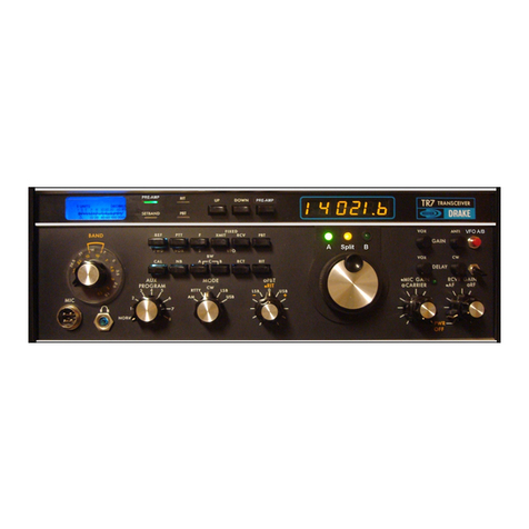
DRAKE ML-2 User manual


STANDARD
WARRANTY
R.
Le
DRAKE
COMPANY
warrants
each
new
radio
product
manufactured
by
it
to
be
free
from
defective
material
and
workmanship
and
agrees
to
remedy
any
such
defect
or
to
furnish
a
new
part
in
exchange
for
any
part
of
any
unit
of
its
manufacture
which
under
normal
installation,
use,
and
service
discloses
such
defect,
provided
the
unit
is
de-
livered
by
the
owner
to us
or
to
our
authorized
radio
dealer
or
wholesaler
from
whom
purchased,
intact,
for our
examination,
with
all
transportation
charges
prepaid
to
our
factory,
within
ninety
days
from
the
date
of
sale
to
original
purchaser
and
provided
that
such
examination
discloses
in
our
judgement
that
it
is
thus
defective.
Should
a
malfunction
be
suspected,
write
in
detail
to
our
Service
Department
for
suggestions
concerning
the
operation,
repair
or
return
of
your
unit
if
it
should
prove
necessarye
This
warranty
does
not
extend
to
any
of
our
radio
products
which
have
been
subjected
to
misuse,
neglect,
accident,
incorrect
wiring
not
our
own,
improper
installation,
or
to
use
in
violation
of
instructions
furnished
by
us,
nor
extend
to
units
which
have been
repaired
or
altered
outside
our
factory,
nor
in
cases
where
the
serial
number
thereof
has
been
removed,
defaced
or
changed,
nor
to
units
used
with
accessories
not
manufactured
or
recommended
by
us.
Any
part
of
a
unit
approved
for
remedy
or
exchange
hereunder
will
be
remedied
or
exchanged
by
the
authorized
radio
dealer
or
wholesaler
without
charge
to
the
owner.
This
warranty
is
in
lieu
of
all
other
warranties
expressed
or
implied
and
no
representative
or
person
is
authorized
to
assume
for
us
any
other
liability
in
connection
with
the
sale
of
our
radio
products.
The
Re
Le
DRAKE
COMPANY
reserves
the
right
to
make
any
improvements
to
its
products
which
it
may
deem
desirable
without
obligating
itself
to
install
such
improvements
in
its
previously
manufactured
products.
R.
Le
DRAKE
COMPANY
MIAMISBURG,
OHIO
45342
@

ML=2
CORRECTIONS
&
PART
CHANGES
In
some
ML=2's
the
following
parts
have
been
changed
as
noted
below,
In
each
case
these
parts
are
electrically
interchangeable,
2S8C
460
28C458
28C741
181555
Diode
2007
or
207
"
Diode
SRIEM1
Diode
SRIEM8
changed
to
28C838
28C
945
280319
18953
RD-7A-M
Fe14A
F-14D
ML-2
TRANSMIT.
&
RECEIVE
CRYSTALS
Crystals
for
your
ML-2
are
available
from
the
R. L.
Drake
Company
at
a
cost
of
$5.00
per
crystal.
Prior
authorization
must
be
obtained
from
the
R.
L.
Drake
Company
before
returning
crystals
for
any
reason.
Servial
hte
-
10
932
R,
L,
Drake
Company
September
21,
1971
orca


ML-2
MARKER
LUXURY
TRANSCEIVER
PAGE
1.
GENERAL
DESCRIPTION
...e..seeeee
seseoesesees
1
FEATURES.....
PEPE
NNNODeE
Qa
oO
3
g
o
~
YN
Hee
&
De
e
Q
©
&
<
o
5
2.
INSTALLATION.....
bbe
cece
eee
ee
cree cess
erescesees
O
UNPACKING
.......--
outeees
LOCATION
.cscecccccccccseecsccsere
NNN
NVYNYD
NOOhwWONne
VERTICAL
ANTENNAS........-
see
POWER
REQUIREMENTS
...ssseeceeeoeees
SPEAKER
AND
HEADPHONE
REQUIREMENTS
.
see
MICROPHONE
REQUIREMENTS
.+.sssssesesecsseceusesecs
w
CONTROL
FUNCTIONS
.........
teeeee
avec
eeceee
5
FRONT
PANEL
CONTROLS
..ccscecccscccccecccesreereres
On-Off
Switch
..
Volume......
Squelch.....
Re ee
OwWWWwWw
bodPE
INTERNAL
CONTROLS
....-ssecccecccccrcoccecesiovese
Deviation
Controls
......eeeeeeee
Transmitter
Frequency
Adjustment
...
Receiver
Frequency
Adjustment
....
S-Meter
Sensitivity
Adjustment
........
.
Relative
RF
Output
Meter
Adjustment
......
NNNNNN
arkrwondre
Ce
eeeeeerone
coccenee
WWW
ww
oo
>
CRYSTAL
ORDERING
INFORMATION.....-.e0002
7
5.
TROUBLE
SHOOTING.
cccccsvccccersccevcscecseceee
B
6.
SCHEMATIC
FOR
ML-2......
eee
eeecceeee
ee
eeeee
Fold
Out


1.1
1.2
1.2
vl
GENERAL
FEATURES
DESCRIPTION
The
ML-2
is
a
2
meter
VHF
-
FM
Transceiver
with
a
capacity
for
12
channels
and
will
operate
from
either
120
VAC
50
-
60
Hz
or
13.5
VDC.
SPECIFICATIONS.
GENERAL
Frequency
Coverage:
Number
of
Channels:
144
-
148
MHz
Completely
transistorized
with
a
6360
PA
tube.
12
channels,
3
supplied.
Channel
1
Channel
2
Channel
3
Receive:
146.94
MHz
Sreteceas=
146.76
MHz
Transmit:
146.34
MHz
ARS
SSeS
146.34
MHz
Simplex:
—if|
----------
146.94
MHz
=|
----------
Modulation:
Frequency
Modulation
Transmitter
Control:
Power
Drain:
Push-to-talk
A.C,
|
D.C.
“Receive:
6
watts
0.5
amps
Transmit:
50
watts
4.0
amps
Power
Source:
A.C.
120
Volts,
50
-
60
Hz.
D.C.
13.5
Volts,
+
10%
Dimensions;
Weight:
Accessories
Supplied:
7-7/8"
W
x
2-3/4"
H
x
10-1/4"
D
8-1/4
pounds.
-Antenna;
Dynamic
Microphone,
Antenna
Connector
Plug,
AC/DC
Power
Cord,
Speaker
Plug,
Mobile
Mounting
Bracket.
Page
lL.

1.2.2
1.2.3
RECEIVER
Receiver
Circuit:
ist
1.F.
Frequency:
2nd
I.F.
Frequency:
Antenna
Input
Impedance:
Sensitivity:
Spurious
Sensitivity:
Audio
Output:
TRANSMITTER
RF
Output
Power:
Frequency
Deviation:
Frequency
Stability:
Spurious
Radiation:
Completely
transistorized
crystal
controlled
double
conversion
superheterodyne
.
10.7
MHz
455
kHz
50
to
75
ohms
0.5
microvolt
or
less
for
20
dB
quieting.
1
microvolt
or
less
(30
dB
S
+
N/N
ratio
at
10
kHz
deviation
with
1
kHz
modulation.
Greater
than
-
60
dB
0.5
watt
at
10%
or
less
distortion
10
watts
conservative
Adjustable
to
15
kHz
maximum.
Factory
set
to
$
kHz
+
.001%
or
less.
Greater
than
-
80
dB
below
carrier.
Page
2.
0

2.
INSTALLATION
2.4
UNPACKING
@
Carefully
remove
the
Marker
Luxury
Transceiver
from
its
carton
and
examine
it
closely
for
signs
of
shipping
damage.
Should
any
be
apparent,
notify
the
delivering
carrier
immediately
stating
the
full
extent
of
the
damage.
Fill
Out
and mail
the
enclosed
registration
card
so
your
warranty
will
be
effec-
tive.
Save
the
packing
material.
You
may
need
it
later
for
reshipment
or
storage.
Inspect
the
packing
material
closely
before
putting
it
away
to
be
sure
you
have
not
overlooked
the
accessories
packed
with
the
unit.
2.2
LOCATION
_
In
general,
the
location
of
the
Marker
Luxury
is
not
critical.
However,
care
should
be
taken
to
insure
that
space
is
provided
around
the
unit
to
allow
adequate
air
circulation.
Extremely
hot
locations,
such
as
near
radiators
or
heating
units,
should
be
avoided.
DO
NOT
cover
the
top
of
the
unit
with
books,
papers
or
pieces
of
equipment
or
overheating
may
result.
2.3
ANTENNA
REQUIREMENTS
The
Marker
Luxury
Transceiver
is
designed
for
use
with
antennas
resonant
~
on the
operating
frequency
and
having
an
impedance
of
50
ohms.
The
e@
antenna
we
supply
must
be
adjusted
to
the
operating
frequency.
Tools
and
a
chart
are
supplied
for
this
adjustment.
The
antenna
can
be
adjusted
most
accurately
with
a
Drake
WV-4
Wattmeter
in
the
transmission
line.
With
the
WV-4
Wattmeter
in
the
line,
adjust
the
length
of
the
antenna
for
minimum
reverse
power
reading.
2.4
VERTICAL
ANTENNAS
Vertical
antennas
without
their
ground
planes should
not
be
used
with
the
ML-2.
Omission
of
the
ground
plane
causes
excessive
RF
ground
current
on
the
ML~2
case
resulting
in
RF
feedback
and
reports
of
hum
on
the
ML-2
transmitted
signal.
2.5
POWER
REQUIREMENTS
The
Marker
Luxury
Transceiver
is
factory
wired
for
use
with
120
volts
50
-
60
Hz
and
13.5
volts
DC.
For
use
on
120
volts,
insert
the
power
connector
with
the
line
cord
attached,
into
the
power
plug
on
the
rear
of
the
transceiver.
For
use
with
13.5
volts
DC,
insert
the
power
connector
with
the
red
and
black
wires
attached,
into the
power
plug
on
the
rear
of
the
transceiver.
The
red
wire
is
the
positive
lead
and
the
black
wire
negative.
The
fuse
in
the
positive
lead
has
a
value
of
6
amperes.
The
120
volt
fuse
has
a
value
of
2
amperes.
Page
3.

2.6
2.7
SPEAKER
AND
HEADPHONE
REQUIREMENTS
The
Marker
Luxury
Transceiver
has
a
built-in
speaker.
An
external
8
ohm
headphone.
or
speaker
may
be
plugged
into
the
miniature
phone
jack
on
the
rear
of
the
transceiver
chassis
next
to
the
R.F.
output
connector.
Plugging
an
external
speaker
or
headphone
into
this
jack
turns
off
the
built-in
speaker.
MICROPHONE
REQUIREMENTS
A
500
ohm
dynamic
microphone
with
a
push-to-talk
switch
is
supplied
with
the
Marker
Luxury
Transceiver.
A
carbon
microphone
may
be
used
with
the
transceiver
and
connection
to
the
microphone
plug
is
shown
in
the
schematic.
Page
4.

3.1
3.1.1
3.1.2
3.1.3
3.1.4
3.2
3.2.1
3.2.2
3.2
-3
CONTROL
FUNCTIONS
FRONT
PANEL
CONTROLS
ON-OFF
SWITCH
The
ON-OFF
switch
is
a
toggle
switch
in
the
left
bottom
of
the
front
panel
and
turns
the
transceiver
on
when
the
switch
lever
is
in
the
up
position.
VOLUME
The
AUDIO
GAIN
control
is
the
inner
knob
of
the
concentric
controls
at
the
left
top
of
the front
panel.
Clockwise
rotation
of
this
control
increases
audio
gain.
SQUELCH
The
SQUELCH
control
is
the
outer
knob
of
the
left
top
concentric
front
panel
controls.
Clockwise
rotation
increases
the
signal
level
required
to
defeat
the
squelch
circuit
and
allow
reception.
CHANNEL
SELECTOR
The
knob
in
the
center
of
the
front
panel
selects
one
of
twelve
possible
transmit
and
receive
crystal
pairs.
INTERNAL
CONTROLS
DEVIATION
CONTROL
With
the
cover
removed
and
front
panel
facing
you,
the
transmitter
circuit
board
is
visible
looking
into
the top
of
the
transceiver.
The
final
amplifier
tube
and
relay
are
also
exposed.
The
deviation
control
is
the
trimmer
resistor
at
the
right
rear
of
the
transmitter
circuit
board
.
This
control
is
set
by
ourselves
to
5
kHz
deviation.
Greater
deviation
than
this
can
be
obtained
by
counter-clockwise
rotation
of
this
control.
.Use
an
insulated
screwdriver
for
this
adjustment.
Accidental
connection
between
the
deviation
control
and
ground
will
destroy
IC
201.
TRANSMITTER
FREQUENCY
ADJUSTMENT
With
the
front
panel
facing
you
and
looking
into
the
top
of
the
transceiver,
the
transmitter
crystals
correspond
to
the
channel
numbers
and
are
numbered
right
to
left,
1
through
12.
There
are
two
banks
of
trimmer
capacitors
for
frequency
adjustment.
The
row
closest
to
the
front
panel
adjusts
even
num-
bered
crystals
right
to
left,
2
through
12.
The
row
next
to
the
sockets
adjust
odd
numbered
crystals
right
to
left,
1
through
11.
RECEIVER
FREQUENCY
ADJUSTMENT
With
the
front
panel
facing
you
and
looking
into
the
bottom
of
the
transceiver,
the
receiver
crystals
correspond
to
the
channel
numbers
and
are
numbered
right
to
left,
1
through
12.
There
are
two
banks
of
trimmer
inductors
for
fre-
Page
5.

3.2
3.2
“4
5
quency
adjustment.
The
row
closest
to
the
front
panel
adjusts
odd
numbered
crystals
right
to
left,
1
through
11.
The
row
next
to
the
crystal
sockets
adjust
even
numbered
crystals
right
to
left,
2
through
12.
The
slugs
are
anchored
with
wax.
Before
adjusting
the
slugs,
carefully
melt
the
wax
out
of
the
coil.
The
discriminator
output
for
setting
the
receiver
frequency
is
available
at
a
terminal
lug
on
the
receiver
circuit
board.
With
the
front
panel
facing
you
and
the
ML-2
upside
down,
the
discriminator
terminal
is
the
far
right
lug
on the
circuit
board
edge
closest
to
the
front
panel.
This
lug
has
nothing
connected
to
it.
Ground
for
a
voltmeter
connected
to
this
lug
is
most
convenient
at
the
heat
sink
of
the
audio
output
transistors
near
the
discriminator
terminal.
Note
that
all
circuit
board
grounds
are
NOT
connected
to
the
ML-2
chassis.
S-MEJER
SENSITIVITY
ADJUSTMENT
The
S-METER
response
sensitivity
is
determined
by
the
trim
pot
at
the
right
rear
of
the
receiver
circuit
board.
The
receiver
board
is
the
bottom
front
board
in
the
transceiver.
RELATIVE
RF_
OUTPUT
METER
ADJUSTMENT
The
RELATIVE
RF
OUTPUT
METER
sensitivity
is
determined
by
the
trim pot
at
the
right
rear
of
the
power
supply
board.
The
power
supply
board
is
the
bottom
rear
board
in
the
transceiver.
Page
6.

CRYSTAL
ORDERING
INFORMATION
Accessory
channel
crystals
may
be
ordered
from
the
R.
L.
Drake
Company.
To
order,
specify
the
desired receive
and
transmitting
frequency.
If
you
desire
to
order
crystals
from
another
source,
the
following
infor-
mation should
accompany
your
order.
TRANSMIT
CRYSTALS:
Fundamental
mode
parallel
resonant
with
30
pF
load
capacity
in
HC-25/U
holder.
Divide
transmit
frequency
by
12 to
obtain
crystal
frequency.
RECEIVE
CRYSTALS:
Overtone
mode
series
resonant
in
HC-25/U
holder.
Subtract
receive
frequency
by
10.694
MHz
and
divide
by
3
to
obtain
crystal
frequency.
Page
7.
-
ae

TROUBLE
SHOOTING
_
Careful
consideration
has
been
given
to
the
design
and
testing
of
the
ML-2
to
keeping
maintenance
problems
to
a
minimum.
If
you
experience
difficulty,
we
recommend
that
you
return
the
unit
to
your
Drake
dealer
or
write
direct
to
our
Customer
Service
Department
describing
your
problem
in
detail.
DO
NOT
RETURN
EQUIPMENT
TO
THE
FACTORY
WITHOUT
PRIOR
AUTHORIZATION.
k
|
Page
8.
ey

MUL-2
ELECTRICAL
PARTS
e
A.
POWER
SUPPLY.
R301
Resistor
R302
Resistor
R303
Resistor
R304
Resistor
R305
Resistor
R306,307
Resistors
R308
Resistor
C301
Capacitor
302
Capacitor
C303,304,310
Capacitors
C305
Capacitor
C306,307
Capacitors
308,309
Capacitors
C311,312,313
Capacitors
C314
Capacitor
Q301,302
,303
Transistors
Q304
Transistor
D301,302
,306
Diodes
D303
,304
Diodes
D305
Diode
PL301
Pilot
Lamp
8301
Switch
T301
Transformer
J301
Connector,
Plug
P301
Connector,
Socket
P302
Connector,
Socket
F301
Fuse
F302
Fuse
Page
9.
300
-10
5
1K
330
470
470
1000
uf
100
uf
47
uf
-047
uf
-005
/
.01
60
uf
-001
uf
-01
uf
2
SB
337
2
8C
460
SEIEM
1
SEIEM
8
MZ207
18V
3w
3w
3w
WW
1/aw
1/faw
1/aw
1/2
w
25
V
Electrolytic
16
V
Electrolytic
16
V
Electrolytic
400
V
Oil
500
V
Ceramic
160
V
Electrolytic
50
V
Ceramic
500
V
Ceramic
AC
Power
DPST
Power
12
P
Power
12
PDC
12
PAC
2
amp
6
amp
—_—

ML-2
ELECTRICAL
PARTS
B.
TRANSMITTER
R201,205,207,208,216,
219,222,228
*
R225
R202
,215
R203
R204
R206
R210
R213,214,220,223
,227
R217
R218
R221,224
R226
R231
R209
R211
R229,212
R230
R232
VR201,
202
C202
,219,237,250,260,261,262,
263,252,
253,254,255
204,212,210
C213
,223,225,230,235,236,238,
239,242
,231,256,257
C214,215
C216
,217
C218
220,233,241
C221,228
C222
C224
C226
,229
C227
C232
,249
C234
C243
,244
C257
258
C259
C245
,246
Resistors
Resistor
Resistors
Resistor
Resistor
Resistor
Resistor
Resistors
Resistor
Resistor
Resistors
Resistor
Resistor
Resistor
Resistor
Resistors
Resistor
Resistor
Resistors
Capacitors
Capacitors
Capacitors
Capacitors
Capacitors
Capacitor
Capacitors
Capacitors
Capacitor
Capacitor
Capacitors
Capacitor
Capacitors
Capacitor
Capacitors
Capacitor
Capacitor
Capacitor
Capacitors
Page
10.
1K
Ohms
100
Ohms
47K
330
Ohms
100
K
or
220K
33K
3.3K
10K
82
K
4.7K
150
Ohms
10
Ohms
1.5K
470
Ohms
330
Ohms
10K
20K
12K
10
K
Variable
-01
W
Ceramic
.1
u
Ceramic
or
Mylar
-001
W
Ceramic
500
pf
Ceramic
200
pf
Ceramic
60
pf
Ceramic
5
pf
Ceramic
80
pf
Ceramic
300
pf
Ceramic
15
pf
Ceramic
2
pf
Ceramic
20
pf
Ceramic
1
pf
Ceramic
10
pf
Ceramic
.001
or
.005
W
Ceramic
7.5
pf
N750
33
pf
Ceramic
25
pf
Ceramic
50
pf
Ceramic
I

B.
_TRANSMITTER
C247
C248,C264
thru
275
C201,203,211
C205
,207,208
C206
C209
C240
VC201
thru
214
VG215
Q201,202,203
Q204
Q205
1201
D201
D202
D203
v201
F201
J201
CH201
1201
thru
205
1LC201
thru
209
ML-2
ELECTRICAL
PART
Capacitor
Capacitors
Capacitors
Capaciters
Capacitor
Capacitor
Capacitor
Capacitors
,
Var.
Capacitor,
Var.
Transistors
Transistor
Transistor
1c
Diode
Diode
Diode
Tube
L.P.
Filter
Jack,
Mic.
Choke,
Iron
80
mH
Choke
,
RF
Coil,
RF
Page
11.
Ss
100
pf
Ceramic
7
pf
Ceramic
«5
uf 10
V
Alum.
4.7
W
16V
Elect.
10W
33
W
100
W
50
pf
20
pf
x
2
280460
28C717
280741
1A1201
1N60
MZ207
$C20
6360
LPF
4-pin

ML-2
ELECTRICAL
PARTS
C.
RECEIVER
_
R101,
102,
116,115,133
R103,
126,130,150,158
R104,
105,
122,134,141,149
R106,
107,109,112,
114,
145
R108
111,
124,142,147,151,
154,159,
118,and
180
thru
191
R110,121
R113
R119,123,140
R125,143,160
R127,128,135,137,153
R129,136,144,155,161
R131
R132
R138,139
R148
R152,120,117,157
R156
R146
VR101
VR102
C101,102A
and
D,107,108,109,113,
110,133,134,171,142,172,135,256,
257,
111
©103,104,112,116,118
ci21
106,259
C105
C169
,120
C115,117,119,122,124,125,
129,130,127,
126,140,141,172,
149,128,158,143,150,166,167,164,
144,
C123
C135
C134,136,138,139,165
C145
,146
C147
,153,163
cl48
C258
Page
12,
Resistors
Resistors
Resistors
Resistors
Resistors
Resistors
Resistor
Resistors
Resistors
Resistors
Resistors
Resistor
Resistor
Resistor
Resistor
Resistors
Resistor
Resistor
Resistor,
Var.
Resistor,
Var.
Capacitors
Capacitors
Capacitor
Capacitors
Capacitor
Capacitors
Capacitors
Capacitor
Capacitor
Capacitors
Capacitors
Capacitors
Capacitor
Capacitor
100K
22K
4.7K
100
u
1Ku
330-u
620
u
33
K
470u
47K
10K
470K
220K
82K
10u
3.3K
1.5.K
50u
10K
x
2
10K
x
2
(
-001
1.0
pf
25
pt
25
pf
3.0
pf
2.0
pf
Olu
10
pf
200
pf
-04u
330
pf
100
pé
-005
u y
33
pf

ML-2
ELECTRICAL
PARTS
csi
152,156
C154
C155,159
C157
C161
Q101,103,105,106
Q102
Q108,109,107
Q110,111,112,113,114
Q104
Q115,116
1C101
D101,102,103,104,107,108,109,110
D105,
106
F101
x101
T101
T102
y101
SP101
Capacitor,
Var.
Capacitor,
Capacitor
Capacitor
Capacitor
Capacitors
Capacitor
Capacitors
Capacitor
Capacitor
Transistors
Transistor
Transistors
Transistors
Transistor
Transistors
Ic.
Diode
Diode
Filter
Crystal
Transformer
Transformer
Jack,
Speaker
Speaker
Page
13.
50
pf
500
pf
47u
Su
150
pf
4.7u
1.0u
-lu
10u
47
u
28K19/33
3SK22
28C460
28C458
280717
2SB77
1A1201
1N60
181555
or
IS953
455
kHz
10.245
MHz
10K:
2
K
input
400
ohm
:
8
ohm
output
8
ohm

‘II
pue
[
z0F
x0,e{NZey
-
A
uoTq00g
*pesn
JON
-
III
wotqzo0ag
‘Zoe
[Npou
spsez
yndyno
‘god
wotqeTAep
nazy3
AI
Aq
pey
e8vys
xoTZTYdwy
-
T]
uoTz00g
‘II
Jo
yndut
07
uey,
*30d
uotqetAep
03
sa08
AI
JO
andqno
‘]T
uotR0ag
hq
poy
e8vzs
zoTZT[dwy
-
AT
uotT}oag
‘AI
WotTQ09g
BuTpeey
zeTJITTdwe
ouoydozoT
-
J
uoTq0eg
(10z
DI)
2039
Tusuezy
*peq.e[nSez
Jou
AT
uotq0es$
‘III
pue
II
‘I
suotq0eg
sz0z
a0jeTn8ex
OB3eITOA
-
\
uoTR0eg
AOIWITT
-
AI
uotTq0eg
“pus
qUOrZ
ABATODeI
IOJ
xrTZTTdwe
NAV
-
III
uotq0eg
“AI
WOTQ0eg
Suratap
z9TzTTdwy
-
[IT
uotz0eg
‘OL
UT
III
pue
IT
suotz00g
pue
(6010)
due
szejzem
8utatap
AOMOTTLOJ
19}7]TWY
-
J
uotqjoeg
(LOTOI)
reATEDEy
NOILONAA
9
1
W-2
Table of contents
Other DRAKE Transceiver manuals