Draper BUNKER 08242 User manual
Stock No.
08242
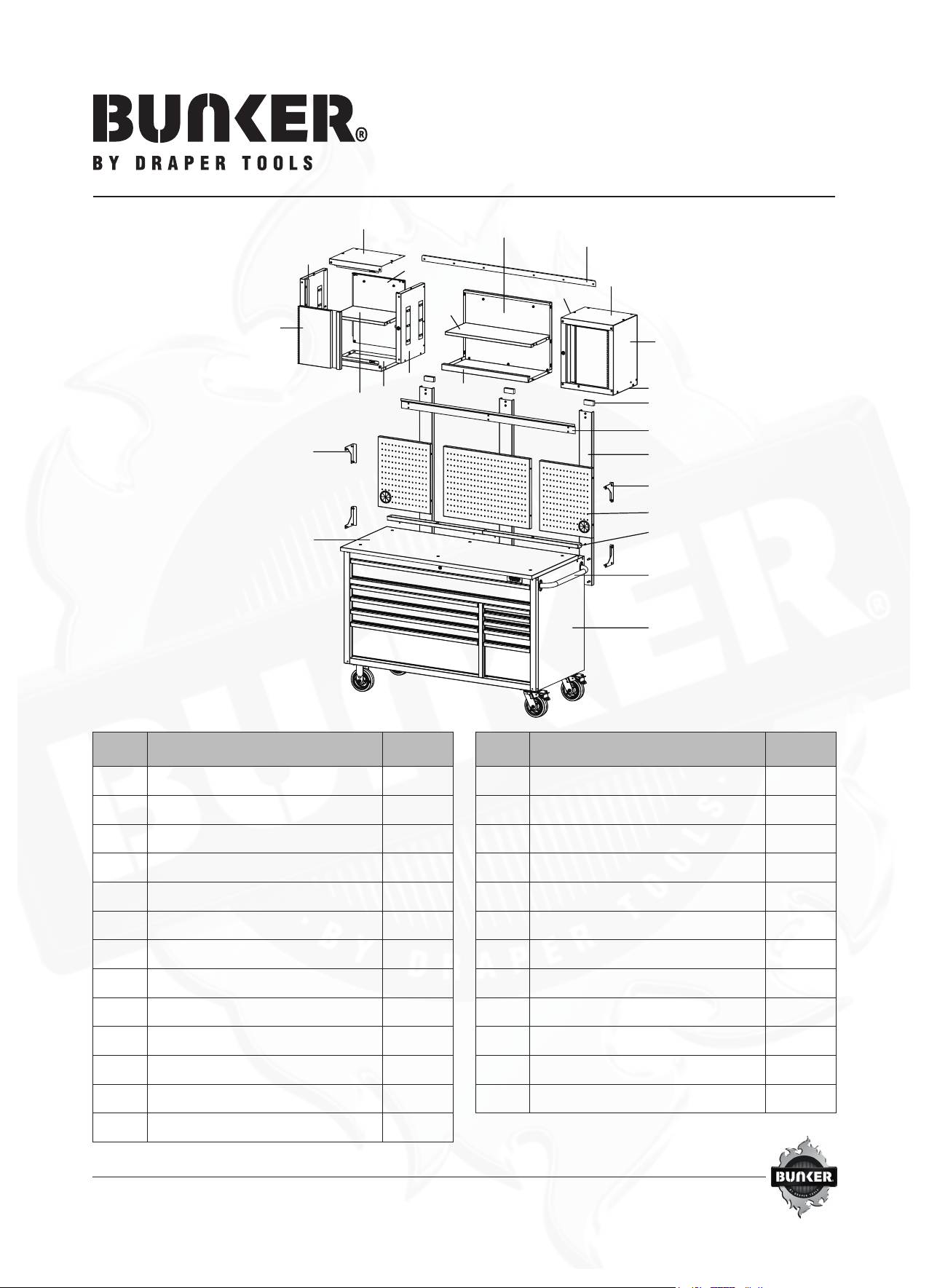
56” RollerWorkstationwith
Workbench, 10Drawer
PACKAGE CONTENTS
NOTE: The keys are inside top drawer.
K
X
A
B
G
I
H
E
C
J
R
T
P
O
NV
Q
Y
S
L
F
U
W
D
M
Part Description Quantity
A Cabinet handle 1
B Pegboard 3
C Mounting bracket 1
D Connecting brace 1
E Backwall 3
F L-shaped bracket (left) 2
G L-shaped bracket (right) 2
H EVA sticker 3
I Storage tray 2
J Back panel 1
K Shelf 1
L Bottom panel 1
M Door 2
Part Description Quantity
N Shelf (wall cabinet) 2
O Back panel (wall cabinet) 2
P Left side panel (left wall cabinet) 1
Q Right side panel (left wall cabinet) 1
R Left side panel (right wall cabinet) 1
S Right side panel (right wall cabinet) 1
T Top panel (left wall cabinet) 1
U Top panel (right wall cabinet) 1
V Bottom panel (left wall cabinet) 1
W Bottom panel (right wall cabinet) 1
X Cabinet 1
Y Rubber wood top 1

ASSEMBLY
To make assembly easier we recommend having two persons aid one another in assembly.
NOTE: The holes in the top cabinet are
tapped and do not require nuts.
NOTE: Side panels and back panel tabs (anges) must
be positioned on inside of cabinet facing up.
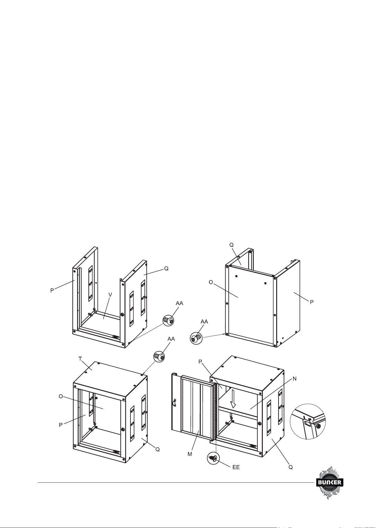
STEP 1: WALL CABINET ASSEMBLY
• For left side wall cabinet, attach side panels (P & Q) to
bottom panel (V) with M6 x 16mm bolts (AA) and tighten
with supplied hex key. Do not fully tighten. See Figure 1.1
• Insert back panel (O) inside the two side panels
(P & Q) and bottom (V). Align and insert M6 x 16mm bolts
(AA) into holes and tighten with supplied hex key. See
Figure 1.2
• Place top panel (T) over sides (P & Q) and back (O). Align
holes on top (T), sides (P & Q) and back (O) then tighten
with M6 x 16mm bolts (AA) and supplied hex key. Do not
fully tighten. See Figure 1.3
• Square up cabinet on a level surface and fully tighten all
M6 x 16mm bolts (AA) with supplied hex key.
• Align the holes on the hinge of the door (M) to the holes
on left side panel (P) then tighten with at head tapping
screws (EE) and screwdriver (not included). Ensure
the door is squared and ush with the cabinet before
tightening the screws. See Figure 1.4
• With the door (M) open insert the shelf panel (N) into
cabinet. Determine the desired height of shelf (N) and
secure by inserting shelf edges into the tab anges on the
two side panels (P & Q). If anges appear tight, lightly pry
to loosen. The left side wall cabinet assembly is complete.
• Repeat this process for the right side wall cabinet using
side panels (R & S).

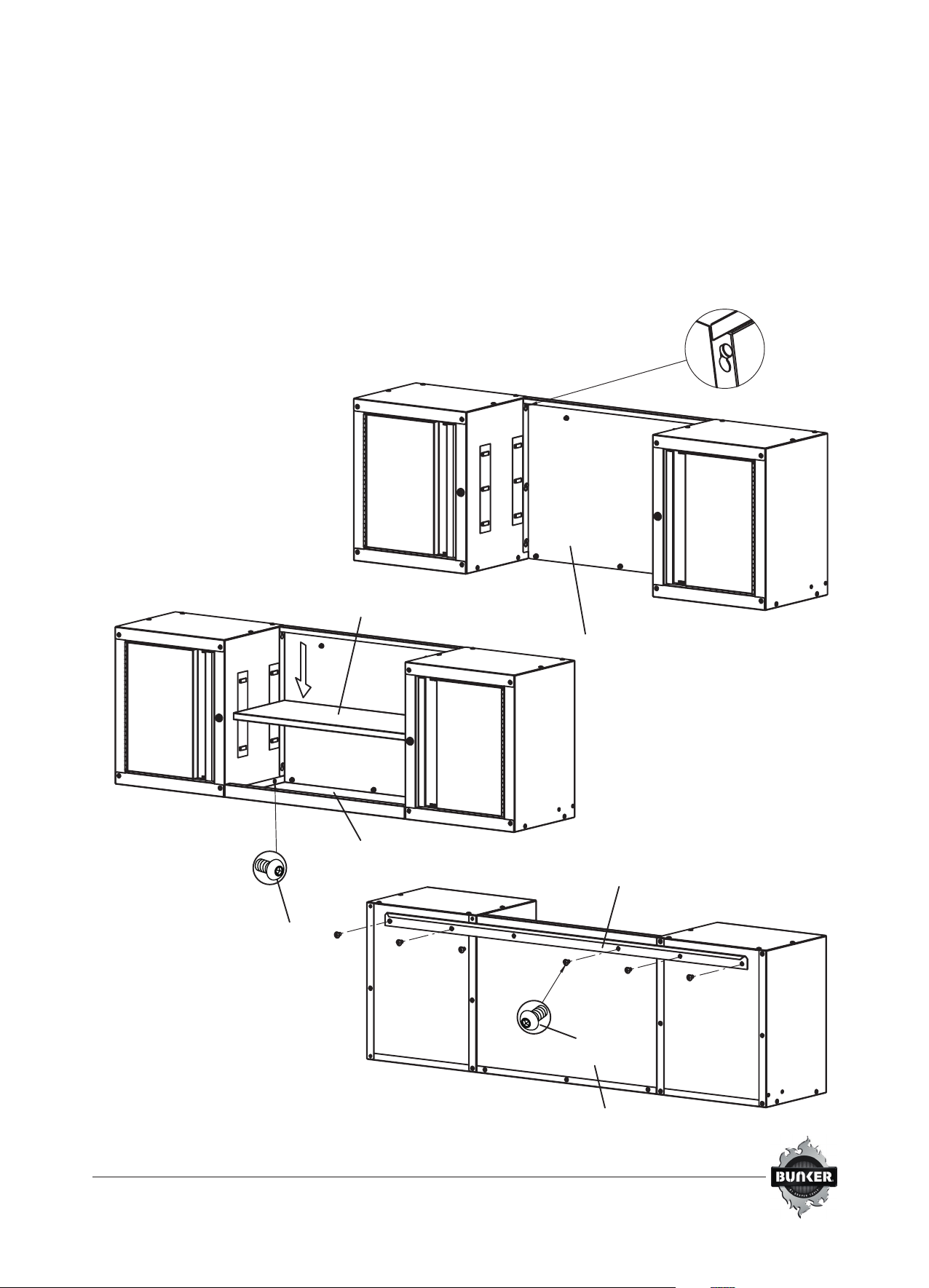
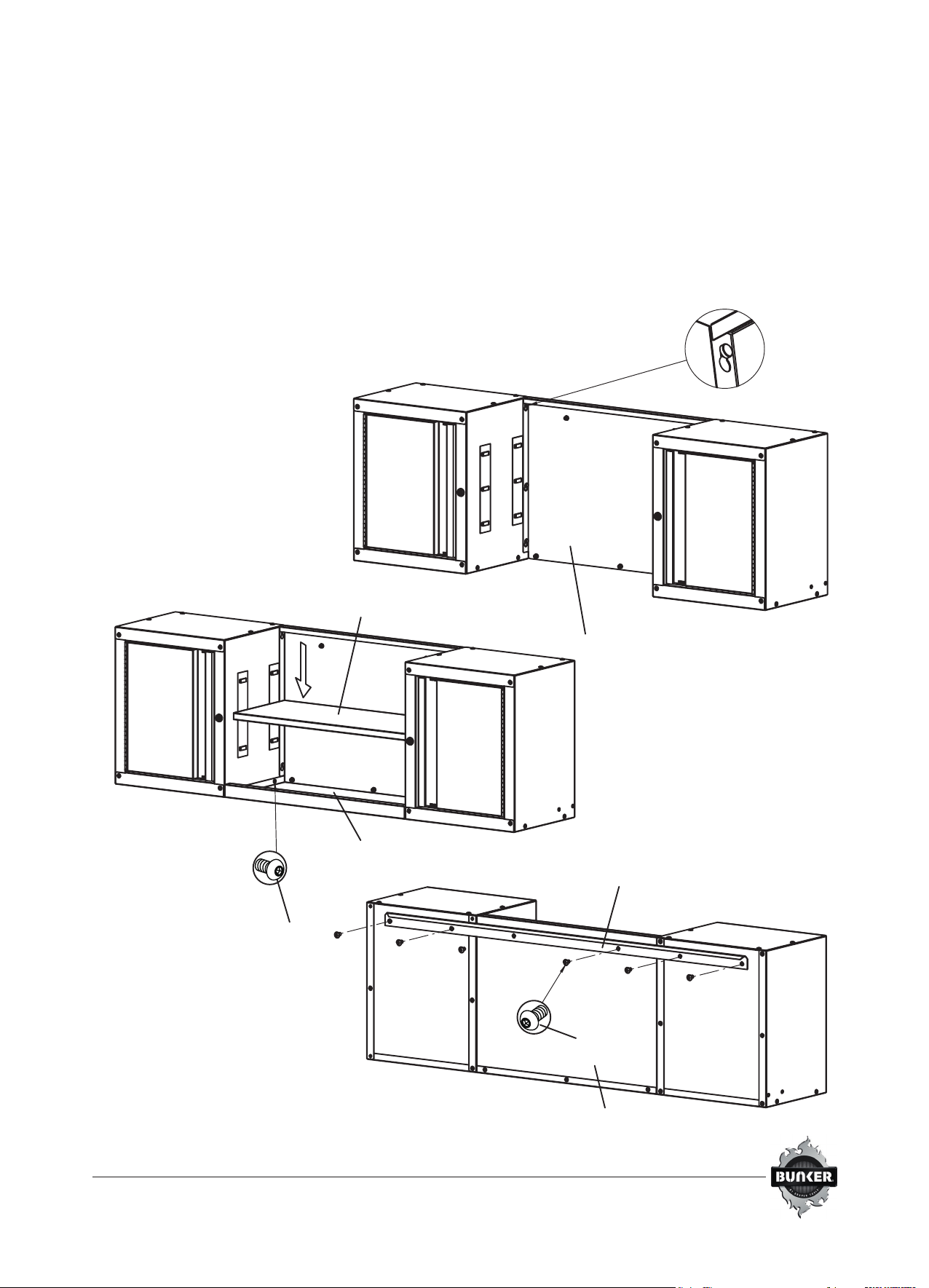
STEP 2: WALL CABINET SHELF ASSEMBLY
• Insert back panel (J) between the two wall cabinets and
secure the pins in the key holes. Ensure the top of the
back panel (J) is ush with the top of the cabinets. See
Figure 2.1
• Attach both wall cabinets to bottom panel (L) with
M6 x 16mm bolts (AA) and tighten with supplied hex key.
See Figure 2.2
• Determine the desired height of shelf (K) and secure by
inserting shelf edges into the tab anges on the right (or
left) panel of wall cabinets. If anges appear tight, lightly
pry to loosen.
• Align mounting bracket (C) holes to the back panel (J)
and wall cabinets, tighten with M6 x 16mm bolts (AA) and
supplied hex key, See Figure 2.3.
AA
AA
Figure 2.1
Figure 2.2
Figure 2.3
J
K
L
C
J

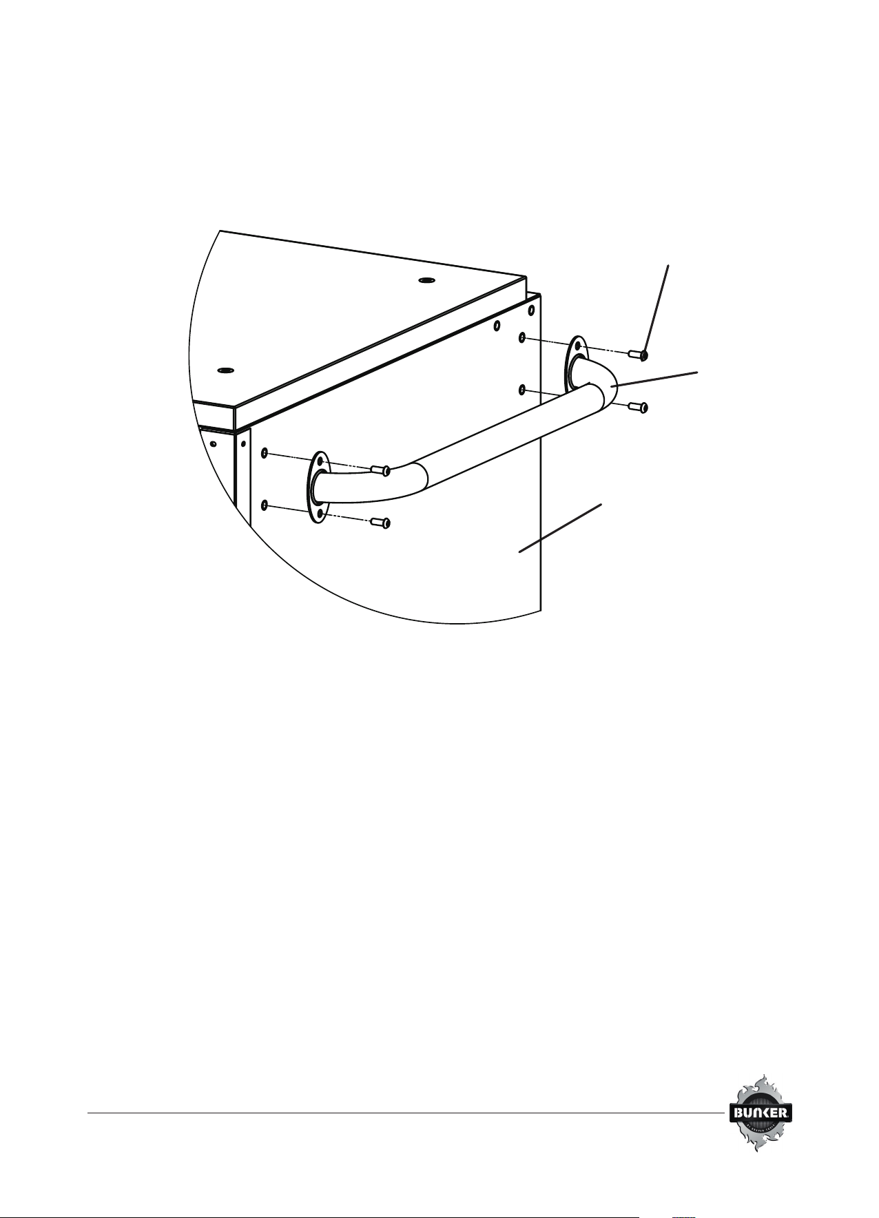
STEP 3: ATTACH CABINET HANDLE
NOTE: There are holes to mount handle on either side of cabinet, but only one handle comes with this cabinet.
•Position the cabinet handle (A) over the holes
on the cabinet (X).
•Attach with M6 x 16mm bolts (AA) and tighten
with supplied hex key.
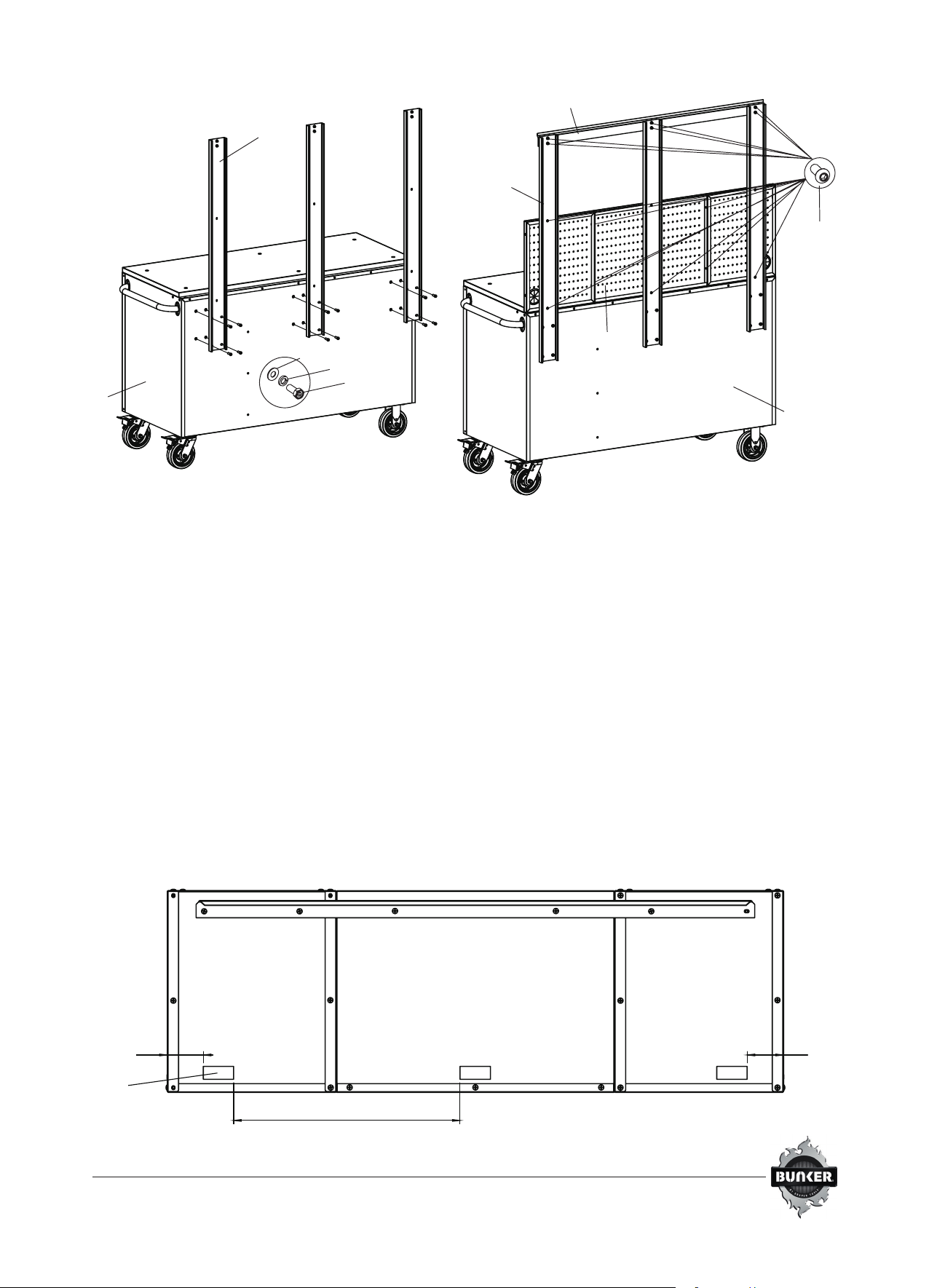
STEP 4: ATTACH PEGBOARD
•Position the backwalls (E) over the holes on
the cabinet (X).
•Secure with (4) M8 x 20mm bolts (BB), spring washers
(CC) and at washers (DD) per backwall (E) and tighten
with supplied hex key or 12mm wrench/socket (not
included). Do Not fully tighten bolts at this time.
See Figure 5.1
•Align the connecting brace (D) holes to
upper holes of backwall (E), tighten with (6)
M6 x 16mm bolts (AA) and supplied hex key. Do
Not fully tighten bolts at this time. See Figure 5.2
•Position each piece of pegboard (B) over the holes
on backwalls (E). Please note the grommet position
in the left and right pegboard panels in Figure 5.2
• Secure the pegboard panels (B) with (10) M6 x 16mm
bolts (AA) and tighten with supplied hex key.
•Once the pegboard panels (B) are secured
and squared, go back and tighten all hardware
in this step.
AA
X
A

CAUTION: Two people are recommended for this step
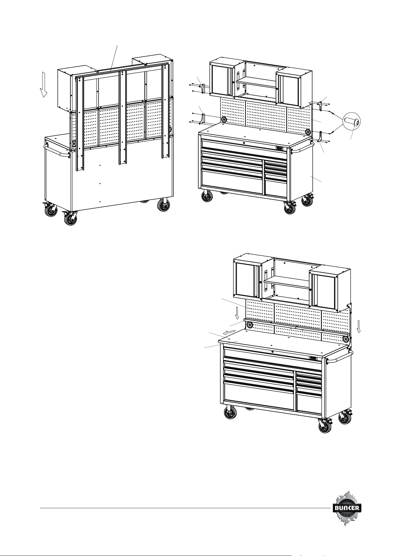
STEP 5: ATTACH WALL CABINET SYSTEM TO THE CABINET
• Peel o the paper back from the EVA stickers (H), then
attach in appropriate position toward bottom of wall
cabinets‘ back. See Figure 6.1.
•Hang wall cabinets onto connecting brace (D)
and ensure the cabinet mounting bracket (C)
is properly seated on the connecting brace (D).
See Figure 6.2.
•Secure the wall cabinets to the backwalls by
positioning the L-shaped brackets (F&G) over the
holes on the pegboard (B) and the wall cabinet.
See Figure 6.3.
•Attach with (3) M6 x 16mm bolts (AA) per L-shaped
brackets (F&G) and tighten with supplied hex key.
•Repeat this process for the other side of the pegboard
(B) to attach the wall cabinet to the cabinet (X).
NOTE: Wall cabinet may need to be hung on
connecting brace to determine the appropriate
position for EVA sticker.
Figure 6.1
H
3in3in
21in
X
BB
CC
DD
E
B
AA
X
E
D

STEP 6: ATTACH STORAGE TRAY
•Loosen M6 x 16mm bolts (AA) from rubber
wood top (Y) with supplied hex key.
• Gently pull the rubber wood top (Y) forward until 2”
of overhang on the front of the cabinet (X)
• Place the 2 storage trays (I) in the space created in
the back of the rubber wood top (Y) and pegboard
(B), and secure with (4) M6 x 16mm bolts (AA) and
supplied hex key.
•Tighten the 6 bolts in the rubber wood top (Y)
to secure in place with supplied hex key.
Be careful not to over tighten the bolts.
AA
Y
B
I
B
AA
X
Figure 6.2 Figure 6.3
C
F
F
G
G

drapertools.com
Draper Tools Limited, Hursley Road, Chandler’s Ford, Eastleigh, Hampshire. SO53 1YF UK.
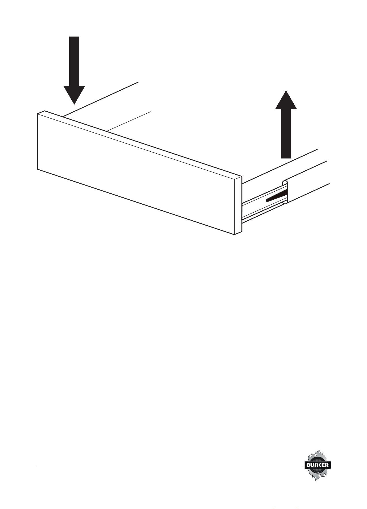
REMOVING AND REPLACING THE DRAWERS
• Pull the drawer completely out.
• Press down the left tab and lift up the right tab.
• Pull drawer o slides.
• To reinstall the drawer, realign with the internal drawer slide and push in until locked in place.
CASTOR MAINTENANCE
• Grease the castors annually using high-quality bearing grease.
CARE AND CLEANING
• Periodically the surfaces should be cleaned with a mild detergent and water. Grease and oil can
be removed with most standard cleaning uids. For safety, use a non-ammable cleaning uid.
• Auto wax will preserves the storage unit’s luster nish and protects against scratches.
Bestell-Nr.
08242
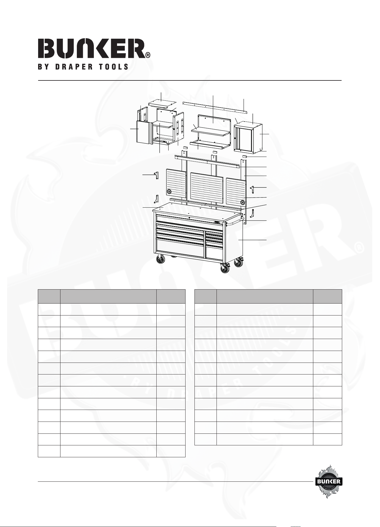
Werkstattwagen (142cm) mit
Werkbank, 10 Schubladen
PACKUNGSINHALT
HINWEIS: Die Schlüssel benden sich in der oberen Schublade
K
X
A
B
G
I
H
E
C
J
R
T
P
O
NV
Q
Y
S
L
F
U
W
D
M
Teil Beschreibung Menge
AGri 1
BLochwand 3
CMontagealterung 1
DVerbindungsstrebe 1
ERückwand 3
FL-Bügel (links) 2
GL-Bügel (rechts) 2
H EVA-Sticker 3
IAblagefach 2
JRückwand 1
KRegal 1
LUnterteil 1
MTür 2
Teil Beschreibung Menge
NRegal (Wandschrank) 2
ORückwand (Wandschrank) 2
PLinke Seitenwand (linker Wandschrank) 1
QRechte Seitenwand (linker Wandschrank) 1
RLinke Seitenwand (rechter Wandschrank) 1
SRechte Seitenwand (rechter Wandschrank) 1
tOberteil (linker Wandschrank) 1
UOberteil (rechter Wandschrank) 1
VUnterteil (linker Wandschrank) 1
W Unterteil (rechter Wandschrank) 1
XSchrank 1
YGummiholz-Arbeitsplatte 1

MONTAGE
Die Montage sollte von zwei Personen durchgeführt werden.
HINWEIS: Die Löcher im Oberschrank sind mit einem Gewinde
versehen und benötigen keine Muttern.
HINWEIS: Seitenwände und Rückwandlaschen (Flansche) müssen
an der Innenseite des Schranks nach oben gerichtet sein.
SCHRITT 1: MONTAGE DES WANSCHRANKS
• Bei linksseitigen Wandschränken die Seitenwände (P und Q) mit
M6x16mm Schrauben (AA) an der Bodenplatte (V) befestigen
und mit dem mitgelieferten Sechskantschlüssel festziehen. Nicht
vollständig festziehen. Siehe Abbildung 1.1
• Die Rückwand (O) in die beiden Seitenwände (P und Q) und
den Boden (V) einsetzen. Die M6x16-mm-Schrauben (AA)
ausrichten, in die Löcher einsetzen und mit dem mitgelieferten
Sechskantschlüssel festziehen. Siehe Abbildung 1.2
• Die Oberplatte (T) über die Seiten (P und Q) und die Rückwand (O)
legen. Die Löcher an der Oberplatte an den Seitenwänden (P und
Q) und der Rückwand (O) ausrichten und mit den M6x16-mm-
Schrauben (AA) und dem mitgelieferten Sechskantschlüssel
festziehen. Nicht vollständig festziehen. Siehe Abbildung 1.3
• Den Schrank auf einer ebenen Fläche ausrichten und
alle M6x16mm Schrauben (AA) mit dem mitgelieferten
Sechskantschlüssel festziehen.
• Die Löcher am Scharnier der Tür (M) auf die Löcher an der linken
Seitenwand (P) ausrichten und mit Flachkopfschrauben (EE)
und einem Schraubendreher (nicht im Lieferumfang enthalten)
festziehen. Sicherstellen, dass die Tür rechtwinklig und bündig am
Schrank ausgerichtet ist, bevor die Schrauben angezogen werden.
Siehe Abbildung 1.4
• Die Regalplatte (N) bei geöneter Tür (M) in den Schrank
einsetzen. Die gewünschte Höhe des Regals (N) bestimmen und
das Regal durch Einführen der Kanten des Regals in die Laschen
an den beiden Seitenteilen (P & Q) befestigen. Wenn die Flansche
fest zu sitzen scheinen, zum Lockern leicht anheben. Die Montage
des linken Wandschranks ist nun abgeschlossen.
• Diesen Vorgang für den rechten Oberschrank wiederholen.
Dazudie rechten Seitenwänden (R & S verwenden.
Abbildung 1.1 Abbildung 1.2
Abbildung 1.4
Abbildung 1.3
SCHRITT 2: EINBAU DER REGALE
• Die Rückwand (J) zwischen den beiden Wandschränken einsetzen
und die Stifte in den Schlüssellöchern sichern. Sicherstellen,
dass die Oberseite der Rückwand (J) bündig mit der Oberseite der
Schränke ausgerichtet ist. Siehe Abbildung 2.1
• Beide Wandschränke mit M6x16mm Schrauben (AA) an
der Bodenplatte (L) befestigen und mit dem mitgelieferten
Sechskantschlüssel festziehen. Siehe Abbildung 2.2
• Die gewünschte Höhe des Regals (K) bestimmen und das Regal
durch Einführen der Kanten des Regals in die Laschen an der
rechten (oder linken) Seitenplatte der Wandschränke befestigen.
Wenn die Flansche fest zu sitzen scheinen, zum Lockern leicht
anheben.
• Die Löcher der Montagehalterung (C) an der Rückwand (J)
und den Wandschränken ausrichten und mit den Schrauben
M6x16mm (AA) und dem mitgelieferten Sechskantschlüssel
festziehen, siehe Abbildung 2.3.
AA
AA
J
K
L
C
J
Abbildung 2.1
Abbildung 2.2
Abbildung 2.3
SCHRITT 3: BEFESTIGUNG DES SCHRANKGRIFFS
HINWEIS: An beiden Seiten des Schranks sind Löcher für die Montage von Grien vorhanden. Es ist jedoch nur ein Gri im
Lieferumfang enthalten.
• Den Schrankgri (A) über den Löchern am Schrank (X)
anordnen.
• Mit M6x16-mm-Schrauben (AA) befestigen und mit
dem mitgelieferten Sechskantschlüssel festziehen.
SCHRITT 4: BEFESTIGUNG DER LOCHWAND
• Die Rückwände (E) über den Löchern im Schrank (X) anordnen
• Die Rückwand (E) mit (4) Schrauben M8x20mm (BB),
Federscheiben (CC) und Unterlegscheiben (DD) sichern und mit
dem mitgelieferten Sechskantschlüssel oder einem 12-mm-
Schlüssel (nicht im Lieferumfang enthalten) festziehen.
Die Schrauben zu diesem Zeitpunkt noch nicht vollständig
anziehen. Siehe Abbildung 5.1
• Die Löcher der Verbindungsstrebe (D) an den oberen Löchern
der Rückwand (E) ausrichten und mit den 6 Schrauben
M6x16mm (AA) und dem mitgelieferten Sechskantschlüssel
festziehen. Die Schrauben zu diesem Zeitpunkt noch nicht
vollständig anziehen. Siehe Abbildung 5.2
• Jeden Teil der Lochwand (B) über den Löchern an den
Rückwänden (E) positionieren. Die Position der Tüllen in
der linken und rechten Lochwand in Abbildung 5.2 beachten.
• Die Lochwandplatten (B) mit (10) Schrauben M6x16mm
(AA) sichern und mit dem mitgelieferten Sechskantschlüssel
festziehen.
• Sobald die Lochwände (B) befestigt und ausgerichtet sind,
alle Teile in diesem Schritt wieder festziehen
AA
X
A

VORSICHT: Dieser Schritt sollte von zwei Personen durchgeführt werden.
SCHRITT 5: WANDSCHRANKSYSTEM AM SCHRANK BEFESTIGEN
• Die Papierrückseite von den EVA-Aufklebern (H) abziehen
und die Aufkleber in der entsprechenden Position an der
Unterseite der Rückwand der Wandschränke anbringen.
Siehe Abbildung 6.1
• Die Wandschränke in die Verbindungsstrebe (D) einhängen
und sicherstellen, dass die Schrankhalterung (C) richtig auf
der Verbindungsstrebe (D) sitzt. Siehe Abbildung 6.2
• Die Wandschränke an den Rückwänden befestige. Dazu
die L-förmigen Halterungen (F&G) über den Löchern auf
der Lochwand (B) und dem Wandschrank positionieren.
Siehe Abbildung 6.3
• Die L-förmigen Halterungen (F und G) mit 3 Schrauben
M6x16mm (AA) befestigen und mit dem mitgelieferten
Sechskantschlüssel festziehen.
• Diesen Vorgang für die andere Seite der Lochwand (B)
wiederholen, um den Wandschrank am Schrank (X)
zu befestigen.
HINWEIS: Der Wandschrank muss eventuell an der
Verbindungsstrebe aufgehängt werden, um die geeignete
Position für den EVA-Aufkleber zu bestimmen.
H
3in3in
21in
X
BB
CC
DD
E
B
AA
X
E
D
Abbildung 5.1 Abbildung 5.2
Abbildung 6.1

SCHRITT 6: ANBRINGEN DES
ABLAGEFACHS
• Die M6x16-mm-Schrauben (AA) mit dem mitgelieferten
Sechskantschlüssel von der Gummiholzplatte (Y)
entfernen.
• Die Gummiholzplatte (Y) vorsichtig nach vorn ziehen, bis
ein Überstand von 2" an der Vorderseite des Gehäuses (X)
entsteht.
• Die 2 Ablagefächer (I) in den Raum einsetzen, der auf der
Rückseite der Gummiholzplatte (Y) und der Lochwand (B)
entstanden ist, und sie mit (4) M6x16-mm-Schrauben (AA)
und dem mitgelieferten Sechskantschlüssel befestigen.
• Die 6 Schrauben in der Gummiholzplatte (Y) mit dem
mitgelieferten Sechskantschlüssel festziehen.
Die Schrauben nicht zu fest anziehen.
AA
Y
B
I
B
AA
X
C
F
F
G
G
Abbildung 6.2 Abbildung 6.3
drapertools.com
Draper Tools Limited, Hursley Road, Chandler’s Ford, Eastleigh, Hampshire. SO53 1YF UK.
HERAUSNEHMEN UND EINSETZEN DER SCHUBLADEN
• Die Schublade vollständig herausziehen.
• Die linke Lasche nach unten drücken und die rechte Lasche anheben.
• Die Schublade von den Schienen ziehen.
• Die Schublade zum Wiedereinsetzen an der inneren Schubladenführung ausrichten und einschieben, bis sie einrastet.
INSTANDHALTUNG DER LAUFROLLEN
• Die Rollen jährlich mit hochwertigem Lagerfett schmieren.
PFLEGE UND REINIGUNG
• Die Oberächen in regelmäßigen Abständen mit einem milden Reinigungsmittel und Wasser reinigen. Fett und Öl können
mit den meisten handelsüblichen Reinigungsmitteln entfernt werden. Aus Sicherheitsgründen eine nicht brennbare
Reinigungsüssigkeit verwenden.
• Autowachs sorgt für eine glänzende Oberäche der Lagereinheit und schützt vor Kratzern.
(L)
(R)

N.º de pieza
08242
Estación de trabajo con
ruedas con banco de trabajo
56”, 10 cajones
CONTENIDO DEL PAQUETE
NOTA: Las llaves están dentro del cajón superior.
K
X
A
B
G
I
H
E
C
J
R
T
P
O
NV
Q
Y
S
L
F
U
W
D
M
Pieza Descripción Cantidad
A Asa del armario 1
B Tablero perforado 3
C Soporte de montaje 1
D Travesaño de unión 1
E Travesaño de pared 3
F Soporte en forma de L (izquierdo) 2
G Soporte en forma de L (derecho) 2
H Pegatina EVA 3
I Bandeja de almacenamiento 2
J Panel posterior 1
K Estante 1
L Panel inferior 1
M Puerta 2
Pieza Descripción Cantidad
N Estante (armario) 2
O Panel posterior (armario) 2
P Panel lateral izquierdo (armario izquierdo) 1
Q Panel lateral derecho (armario izquierdo) 1
R Panel lateral izquierdo (armario derecho) 1
S Panel lateral derecho (armario derecho) 1
T Panel superior (armario izquierdo) 1
U Panel superior (armario derecho) 1
V Panel inferior (armario izquierdo) 1
W Panel inferior (armario derecho) 1
X Armario 1
Y Encimera de madera de caucho 1
MONTAJE
Para facilitar el montaje, recomendamos la intervención de dos personas para ayudarse mutuamente en el montaje.
NOTA: Los agujeros de la encimera son de rosca
y no requieren tuercas.
NOTA: Los paneles laterales y las pestañas del panel
trasero (sujeciones) deben colocarse en el interior del
armario mirando hacia arriba.
PASO 1: MONTAJE DEL ARMARIO
• Para el armario del lado izquierdo, je los paneles laterales
(P y Q) al panel inferior (V) con los pernos M6x16mm (AA)
y apriete con la llave hexagonal suministrada. No apriete en
exceso. Ver Figura 1.1.
• Inserte el panel posterior (O) dentro de los dos paneles
laterales (P y Q) y el panel inferior (V). Alinee e inserte los
pernos M6x16mm (AA) en los agujeros y apriete con la llave
hexagonal suministrada. Ver Figura 1.2.
• Coloque el panel superior (T) sobre los laterales (P y Q) y el
panel posterior (O). Alinee los agujeros del panel superior (T),
los laterales (P y Q) y el panel posterior (O) y apriete con los
pernos M6x16mm (AA) y la llave hexagonal suministrada.
No apriete en exceso. Ver Figura 1.3.
• Coloque el armario en una supercie nivelada y apriete
completamente todos los pernos M6x16mm (AA) con la llave
hexagonal suministrada.
• Alinee los agujeros en la bisagra de la puerta (M) con los
agujeros del panel lateral izquierdo (P) y apriete con los
tornillos de cabeza plana (EE) y un destornillador (no incluido).
Asegúrese de que la puerta quede encuadrada y enrasada con
el armario antes de apretar los tornillos. Ver Figura 1.4.
• Con la puerta (M) abierta, introduzca el panel del estante (N)
en el armario. Determine la altura deseada del estante (N) y
fíjelo introduciendo los bordes del estante en las pestañas de
sujeción de los dos paneles laterales (P y Q). Si las sujeciones
parecen estar un poco ajustadas, haga una ligera palanca
para aojarlas. El montaje del armario de la izquierda ya está
completo.
• Repita este proceso para el armario de la derecha utilizando
los paneles laterales (R y S).
Figura 1.1
Figura 1.3 Figura 1.4
Figura 1.2
PASO 2: MONTAJE DEL ESTANTE DEL ARMARIO
• Introduzca el panel trasero (J) entre los dos armarios y je los
pasadores en los agujeros. Asegúrese de que la parte superior
del panel trasero (J) esté enrasada con la parte superior de
los armarios. Ver Figura 2.1.
• Fije ambos armarios al panel inferior (L) con los pernos
M6x16mm (AA) y apriete con la llave hexagonal
suministrada. Ver Figura 2.2.
• Determine la altura deseada del estante (K) y fíjelo insertando
los bordes del estante en las pestañas de sujeción del panel
derecho (o izquierdo) de los armarios. Si las sujeciones parecen
estar un poco ajustadas, haga una ligera palanca
para aojarlas.
• Alinee los agujeros del soporte de montaje (C) con el panel
trasero (J) y los armarios, apriete con los pernos M6x16mm
(AA) y la llave hexagonal suministrada. Ver Figura 2.3.
AA
AA
J
K
L
C
J
Figura 2.1
Figura 2.2
Figura 2.3

PASO 3: FIJACIÓN DEL ASA DEL ARMARIO
NOTA: Hay unos agujeros para montar el asa en cualquier lado del armario, pero el armario solo viene con un asa.
• Coloque el asa del armario (A) sobre los agujeros del
armario(X).
• Fije con los pernos M6x16mm (AA) y apriete con la llave
hexagonal suministrada.
PASO 4: FIJACIÓN DEL TABLERO PERFORADO
• Coloque los travesaños de pared (E) sobre los agujeros del
del armario (X)
• Fíjelos con 4 pernos M8x20mm (BB), arandelas de presión
(CC) y arandelas planas (DD) por cada travesaño (E) y apriete
con la llave hexagonal suministrada o con una llave de vaso/
inglesa de 12mm (no incluida). No apriete demasiado los
pernos de momento. Ver Figura 5.1.
• Alinee los agujeros del travesaño de unión (D) con los agujeros
superiores del travesaño de pared (E), apriete con 6pernos
M6x16mm (AA) y la llave hexagonal suministrada. No apriete
demasiado los pernos de momento. Ver Figura5.2.
• Coloque cada pieza de tablero perforado (B) sobre los agujeros
de los travesaños de pared (E). Tenga en cuenta la posición
de los ojales en los paneles perforados izquierdo y derecho.
• Fije los paneles perforados (B) con 10 pernos M6x16mm (AA)
y apriete con la llave hexagonal suministrada.
• Una vez que los paneles del tablero perforado (B) estén jados
y encuadrados, vuelva a apretar todos los tornillos y pernos
en este paso.
AA
X
A
PRECAUCIÓN: Se recomienda la intervención de dos personas en este paso
PASO 5: FIJACIÓN DEL SISTEMA DE ARMARIOS A LA ESTRUCTURA DEL ARMARIO
• Despegue el papel de las pegatinas de EVA (H) y fíjelas en
la posición adecuada en la parte trasera de los armarios.
VerFigura 6.1.
• Cuelgue los armarios en el travesaño de unión (D) y
compruebe que el soporte de montaje del armario (C) esté
correctamente asentado en el travesaño de unión (D).
VerFigura 6.2.
• Fije los armarios a los travesaños de pared colocando los
soportes en forma de L (F y G) sobre los oricios del tablero
perforado (B) y el armario. Ver Figura 6.3.
• Fije con 3 pernos M6x16mm (AA) por cada soporte en forma
de L (F y G) y apriete con la llave hexagonal suministrada.
• Repita este proceso para el otro lado del tablero perforado
(B) para jar el armario a la estructura del armario (X).
NOTA: Es posible que haya que colgar el armario en el
travesaño de unión para determinar la posición adecuada
de la pegatina.
H
3in3in
21in
X
BB
CC
DD
E
B
AA
X
E
D
Figura 5.1 Figura 5.2
Figura 6.1
PASO 6: FIJACIÓN DE LA BANDEJA DE
ALMACENAMIENTO
• Aoje los pernos M6x16mm (AA) de la encimera de
madera de caucho (Y) con la llave hexagonal suministrada.
• Tire suavemente de la encimera (Y) hacia delante hasta
que sobresalga 2" por delante del armario (X)
• Coloque las 2 bandejas de almacenamiento (I) en el
espacio creado detrás de la encimera (Y) y el tablero
perforado (B), y fíjelas con 4 pernos M6x16mm (AA)
y la llave hexagonal suministrada.
• Apriete los 6 pernos de la encimera (Y) para asegurarla
en su sitio con la llave hexagonal suministrada.
Procure no apretar demasiado los pernos.
AA
Y
B
I
B
AA
X
C
F
F
G
G
Figura 6.2 Figura 6.3
Table of contents
Languages:


