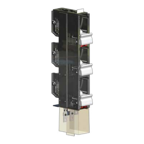
DRIESCHER ECOS-C User manual

B
ECOS-C
User manual
DRIESCHER
Medium voltage-
Compact switchgear
ECOS-C
• Indoor
• SF6-free
• Rated voltage 24 kV
STROM • SICHER • SCHALTEN

MV - Compact switchgear ECOS-C
B ECOS-C
Contents
1 INTRO UCTION 5
1.1 Copyright . . . . . . . . . . . . . . . . . . . . . . . . . . . . . . . . . . . . . . . . . . . . . . 5
1.2 Hazard signs . . . . . . . . . . . . . . . . . . . . . . . . . . . . . . . . . . . . . . . . . . . . 5
1.3 Guarantee and indemnification . . . . . . . . . . . . . . . . . . . . . . . . . . . . . . 6
1.4 Basis of this user manual . . . . . . . . . . . . . . . . . . . . . . . . . . . . . . . . . . 6
1.5 Associated documents . . . . . . . . . . . . . . . . . . . . . . . . . . . . . . . . . . . . 6
1.6 Quality Assurance . . . . . . . . . . . . . . . . . . . . . . . . . . . . . . . . . . . . . . . 6
1.7 Type testing . . . . . . . . . . . . . . . . . . . . . . . . . . . . . . . . . . . . . . . . . . . . 7
1.8 Manufacturing standards – conformity . . . . . . . . . . . . . . . . . . . . . . . . 7
2 SAFETY 8
2.1 General Safety Instructions . . . . . . . . . . . . . . . . . . . . . . . . . . . . . . . . 8
2.1.1 Use for the intended purpose
2.2 Operational safety instructions . . . . . . . . . . . . . . . . . . . . . . . . . . . . . . 9
2.2.1 The 5 safety rules
2.2.2 uties of the operating company
2.2.3 Qualification and requirements of personnel
2.2.4 Fire prevention requirements
3 TECHNICAL ESCRIPTION 11
3.1 Technical data of the switchgear . . . . . . . . . . . . . . . . . . . . . . . . . . . . 11
3.2 Technical data of the circuit breaker . . . . . . . . . . . . . . . . . . . . . . . . . . 12
3.3 Function and design . . . . . . . . . . . . . . . . . . . . . . . . . . . . . . . . . . . . . 13
3.3.1 Performance profile
3.3.2 esign features
3.3.3 Vacuum interrupter technology
3.3.4 esign of the switch unit
3.3.5 esign of the switch system
3.3.6 esign of the switchgear
3.3.7 Behaviour in the event of internal faults
3.3.8 Option - Motorised drive for the main spring
3.3.9 Option - igital protective relay
3.3.10 Option - Secondary cabinet
3.3.11 Option - Heating
3.3.12 Option - Measurement panel
3.3.13 Other options
3.4 imensions and Floor Recesses . . . . . . . . . . . . . . . . . . . . . . . . . . . . . 23
3.5 Schematic diagram . . . . . . . . . . . . . . . . . . . . . . . . . . . . . . . . . . . . . . . 26
2 / 52

Contents
4 TRANSPORT AN STORAGE 30
4.1 Handling instructions . . . . . . . . . . . . . . . . . . . . . . . . . . . . . . . . . . . . . . 30
4.2 Transport . . . . . . . . . . . . . . . . . . . . . . . . . . . . . . . . . . . . . . . . . . . . . . 31
4.3 Storage . . . . . . . . . . . . . . . . . . . . . . . . . . . . . . . . . . . . . . . . . . . . . . . . 32
5 ERECTION AN INSTALLATION 33
5.1 Safety instructions . . . . . . . . . . . . . . . . . . . . . . . . . . . . . . . . . . . . . . . . 33
5.2 Erection . . . . . . . . . . . . . . . . . . . . . . . . . . . . . . . . . . . . . . . . . . . . . . . 33
5.3 Installation . . . . . . . . . . . . . . . . . . . . . . . . . . . . . . . . . . . . . . . . . . . . . 33
5.4 Installation and earthing the cable connections . . . . . . . . . . . . . . . . . . 34
6 COMMISSIONING AN OPERATION 36
6.1 Safety instructions . . . . . . . . . . . . . . . . . . . . . . . . . . . . . . . . . . . . . . . . 36
6.2 Commissioning . . . . . . . . . . . . . . . . . . . . . . . . . . . . . . . . . . . . . . . . . . 36
6.3 Operation . . . . . . . . . . . . . . . . . . . . . . . . . . . . . . . . . . . . . . . . . . . . . . 37
6.4 Switching . . . . . . . . . . . . . . . . . . . . . . . . . . . . . . . . . . . . . . . . . . . . . . 38
6.5 Changing over the pre-selector switch . . . . . . . . . . . . . . . . . . . . . . . . . 38
6.6 Voltage display . . . . . . . . . . . . . . . . . . . . . . . . . . . . . . . . . . . . . . . . . . 38
6.7 Earthing the input or output cables . . . . . . . . . . . . . . . . . . . . . . . . . . . 39
6.8 Testing the cables . . . . . . . . . . . . . . . . . . . . . . . . . . . . . . . . . . . . . . . . 39
6.9 Insulating fluid level sight glass . . . . . . . . . . . . . . . . . . . . . . . . . . . . . . 40
6.10 Mechanical switching cycle counter . . . . . . . . . . . . . . . . . . . . . . . . . . . 40
7 REPAIR 41
7.1 Basis for repair . . . . . . . . . . . . . . . . . . . . . . . . . . . . . . . . . . . . . . . . . . 41
7.2 Concept . . . . . . . . . . . . . . . . . . . . . . . . . . . . . . . . . . . . . . . . . . . . . . 41
7.3 Visual check . . . . . . . . . . . . . . . . . . . . . . . . . . . . . . . . . . . . . . . . . . . 42
7.4 Inspection . . . . . . . . . . . . . . . . . . . . . . . . . . . . . . . . . . . . . . . . . . . . . 43
7.5 Maintenance . . . . . . . . . . . . . . . . . . . . . . . . . . . . . . . . . . . . . . . . . . . 43
7.6 Corrective maintenance / Upgrade . . . . . . . . . . . . . . . . . . . . . . . . . . . 44
7.7 End of working life . . . . . . . . . . . . . . . . . . . . . . . . . . . . . . . . . . . . . . . 45
MV - Compact switchgear ECOS-C
B ECOS-C
3 / 52

8 APPEN IX 46
8.1 Nameplate . . . . . . . . . . . . . . . . . . . . . . . . . . . . . . . . . . . . . . . . . . . . . 46
8.2 Accessories and spare parts . . . . . . . . . . . . . . . . . . . . . . . . . . . . . . . . 47
8.2.1 Special tools
8.2.2 Cellplux Cellpack plug-in cable connectors (recommendation)
8.2.3 Accessories and spare parts list
8.3 Materials and consumables . . . . . . . . . . . . . . . . . . . . . . . . . . . . . . . . 50
8.4 Troubleshooting / fault rectification . . . . . . . . . . . . . . . . . . . . . . . . . . . 51
General instruction
Read this user manual before installing and commissioning the equipment.
Keep this user manual available at the equipment.
The activities described in this user manual may be performed only by qualified electricians authorised
by the operating company.
Scope of this manual
This user manual forms the basis for operating and using the ECOS-C medium-voltage switchgear.
Translation of the original German User Manual
4 / 52
MV - Compact switchgear ECOS-C
B ECOS-C

MV - Compact switchgear ECOS-C Introduction
B ECOS-C
5 / 52
1 Introduction
1.1 Copyright
The copyright, and all other protective rights to the contents of this manual, remain in their entirety with
RIESCHER GmbH (Elektrotechnische Werke Fritz riescher & Söhne GmbH / riescher GmbH
Eisleben).
Printing and reproduction are permitted solely for personal use for your own information in performance
of the work.
1.2 Hazard signs
Instructions that are important for safety or other reasons are marked in this manual with the following
pictograms for “DANGER", “ATTENTION", “CAUTION", and “NOTICE". For hazards that arise from
high voltages, the special pictogram for hazardous voltages is also used.
DANGER: anger that can lead to personal injuries or death.
DANGER: High voltage, danger of death
Immediate danger of death or serious personal injury due to touching live
high-voltage parts.
ATTENTION: anger or unsafe procedure which may result in serious personal injuries
or major damage to property.
CAUTION: anger or unsafe procedure which may result in significant personal injuries
or damage to property.
NOTICE: Additional information to make the subject matter easier to understand, and
pointers to further sources of information or documentation.

MV - Compact switchgear ECOS-C Guarantee and indemnification
B ECOS-C
1.3 Guarantee and indemnification
Without approval by RIESCHER this document may not be changed during the warranty period. Any
liability of RIESCHER for damages, be they of a direct, immediate or remote nature, as direct or indi-
rect consequence of changes to this document after expiry of the warranty period and/or of unautho-
rised changes to this document during the warranty period, is expressly excluded.
1.4 Basis of the user manual
This user manual is based on the following standards:
- EN 62271-1:2017 [IEC 62271-1], chapter 11
- EN 62271-100:2017 [IEC 62271-100], chapter 10
- EN 62271-200:2012 [IEC 62271-200], chapter 10
1.5 Associated documents
The following documents are associated with this manual:
Job-specific electrical circuit diagram
Manuals for optional protective relays and other additional components
Factory instructions
National regulations such as:
- Accident prevention regulations, GUV V3 (Germany)
- 5 safety rules, and more ...
1.6 Quality Assurance
RIESCHER GmbH is certified according to ISO 9001:2015.
6 / 52
NOTICE:
uring all operations, please comply with the instructions regarding
• Tightening torques
• Erection of parts or assemblies
• Test and failure criteria

7 / 52
MV - Compact switchgear ECOS-C Type testing
B ECOS-C
1.7 Type testing
The ECOS-C medium-voltage switchgear unit has been type tested according to EN 62271-200 [IEC
62271-200]. The results of the tests are recorded in the test reports.
The type tests tested the operational capability and safety of the equipment in normal operation and
under fault conditions. The test reports are available on request.
1.8 Manufacturing standards – conformity
RIESCHER declares on its own responsibility that the ECOS-C product satisfies the specified stan-
dards and provisions. This declaration relates to all the product variants that are described in this
document, and to the design and manufacturing drawings and images that have been prepared.
• EN 50110 Operation of electrical equipment
Part 1:2013 General requirements
Part 2:2010 National appendices
• EN 50180:2017 ucts for voltages above 1 kV and up to 52 kV and currents from 250 A to 3.15
kA for liquid-cooled transformers
• EN 60529:2013 Types of protection through casings (IP code)
• EN 60721 Classification of environmental conditions part 3-3:1997 Classes of
environmental impacts and their limit values; fixed installation, weather-protected
• EN 61243-5:2001 Working on live equipment - voltage testers part 5: Voltage test systems
• EN 61869 Instrument transformers
Part 1:2016 General requirements
Part 2:2012 Additional requirements for current transformers
Part 3:2011 Additional requirements for inductive voltage transformers
• EN 61936-1:2014 Electrical power equipment with rated AC voltages above 1 kV
• EN 62271 High voltage switchgear and switching systems
Part 1:2011 Common provisions
Part 100:2017 High voltage AC circuit breakers
Part 200:2012 Metal-clad AC switchgear for rated voltages above
1 kV and up to and including 52 kV
• ISO 9001:2015 Quality management systems

8 / 52
MV - Compact switchgear ECOS-C Safety
B ECOS-C
2 Safety
HIGH VO TAGE, DANGER OF DEATH
The ECOS-C medium-voltage switchgear unit is designed for rated voltages up to 24 kV and is
subject to the applicable national and international regulations for high-voltage operations.
The switchgear can be operated only when it is in the enclosed condition. Safety devices may not be
switched off or disabled. If the regulations in respect of safe working practices are disregarded, mal-
functions and damage to the switchgear or parts thereof, together with injuries and impairment of
health of personnel, may occur. Comply with the statutory and operational provisions for safe working
practices!
2.1 General Safety Instructions
The ECOS-C medium-voltage switchgear unit is manufactured according to current technology and in
compliance with recognised safety standards. Nevertheless hazards and effects on users and third
parties may arise during operation.
DANGER
High voltage, danger of death
uring operation of the switchgear, parts of the equipment are live at high voltages.
• o not remove any guards.
• o not reach into any openings.
• Comply with the safety instructions listed in this manual, the applicable national and
international regulations for accident prevention and the internal working instructions,
operating instructions and safety instructions.
• Faults which may affect safety must be rectified immediately.
2.1.1 Use for the intended purpose
The ECOS-C medium-voltage switchgear unit is intended exclusively for the distribution and switching
of electrical energy. It may be operated only by competent persons authorised by the operating com-
pany, who are qualified in terms of the applicable statutory regulations and the applicable national and
international standards and guidelines. Usage for any other purpose is deemed to be improper use
and can give rise to risks to life and limb or personnel and risks of damage to property.
The ECOS-C medium-voltage switchgear unit may be used only when in a technically fault-free state.
The instructions listed in this manual must be complied with.
The operating company bears sole liability for all injuries and damages arising from improper use of
the equipment or parts thereof, or use of the equipment or parts thereof for purposes not approved by
the manufacturer.
Any modifications to the product require approval in advance by the manufacturer and must be docu-
mented accordingly.
The applicable laws and other statutory ordinances, standards and regulations must be complied with
in addition to the chapters of this manual.

MV - Compact switchgear ECOS-C Operational safety instructions
B ECOS-C
9 / 52
2.2 Operational safety instructions
2.2.1 The 5 Safety rules
The following 5 safety rules must be complied with whenever work is being performed on the
equipment:
1. Disconnect the equipment and isolate it in all respects
Before starting work, disconnect the electrical equipment by isolating the current-carrying parts at all
phases.
Example: Switch o the equipment and remove the uses.
2. Secure it against being switched on again
Prevent any possibility of accidentally switching on the equipment on which work is being done.
Example: Keep the uses in your personal possession, lock all switches, lock isolating switches and
hang a prohibition notice
3. Check that the equipment is free of voltage
The person in charge of the work must use appropriate tools to check that the equipment is voltage-
free. Prior to this the measurement tool must have been checked to demonstrate its working order.
Example: use suitable voltage testers to check all phases or phase-to-phase and phase-to earth volt-
ages.
4. Earthing and short circuiting
Earth all current-carrying parts with short circuit-proof earthing conductors and short-circuit devices.
Take care in cases where downstream energy feeds may be present (e.g. solar power systems, ring
mains and emergency back-up power systems).
5. Fit protection against touching adjacent live equipment
If live equipment adjacent to the hazard area cannot be switched off, these must be clearly indicated
in the form of barriers and warning notices or other instructions.
DANGER:
Functional testing of the voltage tester
Before testing to establish that the switchgear is voltage-free, using the Horstmann Orion Compare
voltage tester (see chapter 8.2.1 Special Tools) or using another type of voltage tester according to
EN 61243-5 [IEC 61243-5], a functional test of the voltage tester is to be performed.
ATTENTION:
Short circuit to earth
Earthing a live conductor creates a short circuit to earth, which will cause the protective devices to trip.
• Before connecting a conductor to earth, make sure it is voltage-free.

10 / 52
MV - Compact switchgear ECOS-C uties of the operating company
B ECOS-C
2.2.2 Duties of the operating company
DANGER:
High voltage, danger of death
efects or damage that affect the operational safety of the equipment must be reported to the
manufacturer immediately and rectified without delay.
Such equipment must not be operated.
Unauthorised modifications to the equipment cancel any liability of the manufacturer for direct and
consequential damage arising.
No modifications that may affect safety may be made to the equipment without the manufacturer’s aut-
horisation.
Optional components of the equipment, such as protective relays and motorised charging of the
spring drive, must satisfy the technical requirements specified by the manufacturer.
Only original spare parts from the manufacturer may be fitted.
The activities described in this user manual may be performed only by qualified electricians authorised
by the operating company, who hold the statutorily required authorisation certificate for switching acti-
vities.
2.2.3 Qualification and requirements of personnel
Qualified personnel in the sense of this manual are persons engaged in the transportation, erection,
commissioning and operation of the equipment, and who are appropriately qualified to perform such
work.
The operating personnel must be competent. Competent personnel have appropriate training and
experience, such that they are in the position to recognise and avoid hazards that can arise from elec-
trical voltages.
Such personnel must be authorised to perform switching, i.e. they must be qualified as required by
the national guidelines and the applicable statutory provisions.
The personnel must be instructed about all necessary accident prevention regulations and safety
regulations.
The personnel must be instructed in the use of the necessary and reasonably expect safety equip-
ment.
The personnel must be aware of the applicable national and factory regulations in respect of operation
of high-voltage equipment.
The personnel must have read this user manual.
The person responsible for the equipment must be informed before any work is commenced.
No work on the equipment may be performed without the agreement of the person responsible for the
equipment.
2.2.4 Fire prevention requirements
The relevant national and factory fire prevention regulations and guidelines must be complied with. In
other countries the relevant national regulations must be complied with.

MV - Compact switchgear ECOS-C Technical description
B ECOS-C
11 / 52
3 Technical description
3.1 Technical data switchgear
*dependent on secondary equipment
Switchgear ECOS-C 20 kA EN 62271-200
Rated voltage Ur 24 kV
Rated short-time power frequency withstand voltage Ud50 kV
Rated lightning impulse withstand voltage Up125 kV
Rated frequency fr50 Hz
Rated short-time current Ik20 kA
Rated short-circuit duration tk3 s
Rated surge current Ip50 kA
Rated operating current Ir630 A
Rated operating current, busbar Ir630 A
Permissible ambient temperature in operation* T -25° ... +40° C
Max. permissible relative humidity in operation rH < 90% non-condensing
Fault arc qualification IAC FL 20 kA 1s / IAE 0,5 kA 1 s
Service continuity category LSC 2
Partition class PM
Index of protection of equipment enclosure IP 2X
Index of protection of switching and busbar unit IP 63
Installation height no limit
Pressure relief downwards
Insulating medium
imensions of the equipment
Midel 7131 - synthetic, dielectric liquid based on ester, see
chapter 8.3 Operating Materials and Consumables
see chapter 3.4 Dimensions and Floor Recesses

MV - Compact switchgear ECOS-C Technical data
B ECOS-C
12 / 52
3.2 Technical data of the circuit breaker
Circuit breaker EN 62271-100
ECOS-C 20 kA
Rated voltage Ur 24 kV
Rated short-circuit duration tk3 s
Rated short-time current Ik20 kA
Rated surge current Ip50 kA
Rated short-circuit breaking current Isc 20 kA
Rated operating current Ir630 A
Electrical working life E1
Mechanical working life M2
Rated switching sequence O - 0,3s - CO - 180s - CO
Extinguishing medium Vacuum
Actuation Manual / motorised drive

MV - Compact switchgear ECOS-C Function and design
B ECOS-C
13 / 52
3.3 Function and design
3.3.1 Performance profile
The ECOS-C medium-voltage switchgear unit has been tested according to EN 62271-200 for its abi-
lity to withstand fault arcs.
All electrical conductive parts are single-phase insulated, field controlled, fully protected against being
touched and metal-clad.
The electric arc is extinguished in a hermetically sealed vacuum interrupter.
Earthing is always performed via the circuit breaker.
The ECOS-C medium-voltage switchgear unit contains no SF6.
The external insulation of the vacuum interrupter and the busbar system is provided by “MI EL 7131”,
an environmentally-friendly synthetic ester-based dielectric insulating fluid. MI EL 7131 is characteri-
sed by the following advantages:
- environmentally-friendly
- easily biologically degradable
- does not pollute water
- non-toxic
- In conformity with RoHS
- high flashpoint of >300 °C (K3)
- stable even at extreme fluctuations in temperature.
3.3.2 Design features
Thanks to the single-phase metal-clad enclosure of the busbars and the circuit breakers, the risk of a
three-phase short-circuits and resulting electric arcs is practically excluded.
If a fault arc occurs in the cable connection chamber, the pressure relief is downwards into the false
floor.
Because of the offset arrangement of the externally tapered ducts, connecting up the medium-voltage
cables from the front is very easy using simple-to-fit, angled plug-in cable connectors.
If required, additional surge arresters can be connected at the cable plug connectors.
The cable converter instrument transformers are located in the cable terminal compartment.
At the back of the equipment, underneath the phase tubes, there is space for installation of a limited
number of voltage transformers for selective detection of short circuits to earth or auxiliary power sup-
plies to various different consumers.
Switch bays can optionally be provided with motorised charging of the spring drive.
A secondary cabinet may be required depending on the protective relay.

14 / 52
MV - Compact switchgear ECOS-C Vacumm interrupter technology
B ECOS-C
3.3.3 Vacuum interrupter technology
Vacuum interrupter
The vacuum interrupter has been proven over decades in service. The excellent and sustainable swit-
ching behaviour and the outstanding dielectric characteristics are the advantages of this switching
technology.
The vacuum interrupter is a self-contained hermetically sealed system that can be installed in any
location.
The characteristics of the vacuum interrupter are small switching elements with a short stroke and high
performance.
Neither gases nor electric arcs are released during the switching cycle.
The interrupter generates neither oxides nor extraneous substances.
When the contacts of the vacuum interrupter open to interrupt the current, an electric arc is formed
(metal vapour carrying a high current density), which extinguishes itself at the next zero crossing. The
separation distance is then filled with fluid at the dielectric strength.
The contact opening is only a few millimetres and thus permits a low-power drive mechanism with
short intrinsic switching times.
Vacuum interrupters are maintenance-free throughout the entire working life.

MV - Compact switchgear ECOS-C esign of the switch unit
B ECOS-C
15 / 52
3.3.4 Design of the switch unit
• The single-phase insulated switch unit and busbar system is
installed in a corrosion-resistant stainless steel enclosure,
which is filled with an environmentally-friendly synthetic ester-
based dielectric insulating fluid.
• At the interface between the switch system and the mecha-
nical drive there is a phase tube seal with an integral shaft bel-
lows. This acts as a seal for the switching system.
• Several switching systems for a phase form a busbar unit.
• One switch system for the phases L1, L2 and L3 form a
switch unit. The phases of a switch unit are linked to each
other by the control mechanism.

16 / 52
MV - Compact switchgear ECOS-C esign of the switch system
B ECOS-C
3.3.5 Design of the switch system
1. Cast resin duct with external taper for the cable connection using
a plug connector system to IN47636, current rating: 630 A,
M16 screw thread
2. Power vacuum interrupter
3. Pre-selector switch for connection to either the busbar or earth
4. Busbar made of copper
5. Isolator for activating the vacuum interrupter
6. Phase tube made of stainless steel
7. Insulation material: Cast resin and hard dielectric: Insulating fluid
8. Isolator for activating the vacuum interrupter and the pre-selector
switch busbar / earth
9. Earth contact
10. Phase tube termination
Functional features
a) The switching movement of the contacts within the vacuum interrupter (2) is performed axially by
the drive lever (8).
b) The switching movement of the pre-selector switch (3) is performed radially by rotating the drive
lever (8) through 180°.
c) Each switch unit incorporates a spring drive for the vacuum interrupter. This powers an actuation
mechanism which mechanically links the three individual switch systems and moves them.
d) A phase tube termination with integral shaft bellows (10) is fitted to the switch system; this provides
a seal for the switch system.
e) The volumetric balancing of the insulating fluid is performed by an equalising tank. The phase tube
casing and equalising tank are linked by stainless steel pipework

MV - Compact switchgear ECOS-C esign of the switchgear
B ECOS-C
17 / 52
3.3.6 Design of the switchgear
High voltage part
1. Three single-phase insulated switch systems are
arranged one above the other.
2. Connection of the MS cable is performed at the front using angled
cable plug connectors for external tapers to IN 47636
3. Capacitive voltage display for the input cables
4. Transformer mounting plate for attaching the cable
changeover instrument transformers.
5. Cable attachment using cable clamps (strain relief).
6. Insulating fluid level sight glass
7. Equipment earth
Mechanism and position displays
8. On and off buttons for the circuit breaker (CB).
9. Position display CB ON / OFF
10. Pre-selector switch EARTH / BUSBARS.
When the circuit breaker is switched on, the pre-selector
switch is mechanically locked.
11. Position display pre-selector switch EARTH / BUSBARS
12. Actuation mechanism
Switch enclosure
13. Front fascia of the upper cable connection chamber.
14. Front fascia for the lower cable connection chamber /
instrument transformer chamber.
15. Operating key with storage on the side wall of the enclosure.
16. Front cover plate of the top drive area.
17. Voltage transformer chamber
Front view
Side sectional view

18 / 52
MV - Compact switchgear ECOS-C Behaviour in the event of internal faults
B ECOS-C
3.3.7 Behaviour in the event of internal faults
The ECOS-C medium-voltage switchgear unit has been type tested according to EN 62271-200 for
its behaviour in the event of internal faults. When a fault occurs, pressure relief is downwards. (see
the diagram below).
Erection in type-tested substations
Transformer substations and false floors according to EN 62271-202 must be tested as a whole for
their behaviour in the event of internal faults. In this case buildings, doors and false floors amongst
other features must be able to withstand the MS switchgear blow-out pressure
The clear height of the exhaust opening
in the cable duct under the ECOS medi-
um-voltage switchgear unit must be at
least 230 mm.
1 Floor opening
2 irection of pressure relief
3 Expanded metal (provided on site)
p1 Exhaust pressure = 220 mbar
Front view
n = number of panels
Side view

19 / 52
MV - Compact switchgear ECOS-C Behaviour in the event of internal faults
B ECOS-C
Infeed
Test set-up for determining behaviour in the event of internal faults with a transformer substation
according to EN 62271-202.
Switchgear
Area
Internal area arrangement - site-mixed concrete
Transformer substations according to EN 61936-1 with site-mixed concrete are generally unique items
and thus cannot be type tested.
For this purpose a calculation must be submitted to demonstrate that in the event of a fault the station
and false floor can withstand the exhaust pressure of the switchgear.
NOTICE
• The size of the openings for pressure relief must correspond to the number of panels
(see chapter 3.4 Dimensions and Floor Recesses).
• Refer to the manufacturer’s data for the design of a suitable expanded metal plate.
• Please contact RIESCHER to perform the calculation of the pressure in transformer substations
with site-mixed concrete. The calculation must take into account amongst other things the other
equipment that is installed, such as low-voltage switchgear combinations.

20 / 52
MV - Compact switchgear ECOS-C Option - motorised drive for the main spring
B ECOS-C
Operating voltage Rated current
24 V C 4 A
48 V C 2 A
60 V C 1,6 A
110 V C 0,9 A
230 V C 0,65 A
One motorised drive per switch panel.
Each switch panel of the ECOS-C medium-voltage switchgear unit can be fitted with a motorised
drive, to enable remote operation. The motorised drive automatically charges the spring drive as
required.
The manual drive (operating key) is unaffected by the motorised drive. (When using the manual drive,
be sure to rotate the operating key fully to the stop.). The operating voltages 24, 48, 60, 110 V C or
230 V AC are available for selection (other operating voltages on request).
3.3.8 Option – motorised drive for the main spring
Table of contents
Other DRIESCHER Switch manuals
Popular Switch manuals by other brands

System Sensor
System Sensor EPS10 Series Installation and maintenance instructions

Digitus
Digitus DA-70235 Quick installation guide

Linksys
Linksys SRW208L Product data

Maxim Integrated
Maxim Integrated MAXREFDES36 quick start guide

Blue Sea Systems
Blue Sea Systems 3002 manual

Bunker Hill Security
Bunker Hill Security 96105 Assembly and operation instructions