6
Applies to both Automatic and Manual Operation unless indicated otherwise.
Humidifier does not
operate in “Test”mode
•Make sure equipment blower is operating and thermostat is calling for heat.
•Make sure the Outdoor Temperature Sensor is connected to the “ODT”terminals of the control.
(For Manual Operation, make sure Manual Mode Resistor Case is in place of the Sensor).
•Check main wiring diagram for correct Humidistat installation.
•Check voltage at Humidistat “24V”and “C”terminals. Voltage should be 22 VDC minimum –26 VDC maximum.
•In “Test”mode, humidifier will operate for 1 minute only. DO NOT LEAVE IN TEST MODE AS HUMIDIFIER WILL NOT OPERATE.
•Make sure water supply valve is open.
•If humidifier still does not operate, refer to the Humidifier Installation, Operation, and Maintenance Manual.
SYMPTOM TROUBLESHOOTING PROCEDURE
Humidifier operates
constantly
•If the humidity level in the building is less than the knob setting or is within the proportional control band (DS 401 only), the
Humidistat will operate the humidifier until the humidity level is higher than the knob setting.
•In the “Test”mode, verify unit will operate for approximately one minute.
•Check the resistance of the sensor by removing the wires of the Outdoor Temperature Sensor and measuring the resistance
across the wires with an ohmmeter. Confirm reading to outdoor temperature in Table 4. (For Manual Operation, verify that
resistance across the leads of Resistor Case is between 44,000 and 48,000 ohms.)
•Make sure the Outdoor Temperature Sensor is mounted completely outside the building on the North, East, or West side of
the building and out of direct sunlight. (Automatic Mode Only).
•Rotate the Humidistat knob counterclockwise to the “Off”position, and observe whether the humidifier turns off (‘Steam’
indicator light on the humidifier should go off). If the humidifier still operates in the “Off”position, check summary wiring
diagram for correct Humidistat installation.
•If humidifier still does not shut off, refer to the troubleshooting section in the Humidifier Installation, Operation, and
Maintenance Manual.
Humidifier or Humidistat
“chatters”or clicks ON
and OFF rapidly
•Check voltage at Humidistat “24V”and “C”terminals.
Voltage should be 22 VDC minimum –26 VDC maximum.
•Make sure Outdoor Temperature Sensor wiring is not run alongside wires carrying high voltage (120 VAC or higher).
(Automatic Only)
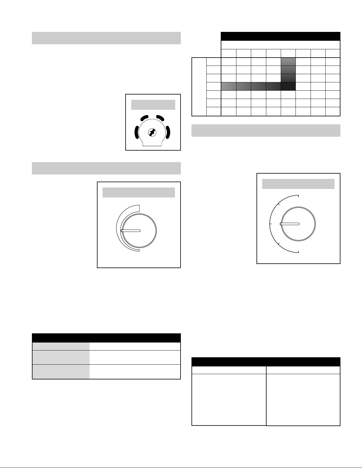
Red Diagnostic Light is on •Check that the wiring is correct. See Figure 7.
•Measure the resistance of the Outdoor Temperature Sensor by removing the leads from the terminal and measuring
the resistance across the wires with an ohmmeter. Confirm the reading with the temperature in Table 4.
(For Manual Operation, verify that the resistance across the leads of the Manual Mode Resistor Case is between
44,000 and 48,000 ohms).
Humidifier operates only
in “Test”mode
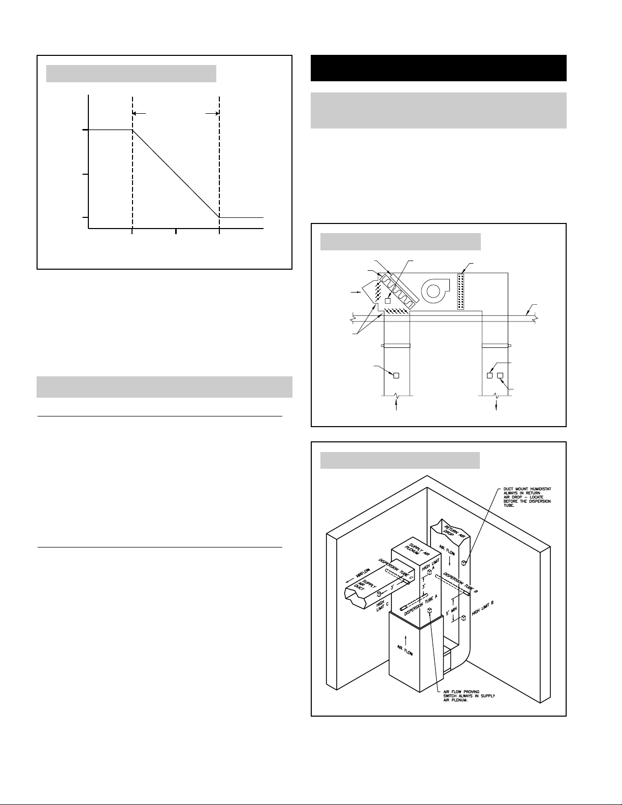
•If outdoor temperature is greater than 60°F or less than -30°F, the Humidistat will only
operate in the “Test”mode. (Automatic Mode Only)
•If the humidity level in the building is higher than the knob setting or the proportional
control band (DS 401 only), the Humidistat will not operate the Humidifier.
•Check the resistance of the sensor by removing the leads of the Outdoor Temperature
Sensor from the terminals and measuring the resistance across the wires with an
ohmmeter. Confirm reading to outdoor temperature in Table 4. (For Manual Operation,
remove leads and verify that resistance across the leads of Manual Mode Resistor Case
is between 44,000 and 48,000 ohms).
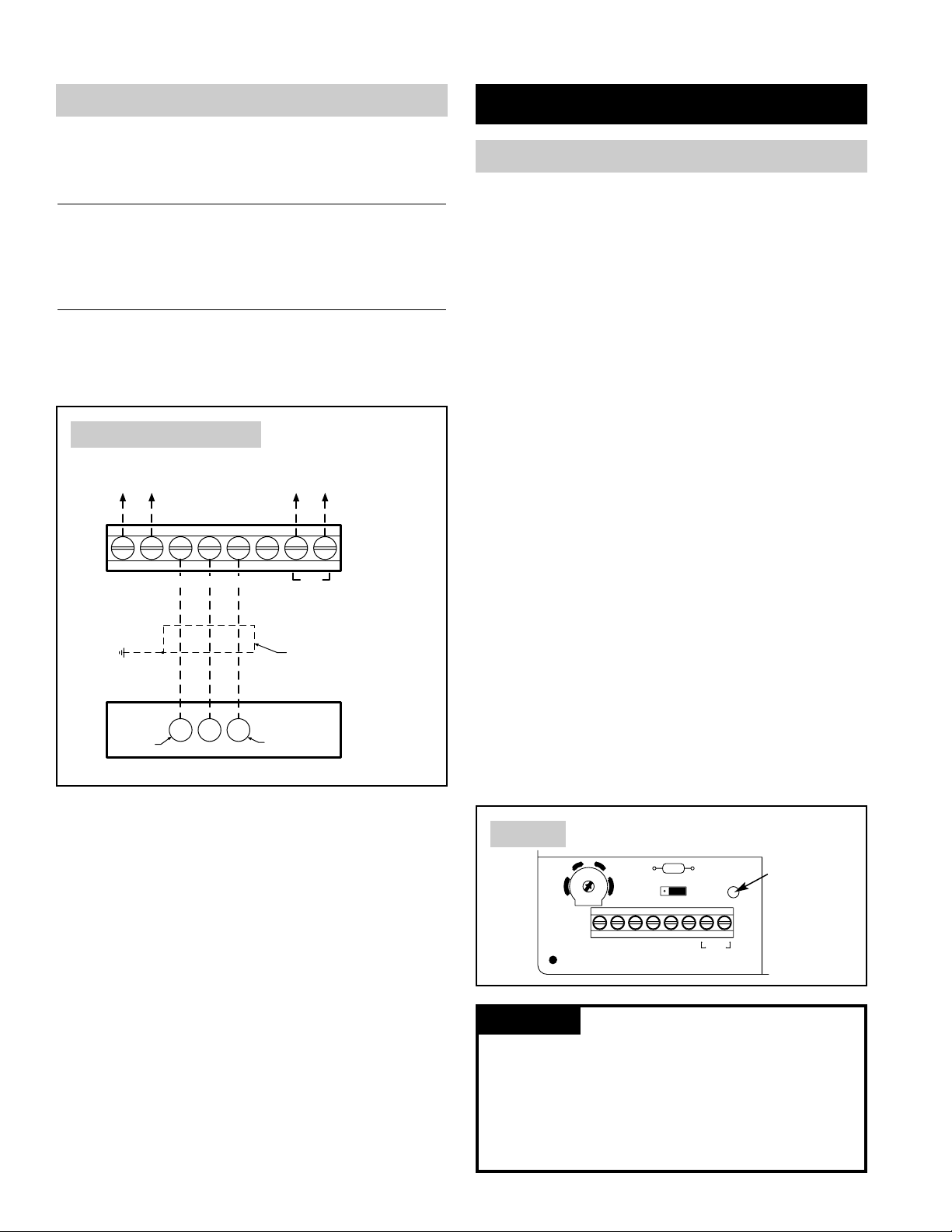
•Make sure the Outdoor Temperature Sensor is mounted completely outside the building on the
North, East, or West side of the building and out of direct sunlight. (Automatic Mode Only)
•If Outdoor Temperature Sensor is mounted in fresh air intake duct, make sure the probe is
no more than 36 inches from the outside wall. (Automatic Mode Only)
•Make sure the Outdoor Temperature Sensor is located at least 3 feet away from all
exhaust vents. (Automatic Mode Only)
Outdoor
Temperature
-30˚F
-20˚F
-10˚F
0˚F
10˚F
20˚F
30˚F
40˚F
50˚F
60˚F
70˚F
80˚F
90˚F
100˚F
Resistance
kΩ
230.6
163.8
117.6
85.4
62.6
46.3
34.6
26.1
19.9
15.3
11.9
9.4
7.4
5.9
TROUBLESHOOTING GUIDE
TABLE 4