Viconics Micro-stat H200 Series User manual

1
04/06/04 LIT-H200X-E02 H200.doc
ELECTRONIC HUMIDISTAT: H200
•ONE OR TWO STAGES
DESCRIPTION
The H200 series low voltage, microcomputer-based PI
(proportional and integral) humidistats are designed for
accurate humidification and/or dehumidification control
in non-corrosive commercial applications such as:
hospitals, schools, office buildings, retail stores,
museums, computer rooms, etc.
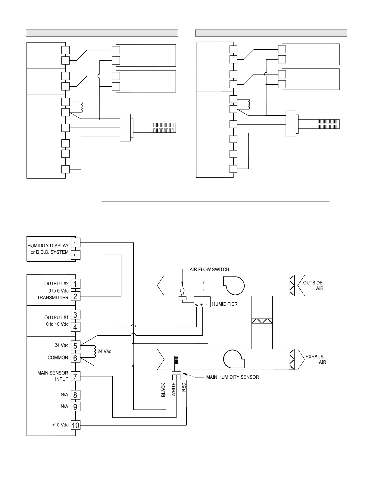
The H200 series is available with one or two outputs
for maximum flexibility. Outputs can be of the following
type: proportional, on/off, and pulse width modulation
(PWM). In addition, a wide variety of mounting
configurations is available. Sensing options include
remote duct and room as well as integral room and
duct.
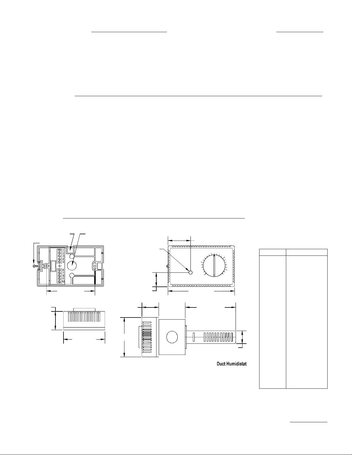
Setpoint adjustment can be either concealed or
exposed, adding even more versatility to the product.
Exposed models feature internally selectable minimum
and maximum setpoint knob stops.
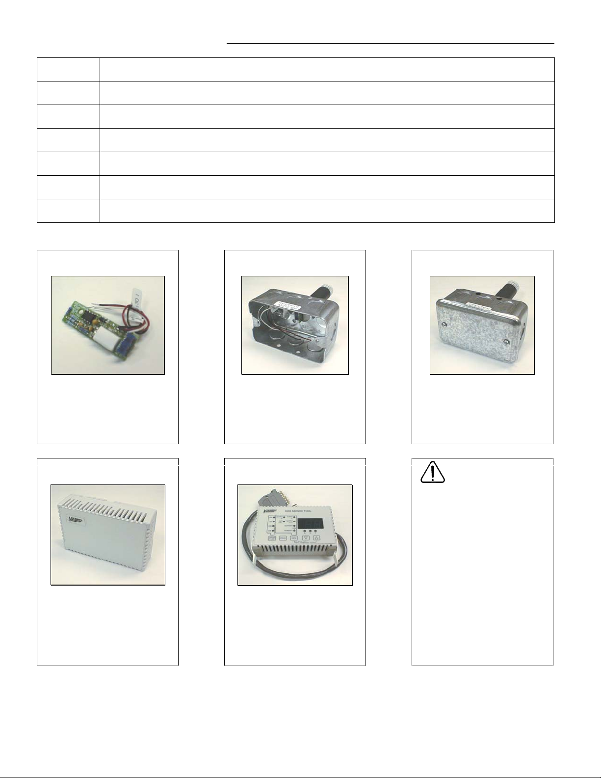
In order to facilitate periodic recalibration, the H200
series contains a unique autocal key, which permits
instant recalibration (see dimension drawing on page 5
for location).
Each humidistat is computer calibrated and factory
programmed with default parameters. All control
parameters (such as proportional band, stage
differential, etc.) may be changed in the field with the
H263 programming tool without having to remove the
thermostat cover. The H263 also doubles as a
diagnostic tool and indicates the status of all the inputs
and outputs, and will reduce troubleshooting time by
quickly identifying the specific problem.
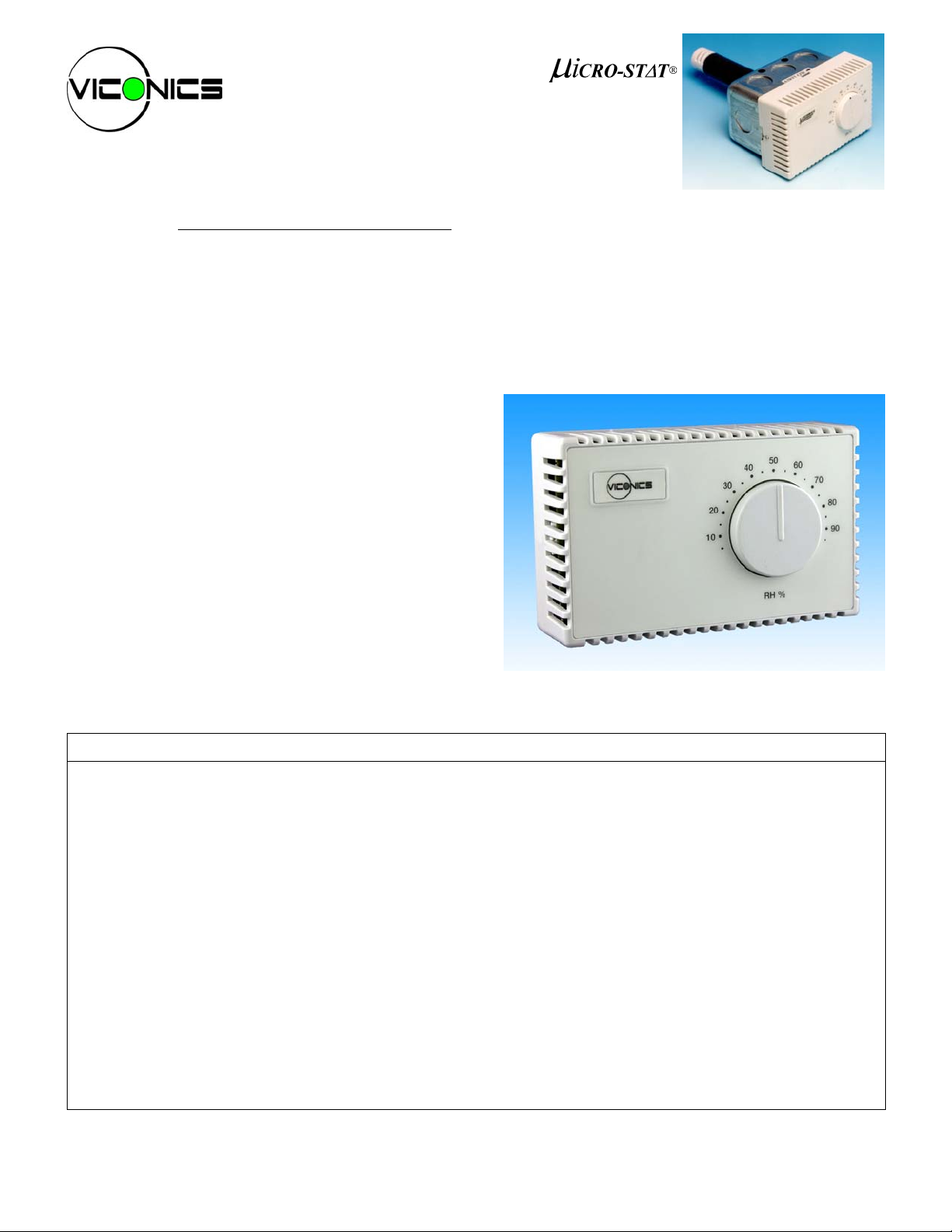
Fig.1: Wall mounted humidistat
Features Benefits
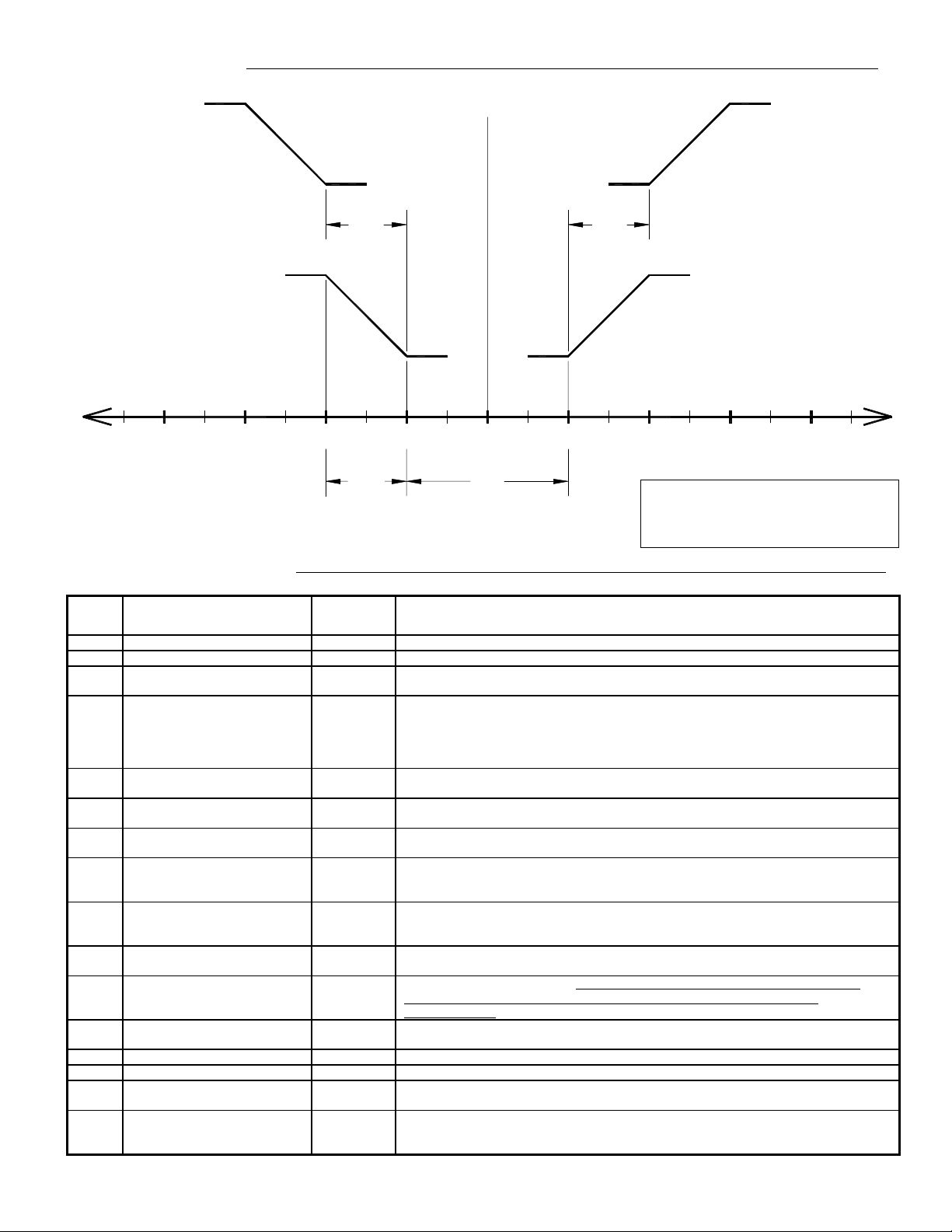
•Microcomputer-based design with PI algorithm ⇒Exceptional accuracy
•One or two outputs ⇒Controls humidification and dehumidification equipment
•On/off and/or proportional outputs ⇒Greater flexibility
•Direct or reverse acting outputs ⇒Controls humidification and dehumidification equipment
•Integrated and remote sensing ⇒Larger choice of mounting options
•Autocal button ⇒Permits instant recalibration
•Concealed or exposed set point ⇒Can be used in a large variety of environments
•Ouput signal to digital indicating devices ⇒Increases functionality of product
•Optional H263 diagnostic tool with digital display ⇒Simplifies troubleshooting
•Sensor failure protection ⇒Prevent water dammage
•CE approved ⇒Can be sold in European markets

2
04/06/04 LIT-H200X-E02 H200.doc
TABLE 1: ORDER CODE
H200 -A-B -C-D -E-F
AOutput no. 1 ( controlled device )
1 ON/OFF (15 min. time base)
4 (PWM) 24 VAC
5 (PWM) 5 VDC
6 Analog 0-10 VDC
BOutput no. 2 ( controlled device )
0 Not installed
1 ON/OFF (15 min. time based)
4 (PWM) 24 Volts AC
5 (PWM) 5 Volts DC
6 Analog 0-10 Volts DC
8 Signal transmitter 0-10 VDC
(1V= 10% , 9V-90%)
♦
9 Signal transmitter 0-5 VDC
(0.5V= 10% ; 4.5 V=90%)
♦
COutput no. 1 and 2 control mode
1Humidify
2 Dehumidify
3 Humidify ( no. 1 ) and dehumidify ( no. 2 )
4 Dehumidify ( no. 1 ) and humidify ( no. 2 )
DMain sensor location Sensor
0 Not installed None
1 Inside humidistat ( Local ) H50
2 Duct mount ( stat on duct ) H60
3 Duct mount ( stat on wall ) H71
4 Remote wall mount H80
ESetpoint adjustment
1 User adjustable
2 Blind cover
FFuture option
0 Unused
Example: H200 - 61 - 32 – 10
One “SCR” 0 to 10 volts humidify output and one relay
dehumidify output.
Humidistat and sensor are duct mount. Setpoint is user
adjustable.
♦Resolution: 0.5 % for retransmit only
See sensor specifications for dimensions of sensors
Note: the complete order code includes the sensor that will
be shipped with the humidistat.
WIRING
2 ON/OFF OUTPUTS
Single transformer
Fig.2: Wiring diagram with single transformer
Multiple transformers
Fig.3: Wiring diagram with multiple transformers
Note: Both of the above wiring diagrams show how to
wire output of type 1, 2, 3 and 4 (switched 24 Vac).
For outputs of type 5 and 6 (Vdc out) refer to Fig.4 and
Fig.5 on next page.
BLACK
COMMON 6
10
8
9
7
+10 Vdc
MAIN SENSOR
N/A
N/A
INPUT
HUMIDITY SENSOR
FOR CONTROL
RED
WHITE
4
5
1
3
2
OUTPUT #1
ON / OFF
24 Vac
OUTPUT #2
ON / OFF
24 Vac
24 Vac
24 Vac
+or 24 Vac VALVE
RELAY
-
or 24 Vac VALVE
+RELAY
-
BLACK
COMMON 6
10
8
9
7
+10 Vdc
MAIN SENSOR
N/A
N/A
INPUT
FOR CONTROL
HUMIDITY SENSOR
WHITE
RED
4
5
1
3
2
OUTPUT #1
ON / OFF
24 Vac
OUTPUT #2
ON / OFF
24 Vac
+or 24 Vac VALVE
RELAY
-
or 24 Vac VALVE
+RELAY
-

3
04/06/04 LIT-H200X-E02 H200.doc
2 PROPORTIONNAL OUTPUT
Fig.4: Wiring diagram with two analog outputs
1 PROPORTIONNAL AND 1 TRANSMITTER OUTPUT
Fig.5: Wiring diagram with one analog and one transmitter output
APPLICATION EXAMPLE:
Steam humidification system controled by a 0 to 10 Vdc valve wired to output #1. Remote humidity display using 0 to 5 Vdc signal is wired to
output #2. The humidity sensor is located in the return air duct.
Humidistat model number: H200-69-13-10
Fig.6: Application example
6
COMMON
N/A
INPUT
MAIN SENSOR
N/A
+10 Vdc
9
10
8
7
OUTPUT #1
TRANSMITTER
0 to 10 Vdc
0 to 5 Vdc
OUTPUT #2
24 Vac
0 to 10 Vdc 4
5
3
24 Vac
2
1
FOR CONTROL
HUMIDITY SENSOR
RED
BLACK
WHITE
DDC SYSTEM
ELECTRONIC MOTOR
or "SCR"
-
+
or METER
-
+
6
COMMON
N/A
N/A
INPUT
MAIN SENSOR
+10 Vdc
9
10
7
8
OUTPUT #1
0 to 10 Vdc
OUTPUT #2
24 Vac
0 to 10 Vdc 4
5
3
24 Vac
2
1
FOR CONTROL
HUMIDITY SENSOR
RED
BLACK
WHITE
ELECTRONIC MOTOR
ELECTRONIC MOTOR
or "SCR"
-
+
or "SCR"
-
+

4
04/06/04 LIT-H200X-E02 H200.doc
TABLE 2: HUMIDISTAT ACCESSORIES
H50 Internal humidity sensor for H200 humidistat and for H80 remote wall sensor.
H60 Duct humidity sensor to mount directly onto the back of any H200 humidistat.
H71 Duct humidity sensor to mount directly onto the supply or return of the ventilation duct.
H80 Wall humidity sensor to mount in any remote location.
H263 Programming tool for troubleshooting, viewing and modifying humidistat parameters.
008-0089 Replacement lexan (cover sticker) for H200 humidistat.
024-0048 Humidistat replacement base with connector (H50 internal humidity sensor not included).
H50 INTERNAL SENSOR H60 DUCT SENSOR H71 REMOTE DUCT SENSOR
This humidity sensor can be
mounted directly on 024-0048
humidistat base.
This humidity sensor can be
mounted directly onto the back of
any H200 humidistat, with the
supplied hardware. This
transforms the humidistat into a
duct-mounted humidistat.
This humidity sensor can be
mounted directly onto the supply
or return of the ventilation duct.
The H200 may be located on the
wall with humidity sensing from
the remote H71 sensor location.
H80 REMOTE WALL SENSOR H263 PROGRAMMING TOOL
This humidity sensor can be wall
mounted in any remote location.
The humidistat may be located
on the duct or other location, with
humidity sensing from the H80
sensor location.
This tool is used to change
humidistat parameters. It is also
useful for troubleshooting. Just
plug it in the humidistat through
the casing. See page 6 for more
details.
WARNING:
All H200 humidistats are
intended to control equipment
under normal operating
conditions. Where failure or
malfunction of H200 series
humidistats could lead to an
abnormal operating condition
that could cause personal injury
or damage to the equipment or
other property, other devices
(limit or safety controls) or
systems (alarm or supervisory)
intended to warn of, or protect
against, failure or malfunction of
H200 humidistats must be
incorporated into and maintained
as part of the control system.

5
04/06/04 LIT-H200X-E02 H200.doc
SET POINT
50%
db
OUTPUT #1
d2
HUMIDIFICATION
35%30% 45%40%
pb
0%
HUMIDIFICATION
100%
OUTPUT #2
100%
0%
d2
OUTPUT #1
DEHUMIDIFICATION
65%
55% 60%
0%
70%
DEHUMIDIFICATION
100%
0%
100%
OUTPUT #2
CONTROL SCHEMATIC:
TABLE 3: H200 PARAMETERS
CODE
VALUES DEFAULT
VALUE
DESCRIPTION
Db 0 to 40 % R.H. 25% R.H. Dead Band between humidification and dehumidification.
SL 30 to 100 % R.H. 85% R.H. Supply Limitation: High humidity limit in the supply duct (H270 only)
d2 0 to 199 % (of proportional
band)
100% Differential for output #2": Shift for output 2 relative to output 1
Pb 0 = 1.6 % R.H.
1 = 3.2 % R.H.
2 = 6.4 % R.H.
3 = 12.8 % R.H.
4 = 25.6 % R.H.
2= 6.4%
R.H.
Proportional Band
o1 0 = Humidification
1 = Dehumidification
"Output #1" Action for output no 1
o2 0 = Humidification
1 = Dehumidification
"Output #2" Action for output no 2
cc 2 = Without integral
3 = With integral
3 "Control Code"
t1 0 = On/off
1 = 8 minutes
2 = 1 second
"Time #1" Time period for output no 1
t2 0 = On/off
1 = 8 minutes
2 = 1 second
"Time #2" Time period for output no. 2
rA 0 = °C
1 = °F
1 DO NOT
CHANGE
"Range" Temperature Scale
Ca ±13 % Calibration ( deviation mode: DO NOT MODIFY: USE AUTOCAL PROCEDURE;
FOR H100 TRANSMITTER, USE THE ZERO POTENTIOMETER ON THE
TRANSMITTER.
hA 0 à 127 "Hardware assembly" Code related to thermostat model and entered at initial setup at
the factory.
it 1 to 99 = 1 TO 99 MINUTES 60 "Integral time" Error integration time.
Lt -40 à +40 °C (-40 à 105 °F) -20 °F "Lower temperature" minimum outside temperature for setpoint reset (model H270 only)
Ht -40 à +40 °C (-40 à 105 °F) 32 °F "Higher temperature" maximum outside temperature for setpoint reset (model H270
only)
rE 1 à 99 % R.H. 20 % R.H. "Reset” Minimum humidity value ( % HR ) (model H270 only)
Example: rE = 20%. Humidity setpoint will be reset from selected setpoint to 20%, from
Ht to Lt
pb = proportionnal band
d2 = differential between output #1 and #2
db = dead band between humidification
and dehumidification
Fig.7: Control schematic

Viconics Electronics Inc.
9245, Langelier Blvd, St-Leonard, Quebec, Canada H1P 3K9
www.viconics.com
sales@viconics.com
LIT-H200X-E02 H200.doc
6
"Autocal" button
(Invisible)
1.00" [25mm]
1.275" [32mm] Cover 1.275" [32mm]
2.8" [71mm] 2.8" [71mm]
3.275" [83mm]
Wiring from top
Security screw Base
Wiring from back
2.0" [50.8mm] 3.77" [95.8mm]
Cover
0.9" [22.8mm]
1.60" [41mm]
4.5" [114mm]
AUTOCAL PROCEDURE
1. Measure the room humidity near the Viconics
humidistat with an accurate hygrometer.
2. Turn the humidistat set point dial to match the reading
of the hygrometer.
3. Push and hold the autocal button for few seconds or
until the internal red light turns on. Look through the
slots on the left side of the humidistat.
SENSOR FAILURE PROTECTION
The sensor is the most sensitive part of the humidistat and
also the most exposed. In the case of a sensor failure in
humidification mode, the H200 will automatically assume a
failsafe output of 0%.
SPECIFICATIONS
Operating Conditions: 5 °C to 50 °C ( 32 °F to 122 °F )
•Control: 0% to 95% R.H. non-condensing
•Sensor: 0% to 100% R.H. (see Note 1.)
Resolution: ± 0.1 %
Repeatability: 0.5 %
Accuracy and sensor interchangeability:
± 2 % R.H. from 0 to 100 % R.H.
Range: 10 % to 90 % R.H. for 5 to 50 °C
(41 °F to 122 °F )
Temperature effect: 0.05 % / °F
Outputs: Isolated Triac: 30 Vac at ½ A max.*
0 to 5 VDC into 1KΩresistance min.
0 to 10 VDC into 2KΩresistance min.
0/5 VDC at 20 mA max.for both outputs
Power: 24 VAC -15%, +10%; 50/60 Hz; 2 VA
Base & casing: Off-white; self extinguishing
ABS plastic
*Triac outputs can only switch AC loads. Use relays when
switching dc loads.
Note 1. Humidity sensor: Solid state humidity sensor.
Suitable for normal, clean air. Not to be used in
corrosive or harmful environment.
DIMENSIONS
Note: Specifications and equipment are subject to change without prior notice.
TABLE 4: SENSOR
CHARACTERISTICS
Voltage between black and white
wire, terminals #6 and #7
HUMIDITY SENSOR OUTPUT
0 % 1.05 V
5 % 1.19 V
10 % 1.34 V
15 % 1.48 V
20 % 1.63 V
25 % 1.77 V
30 % 1.92 V
35 % 2.06 V
40 % 2.20 V
45 % 2.35 V
50 % 2.49 V
55 % 2.64 V
60 % 2.78 V
65 % 2.93 V
70 % 3.07 V
75 % 3.21 V
80 % 3.36 V
85 % 3.50 V
90 % 3.65 V
95 % 3.79 V
100 % 3.94 V
Fig.8: Dimension drawing
Table of contents