DriSteem TCI-W11-U-H Setup guide

1
Safety, Installation, and Operation Manual
DriSteem TCI-W11-U-H, TCI-W11-U Humidistat
READ COMPLETE INSTALLATION INSTRUCTIONS BEFORE STARTING.
WARNING
1. Contact with energized electrical circuits can cause
serious injury from electrical shock. Disconnect
electrical power to the humidifier before starting
installation.
WARNING This product must be installed by a qualified heating and air conditioning contractor. Failure to do so can
result in serious injury from electrical shock or damage to product, and can void product warranty due to
possible product misapplication.
CAUTION
1. Do not set humidity higher than recommended or
moisture can accumulate, which can cause bacteria
and mold growth or dripping water into building
spaces. Dripping water can cause property damage;
bacteria and mold growth can cause illness.
2. Do not set humidity up to recommended levels if
there is condensation on the inside of windows.
Condensation damage
can result.
THESE INSTALLATION INSTRUCTIONS ARE FOR THE HUMIDISTAT ONLY!
For DriSteem humidifier installation, follow DriSteem humidifier installation instructions.

2DRISTEEM TCI-W11 HUMIDISTAT INSTALLATION MANUAL
FEATURES
• Mount to wall or standard junction box.
• One universal input for a remote humidity sensor.
• Replaceable humidity element (TCI-W11-H)
• Standard with 3% humidity element (TCI-W11-H)
• One 0 - 10VDC or 4 - 20mA output*
• Input voltage of either 24VAC or 24VDC
*Actuators: Choose modulating actuators with an input signal type of
0 - 10VDC or 4 - 20mA (min. and max.signal limitations may be set
with parameters. 3-point point actuators with constant running time are
recommended).
SETTING PARAMETERS
The following functions can be changed from the parameters menu. Go
to www.dristeem.com to download the TCI-W11 Parameters guide or call
DriSteem Technical Support at 1-800-328-4447 for instructions.
• Configure universal input for a 0 - 10VDC, 2 - 10VCD, 0 - 20mA, or 4 -
20mA remote humidify sensor, default is 0 - 10VDC
• Configure output for 0 - 10VDC or 4-20mA, default is 0 - 10VDC
• Monitor alarms for high and low humidity, default disabled.
• Set min or max humidity display, default 0% and 100%
• Calibrate sensor
• Tune the PI control loop
• Enable security to prevent user from changing parameters.
WARNING!
This device is intended to be used for
comfort applications. Where a device
failure endangers human life and/or
property, it is the responsibility of the
owner, designer and installer to add
additional safety devices to prevent or
detect a system failure caused by such
a device failure. The manufacturer of
this device cannot be held liable for
any damage caused by such a failure.
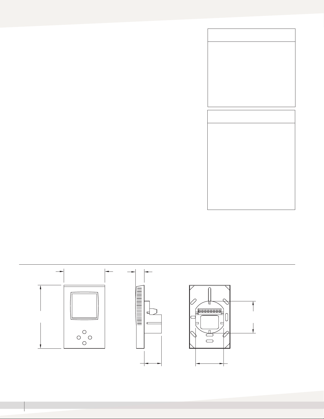
FIGURE 2-1: HUMIDISTAT DIMENSIONS
WARNING!
Live electrical components
During installation, testing, servicing
and troubleshooting of DriSteem
products, it may be necessary to work
with live electrical components. Have
a qualified licensed electrician or other
individual who has been properly
trained in handling live electrical
components perform these tasks.
Failure to follow all electrical safety
precautions when exposed to live
electrical components could result in
death or serious injury.
OM-8063
0.60" (15 mm)
2.25" (57 mm)
1.94" (49 mm)1.20" (30 mm)
4.43" (113 mm)
2.84" (72 mm)

3
DRISTEEM TCI-W11 HUMIDISTAT INSTALLATION MANUAL
Table 3-1:
TCI-W11 specifications
Power Supply
Power requirements 24 VAC ±10%, 50/60 Hz, Class 2, 2.0A, 48 VA max.
24 VDC ±10%
Power consumption Maximum 3 VA
Electrical connection Terminal connectors
0.34 - 2.5 mm2wire (AWG 22 - 13)
Signal Inputs
Universal input Setting for voltage or current
Input signal 0 - 10 V or 0 - 20 mA
Resolution 9.76 mV or 0.019 mA (10 bit)
Impedance Voltage: 98kΩ
Current: 240Ω
Humidity sensor AEs3-HT-Ax Capacity sensor
Range 0 - 100% rH
Measuring accuracy See Figure 4.2.
Hysteresis ±1%
Repeatability ±0.1%
Stability <0.5% / year
Signal Outputs
Analog output
Output signal DC 0 to 10V/0 to 20mA
Resolution 9.76 mV / 0.019 mA
Maximum load Voltage: 5kΩ
Current: 250Ω
Insulation strength between relays contacts and system electronics 2000 VAC to EN60730-1
Environment
Operation To IEC 721-3-3
Climatic conditions class 3K5
Temperature 0 to 50ºC (32 to 122ºF)
Humidity < 95% RH non-condensing
Transport & storage To IEC 721-3-2 and IEC 721-3-1
Climatic conditions class 3K5 and class 1K3
Temperature -25 to 70ºC (-13 to 158ºF)
Humidity < 95% RH non-condensing
Mechanical conditions class 2M2
Standards
conformity, EMC standard, low voltage directive
2014/30/EU
2014/35/EU
Product standards
Automatic electrical controls for household and similar use EN 60730-1
Special requirement on temperature dependent controls EN 60730-2-9
Degree of protection IP30 to EN 60529
Pollution class II (EN 60730-1)
Safety class III (IEC60536)
Overvoltage category I (EN60730-1)
General
Material: Cover, back part, mounting plage Fire proof ABS plastic (UL94 class V-0)
Galvanized steel
Dimensions (H x W x D) Front part: 15 X 113 X 72 mm (0.6 X 4.5 X 2.8in)
Power case: ø58 x 32 mm (ø2.3" x 1.3")
RoHS compliant according to 2011/65/EU
Weight (including package) TCI-W11 = 253 g (8.9 oz)

4DRISTEEM TCI-W11 HUMIDISTAT INSTALLATION MANUAL
Vertical bar
(scrolls up/down, 10%
resolution with current
output)
Small digits
Display of set point
Typical Home screen
Left (Power)
Press >2 s: Turn unit OFF. Text
OFF displayed
(Parameter setting: ENTER to
select menu option, accept
parameter change)
Large digits
Display value of humidity
Right (Option)
(Parameter setting: ENTER
to select menu option,
accept parameter change)
FIGURE 4-1: USING THE DRISTEEM HUMIDISTAT DISPLAY
Down
Decrease SET POINT
(Parameter setting:
SCROLL menu options
and parameters)
Off
Energy hold off:
Outputs are off,
inputs monitored for
alarms
Up
Increase SET POINT
(Parameter setting:
SCROLL menu options
and parameters)
DISPLAY INPUT VALUES (75%, UI1)
For TCI-W11:
• Press OPTION > 2 s: SEL and H-C
is displayed.
• Press UP key once: UI1 and its
value are displayed.
• UI1 is the remote duct humidity
sensor
FIGURE 4-2: HUMIDISTAT ACCURACY
TCI-W11-H Humidistat Accuracy
Percent Relative Humidity
Accuracy
010 90807060504030 100
20
±1
±2
±3
±4
±5
0
Note: Humidistat is most accurate at 77 °F (25 °C).

5
DRISTEEM TCI-W11 HUMIDISTAT INSTALLATION MANUAL
INSTALLATION
• Install the controller on an easily accessible interior
wall, approximately 1.5 m above the floor in an area
of average temperature.
• Avoid direct sunlight or other heat sources (e.g. above
radiators and heat emitting equipment).
• Avoid locations behind doors, outside walls,and below
or above air discharge grills and diffusers.
• Location of mounting is less critical if external sensors
are used.
• Ensure adequate air circulation to dissipate heat
generated during operation.
• Observe local regulations.
• Do not mount in a wet or condensation prone
environment.
INSTALLATION INSTRUCTIONS
1. Connect the wires to be connected to the terminals of
the power case according to wiring diagram.
2. Install the mounting plate to the flush mounting box.
Notes:
• Make sure the nipple with the front holding screw is
facing to the ground.
• Make sure the mounting screw heads do not stand out
more than 0.2" (5 mm) off the surface of the mounting
plate.
3. Ensure the jumpers are set correctly.
4. Slide the two latches located on the top of the front
part into the hooks at the upper side of the mounting
plate.
5. Carefully lower the front part until the interconnector
reaches the mounting-plate. Continue pressing in a
gentle way until the front part is fully connected. While
inserting the connectors, a slight resistance can be felt.
This is normal. Do not use excessive force.
6. With a Phillips-type screw driver of size #2, carefully
tighten the front holding screw to secure the front part
to the mounting plate. This screw is located on the
front lower side of the unit. There is no need to tighten
the screw too much.
JUMPER CONFIGURATION
Jumpers are mounted vertically only.
1. A0 - Selection of output signal type
• Left position: voltage output 0 - 10 V) factory
default.
• Right position: current output (0 - 20 mA)
2. UI - Selection of input signal type
• Left position: voltage input (0 - 10 V) factory
default.
• Middle position: current input (0 - 20 mA)
• Right position: RT or dry-contact input
FIGURE 5-1: CONNECTION
XH1
24 V AC/DC
0 V (COM)
2
G
YM1
XU1
1
G0
1
G0
7
X1
6
Y1
1
G0
Table 5-1:
Terminal connections
TCI-W11-U-H
(Room)
TCI-W11-U
(Duct)
G0 Ground 1 1
G 24VAC/21VDC 2 2
Y1 Control output 6 6
X1 Duct sensor Input — 7

Form No. TCI-W11-IOM-EN-1120
Part No. 890000--280 Rev A
DRI-STEEM Corporation
a subsidiary of Research Products Corporation
DriSteem U.S. operations are ISO 9001:2015
certified
U.S. Headquarters:
14949 Technology Drive
Eden Prairie, MN 55344
800-328-4447 or 952-949-2415
952-229-3200 (fax)
© 2020 Research Products Corporation
Table 6-1:
Troubleshooting guide
Issue
Power failure Check for proper supply voltage.
Check for wiring shorts; reset breaker.
Error message
Err1: An assigned input is not enabled or missing. All control loops, functions,
and outputs tied to this input will be disabled. Verify input connections, jumper
settings and parameter settings for the input involved.
Err3: A function refers to a disable input. Disable the function or enable the
input.
Err4: Internal failure. Product must be replaced.
Table 6-2:
Replacement parts
Model Description Part Number
TCI-W11-U-W26 kit 1 Model TCI-W11-U-W26, 1 duct sensor 600968
TCI-W11-U-W26
PI-controller, wall flush mounted int. 1 UI, 1 AO,
default: 0-10V input remote RH, 0-10V output
humidify
600966
TCI-W11-U-H-W24
PI-controller, wall flush mounted int. 1 UI, 1 AO,
int. humidity sensor 3% accuracy, default: humidity
control, int. RH, 0-10V output
600965
Accessories
Duct sensor, 3% 0 - 10V 600967
AES1-HT-A2 RH sensor 2% 600983
AES1-HT-A3 RH sensor 3% 600982
Other manuals for TCI-W11-U-H
1
This manual suits for next models
1
Table of contents
Other DriSteem Humidistat manuals