manuals.online logo
Brands
  1. Home
  2. •
  3. Brands
  4. •
  5. DRIZAIR
  6. •
  7. Water Pump
  8. •
  9. DRIZAIR 1200 User manual

DRIZAIR 1200 User manual

DRI-EAZ PRODUCTS, INC.
15180 Josh Wilson Road, Burlington WA 98233 •Tel: (360) 757-7776 Svc Fax (360) 757-6784 www.dri-eaz.com
PN 07-00397 Microswitch Kit Instructions - 2/28/02 1
DrizAir 1200/2400 Pump Troubleshooting Guide
All service procedures below are to be executed with the power off, i.e., unplugged.
Tools Required: (1) 5/16” Nutdriver or wrench (1) Phillips Screwdriver
(1) Flathead Screwdriver (1) Q-Tip Cotton Swab
(1) Needlenose Pliers (1) 6" x 8" piece of Cardboard
Preparation:
1. Read all pump and testing instructions carefully before
checking and servicing pump on dehumidifiers.
2. Make sure you have all the parts and tools required to
perform inspection, repair and upgrade as listed in these
instructions.
3. Make sure the dehumidifier is disconnected from the
power source before starting any of the following proce-
dures.
Removing Dehumidifer Cover and Accessing Pump
4. DrizAir 1200: Remove the six 3/8” bolts holding on the
front cover in the following order. While unit is standing
up, remove the two near the wheel axle. Place unit on its
back, remove the two located on top, in front of cover.
Last, remove the two located on bottom of unit near the
front feet. All bolts can be identified because they are all
3/8”. Remove front cover.
DrizAir 2400: Lay unit on its back and unscrew the four
7/16” bolts on the grey bucket. Remove bucket and turn
upside down. Then set the pump on it, using it as a table.
5. DrizAir 1200, Carefully snip the zip tie holding the coiled
power cord, and remove the two 5/16” mounting bolts lo-
cated to the rear of the pump with nut driver.
DrizAir 2400, Carefully snip the zip tie holding the power
cord in place inside unit.you may not need to snip the zip
tie if there is already plenty of slack in the power cord to
set pump on grey bucket. The objective is to remove the
pump just far enough to access the two Phillips screws
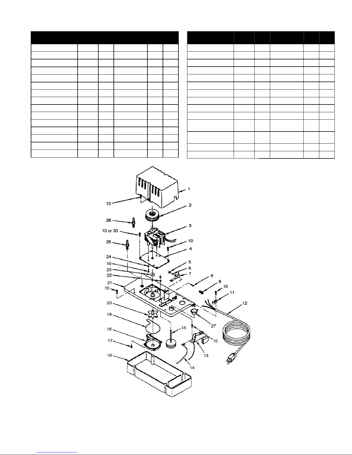
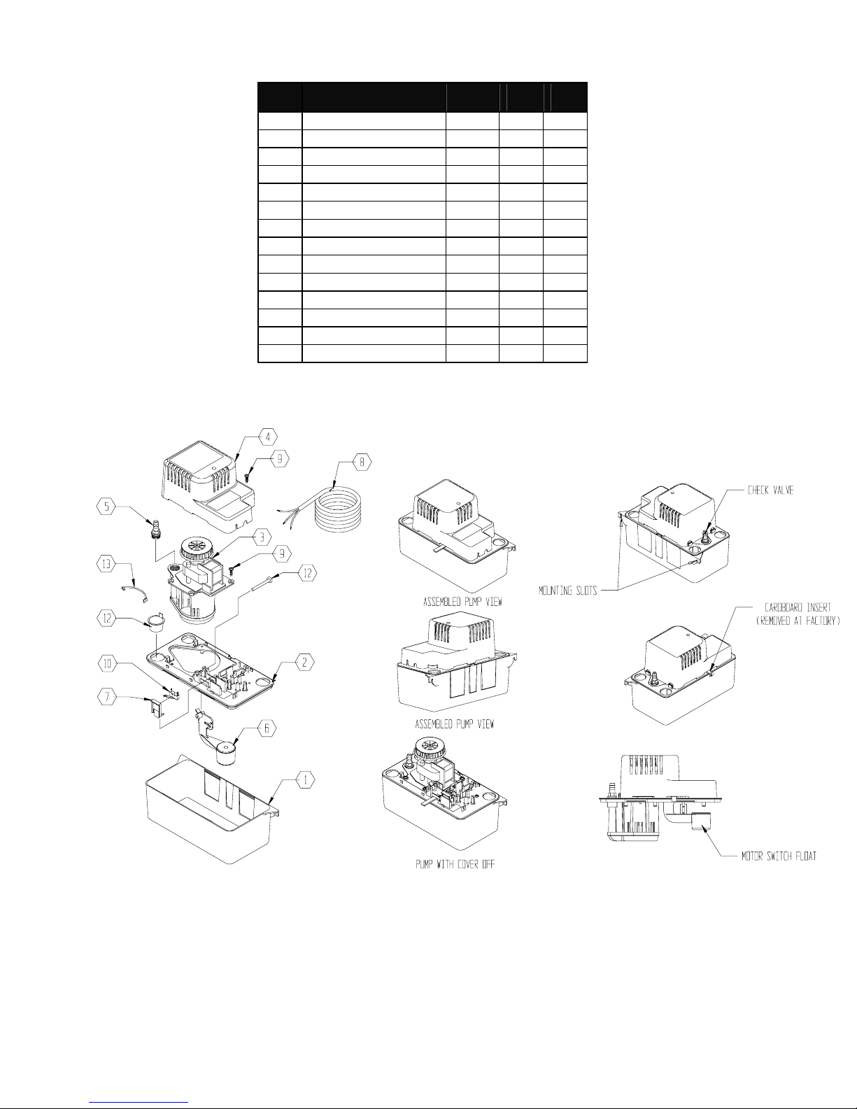
[#10], one on each side of pump cover [#1].
Inspecting External Pump Components
6. With pump exposed, inspect ½” clear drain tube entering
pump on right side to insure it’s properly seated into
pump. If too short or kinked it may need to be replaced.
7. Pull tube out and verify bottom of tube has a 35-degree
notch cut into it. This prevents a seal from occurring be-
tween the hose and bottom of resourvoir tank. If seal oc-
curs, water will back up in the drip tray and overflow.
8. Using screwdriver, remove pump-out tube from black
check valve [#25] located on left side of pump. Be careful
not to break fixture.
9. Unscrew check valve.
10. Look into the bottom of the check-valve assembly. Using
needle nose pliers carefully remove bottom of check valve
assembly by inserting one side of pliers approximately
1/8” into hole, grasp and pull carefully. A small bearing
should fall out so be careful not to lose it. Now you can
inspect for debris in assembly and clean accordingly.
Clean and reinstall.
Removing Pump
11. Remove pump from base by sliding to the left. While
slightly lifting the silver pump shield up, pull pump up and
out to left. Place piece of cardboard on top of refrigeration
coils and rest pump gently on top of it, using it as a table.
12.Remove two pump cover screws [#10], and set pump cover
[#1] aside.
Inspecting Internal Pump Components
13. With cover removed, visually inspect microswitch [#7]
for looseness. If loose, gently tighten screws [#8]. Note:
Over tightening will cause switch to bind up inside and
fail. If switch is snug and no parts missing, continue.
14. Check operation of microswitch by lifting float stem
[#15] upward, listening for the switch activation “click”
sound. Then, let float stem fall on its own, listening for
the “click” going downward. Switch may need adjusting
or replacement if “click” doesn’t occur in both directions.
Adjustment: The microswitch needs to be level to its
mounting peg. If switch is tilted too far back it will not
activate microswitch lever. Note: Do not bend mi-
croswitch lever to compensate for unevenness. Loosen
screws, adjust until level and gently re-tighten.
Replacement: If switch lever hangs up in either up or
down direction, replace microswitch.
Note: Be careful not to over tighten mounting screws and
nuts in either an adjustment or replacement switch situa-
tion. Also, be sure to include two locking washers [#6]
per screw, one underneath head of screw [#8] and one
prior to installing hex nut [#5].
15. Inspect to insure two “C”clips [#22] on float stem are in
place, one above and one below microswitch lever.
16. Check to insure float moves freely up and down and is not
restricted. If restricted, clean float stem [#15] and access
port. A Q-Tip works well for this procedure.
17. Check to see if impeller [#20] is spinning freely by spin-
ning the black plastic wheel located on top of motor.
18. Remove the remaining four Phillips screws [#10] from the
top of the pump assembly and separate it from the blue
reservoir tank [#16]. (Any missing microswitch screws or
nuts may be found here.)
19. Inspect bottom of reservoir tank for debris and dirt build
up. Clean accordingly.
20. Visually inspect impeller cover [#18] and gasket for
cracks, warps or exposed gasket material.
21. Remove four impeller cover screws [#17] and check for
debris in housing.
22. Assemble in reverse order. Run unit through several
pump outs to insure repairs.
SPECIFIC PARTS LIST FOR PUMP
PART REF# ITEM DRI-EAZ
PART NUMBER
QTY
115v
QTY
230v
Cover - motor 154006 1 - ••
Fan 154031 2 - ••
Motor - 115v 979554 3 - •
Motor - 230v 979555 4 -
•
Plate - Motor 154021 4 - ••
Nut - Hex, 2-54 920035 5 08-00300 2 2
Washer - Lock, #2 921027 6 08-00301 4 4
Switch - VC Pump 950337 7 08-00298 ••
Screw - 2-54 x 9/16” 901600 8 08-00299 2 2
Wire Nut 950403 9 - ••
Screw - 8-18 x ½” 902436 10 - 16 16
Strain Relief 154038 11 - ••
Wiring Harness - 115v 951556 12 - •
Wiring Harness - 230v 951222 12 - •
Lead Wire Assembly 951982 14 - ••
PART REF# ITEM DRI-EAZ
PART NUMBER
QTY
115v
QTY
230v
Float/Stem Assembly 154017 15 - ••
Tank 154004 16 -
••
Screw - 8-18 x ½”, SS 902431 17 - 5 5
Volute, Impeller Cover 154015 18 - ••
Seal Ring, Nitrile 928006 19 - ••
Impeller 154009 20 -
••
Cover, Tank 154005 21 - ••
Retaining Ring - circlip 923006 22 - 2 2
Washer, Slinger 921063 23 - ••
Washer, Lock, #8 921015 24 - 2 2
Check Value, VC
Assy
154715 25 - ••
Adapter, ¼” MNPT x
¼” Hose
154037 26 - ••
Plug, Drain Hole 929600 27 - ••
Screw, 8-32 x ½” 902421 28 -
DRI-EAZ PRODUCTS, INC.
15180 Josh Wilson Road, Burlington WA 98233 •Tel: (360) 757-7776 Svc Fax (360) 757-6784 www.dri-eaz.com
PN 07-00397 Microswitch Kit Instructions - 2/28/02 2
DRI-EAZ PRODUCTS, INC.
15180 Josh Wilson Road, Burlington WA 98233 •Tel: (360) 757-7776 Svc Fax (360) 757-6784 www.dri-eaz.com
DrizAir 2000 Pump Troubleshooting 7/30/02 3
DrizAir 2000 Pump Troubleshooting Guide
All service procedures below are to be executed with the power off, i.e., unplugged.
Tools Required: (1) 5/16” Nutdriver or wrench (1) 3/8 socket
(1) Phillips Screwdriver (1) 6 inch extension
(1) Pliers (1) ¼ inch drive extension
Preparation:
4. Read all pump and testing instructions carefully before
checking and servicing pump on dehumidifiers.
5. Make sure you have all the parts and tools required to
perform inspection, repair and upgrade as listed in these
instructions.
6. Make sure the dehumidifier is disconnected from the
power source before starting any of the following proce-
dures.
Removing Dehumidifier Cover and Accessing Pump
4. DrizAir 2000: Remove the (9) nine 3/8” bolts holding on
the front cover in the following order. Put down a drop
cloth, lay unit on its front cover. Looking down on ma-
chine locate and remove two (2) 3/8 bolts located between
the wheels. Remove three (3) 3/8 bolts located on bottom
of unit between wheels. Stand unit up. Remove two (2)
3/8 bolts located on top and in front of machine, remove
two (2) 3/8 bolts located just above air filter, one on each
side. With unit standing, remove cover. You will see the
pump located on the bottom and in the front of machine.
Lay unit on it’s back to work on pump. Snip the zip-tie
holding the coiled pump power cord and remove the two
(2) 5/16 screws holding pump to base plate.
Inspecting External Pump Components
6. With pump exposed, inspect ½” clear drain tube entering
pump on right side to insure it’s properly seated into
pump.
7. Verify tube is not plugged up with debris.
9. Using pliers, remove pump-out tube from black check
valve located on left side of pump. Be careful not to break
fixture.
9. Unscrew check valve.
11. Look into the bottom of the check-valve assembly. Using
needle nose pliers carefully remove bottom of check valve
assembly by inserting one side of pliers approximately
1/8” into hole, grasp and pull carefully. A small bearing
should fall out so be careful not to lose it. Now you can
inspect for debris in assembly and clean accordingly.
Clean and reinstall.
Removing Pump
11. Remove pump from base by sliding to the left. While
slightly lifting the silver pump shield up, pull pump up
and out to left. Do not place pump on coil assembly.
Place pump on newly exposed base plate area.
12. Remove one Phillips screw from the pump cover, set
pump cover aside.
Inspecting Internal Pump Components
13. With cover removed, visually inspect micro switch. If
switch is snug and no parts missing, continue.
15. Check operation of micro switch (#10) by lifting float
stem upward, listening for the switch activation “click”
sound. Then, let float stem fall on its own, listening for
the “click” going downward. This will ensure that switch
is not sticking. If switch sticks, replace.
15. Inspect to insure that the fulcrum lever attached to the
switch is properly placed between float activation pegs.
16. Check to insure float moves freely up and down and is not
restricted.
17. Check to see if impeller is spinning freely by spinning the
black plastic wheel located on top of motor.
18. Remove the pump motor assembly by pressing outward
on the reservoir (you will see a small cut-out for this on
the rear of the pump) and lifting up on motor assembly.
19. Inspect bottom of reservoir tank for debris and dirt build
up. Clean accordingly.
20. Visually inspect impeller cover for cracks, warps or any
foreign matter. Remove accordingly.
21. Remove any debris from drip tray area.
23. Assemble in reverse order. Run unit through several
pump outs to insure repairs.
SPECIFIC PARTS LIST FOR PUMP
ITEM DESCRIPTION REF# QTY
115V
QTY
230V
1 Tank, Black, ABS 154401 1 1
2 Tank Cover, ABS 154411 1 1
3 Volute Motor Assy 115v 154492 1
3 Volute Motor Assy 230v 154493 1
4 Motor Cover, ABS 154421 1 1
5 Check Valve 154715 1 1
6 Float Arm 154452 1 1
7 Switch Holder, ABS 154471 1 1
8 Wiring Harness Assy 951607 1 1
9 Screw – Tapping 8-18 x 5/8" 902414 5 5
10 Switch 950337 1 1
11 Drain Hole Plug, Red 929602 2 2
12 Float Pivot Pin 154455 1 1
13 Lead Wire Assy 954027 1 1
DRI-EAZ PRODUCTS, INC.
15180 Josh Wilson Road, Burlington WA 98233 •Tel: (360) 757-7776 Svc Fax (360) 757-6784 www.dri-eaz.com
DrizAir 2000 Pump Troubleshooting 7/30/02 4

Other manuals for 1200

2

This manual suits for next models

1

Popular Water Pump manuals by other brands

BUSCH R 5 series Installation and operation manual

BUSCH

BUSCH R 5 series Installation and operation manual

P.I.T. POG1100-P Operation manual

P.I.T.

P.I.T. POG1100-P Operation manual

Fluke Fluke-700LTP instruction sheet

Fluke

Fluke Fluke-700LTP instruction sheet

SAMES KREMLIN REXSON SH216 user manual

SAMES KREMLIN

SAMES KREMLIN REXSON SH216 user manual

Debem Equaflux 51 Instructions for use and maintenance

Debem

Debem Equaflux 51 Instructions for use and maintenance

LR-Cal LPP 08 operating manual

LR-Cal

LR-Cal LPP 08 operating manual

KSB Delta Macro F Installation & operating manual

KSB

KSB Delta Macro F Installation & operating manual

JS Pump RSD-400 Maintenance Guide

JS Pump

JS Pump RSD-400 Maintenance Guide

Pond Boss PW1250 manual

Pond Boss

Pond Boss PW1250 manual

Davey TotalFlo TF117MS Installation and operating instructions

Davey

Davey TotalFlo TF117MS Installation and operating instructions

Samoa LARIUS GIOTTO Operating and maintenance manual

Samoa

Samoa LARIUS GIOTTO Operating and maintenance manual

Dometic Gale 12V user guide

Dometic

Dometic Gale 12V user guide

Espa VE94 instruction manual

Espa

Espa VE94 instruction manual

GEA Hilge MAXA BLOC Translation of the original operating manual

GEA

GEA Hilge MAXA BLOC Translation of the original operating manual

MSW MSW-OBG80D user manual

MSW

MSW MSW-OBG80D user manual

Accudyne Industries Milton Roy MILROYAL C Installation, operation & maintenance manual

Accudyne Industries

Accudyne Industries Milton Roy MILROYAL C Installation, operation & maintenance manual

Wren KLW4100 Series Operation and maintenance manual

Wren

Wren KLW4100 Series Operation and maintenance manual

pumpa Black Line HMP Translation of the original instruction manual

pumpa

pumpa Black Line HMP Translation of the original instruction manual

manuals.online logo
manuals.online logoBrands
  • About & Mission
  • Contact us
  • Privacy Policy
  • Terms and Conditions

Copyright 2025 Manuals.Online. All Rights Reserved.