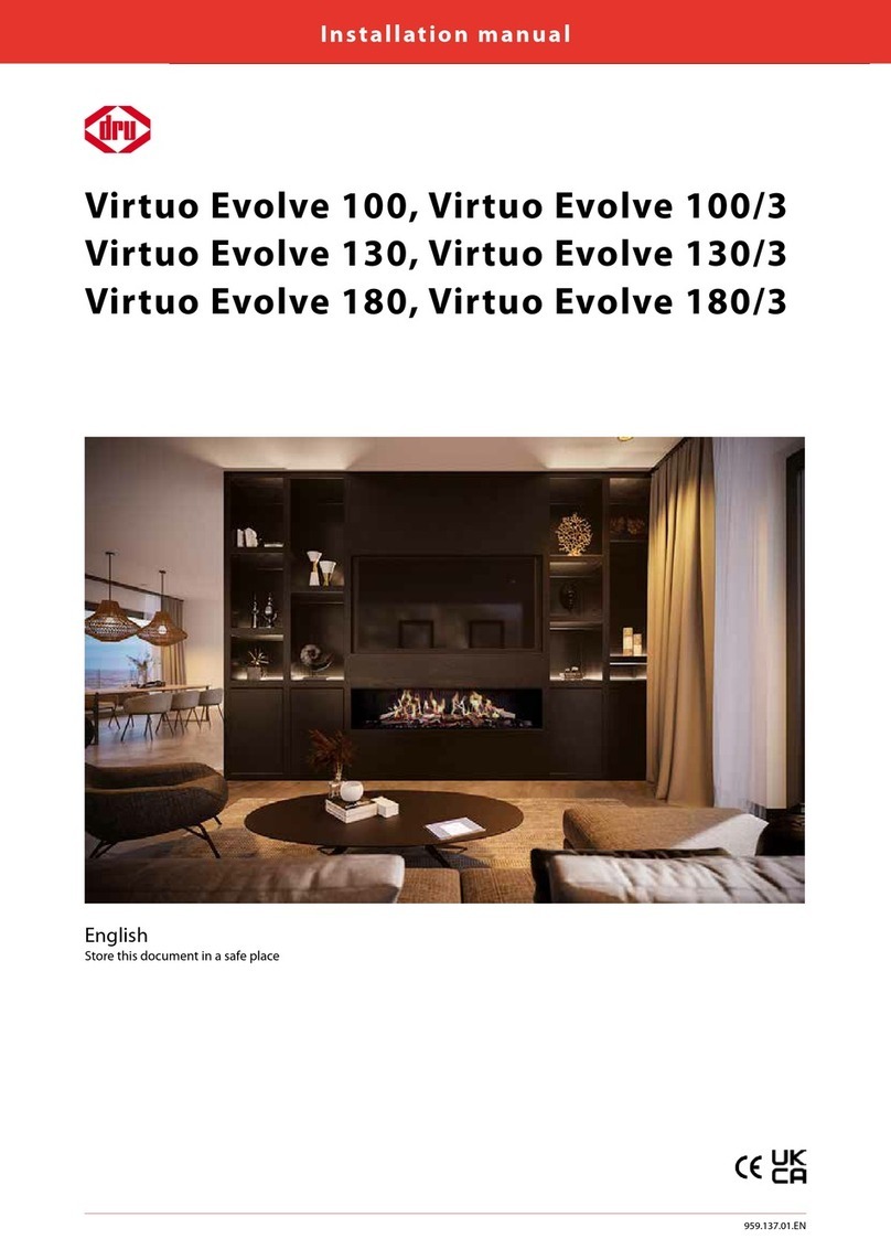
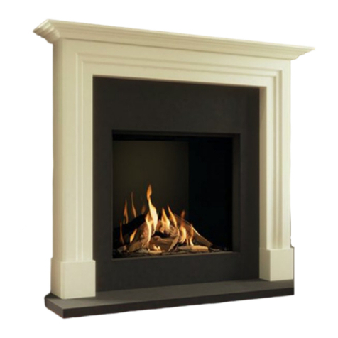
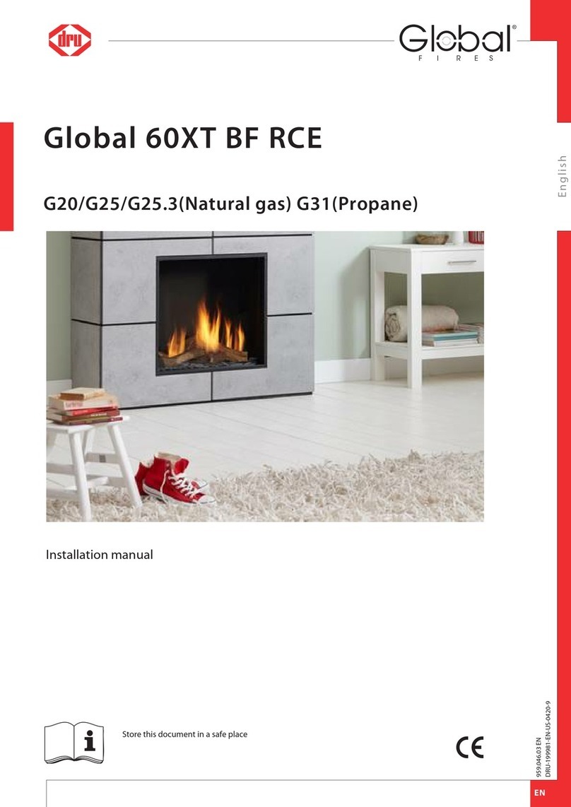
Dru Maestro 75XTU RCH User manual

Installation manualMaestro 75XTU RCHG20/G25/G25.3 (Natural gas), G30 (Butane) and G31 (Propane)EnglishStore this document in a safe place959.110.05.ENDRU-975797-EN-US-0721-1Scan this QR-Code forDRU Video Assist

Installation manual21. Step-by-step installation plan42. Introduction53. CE declaration54. Technical data65. SAFETY75.1 General75.2 Regulations75.3 Safety instructions76. Preparation86.1 Unpacking86.2 Type of gas86.2.1 Gas type conversion86.3 Gas connection86.3.1 Gas hose for gas connection96.4 Electric connection96.5 Components appliance control107 Installatie117.1 Placing the appliance117.2 Additional installation options137.2.1 Platform combined with lower decorative strip137.2.2 Platform connecting to the glass137.3 Concentric system177.3.1 General177.3.2 Roof terminal (C31)197.3.3 Wall terminal (C11)227.3.4 Connection to an existing chimney257.4 Placing the chimney breast257.5 Placing the control hatch288 Appliance308.1 Glass panes308.1.1 Removing the side pane308.1.2 Removing the front pane/rear pane.308.1.3 Placing the glass pane308.2 Setting the appliance328.2.1 Restrictor slide (R)328.2.2 Air inlet guide (L)338.3 Placing the wood set358.3.1 Wood set359. Control/operation459.1 Principle of ignition cycle469.2 Connecting the switch contact469.3 Connection extra power supply (max. 80W, 230VAC)479.4 Remote controls479.4.1 Black remote control for the user47Content

Installation manual39.4.2 Orange remote control for the installer479.5 Alternative operation479.5.1 Wired489.5.2 Wireless499.5.2.1 Connection via ‘modbus’ protocol499.5.2.2 Control via application4910. Final inspection5010.1 Gas tightness5010.2 Gas pressure/line-pressure5010.3 Ignition main burner5010.3.1 First ignition of the appliance after installation or adjustments5010.3.2 Procedure for igniting the main burner5110.4 Flame picture5111. Delivery5212. Maintenance5312.1 Parts53Appendix 1: Malfunctions54

1. Step-by-step installation planThe major steps of the installation are described below,Perform these steps and tick them once they have been performed correctly.3Carefully read the installation manual before installing the appliance.Installation manual4The appliance is now (after the above-mentioned steps) ready for use and the consumer is familiar with the possibilities for using the appliance.Check that the gas type and gas pressure is correct on the location where the appliance is placed.Check that the supplied parts are present (see table 6-1).Check the appliance for damages.Make sure that the total installation complies with the applicable national, local and architectural regulations.Make sure that there is a gas tap present that is always accessible and meets the legal regulations.Ensure that the placement meets the applicable requirements concerning fire safety.Make sure that the configuration of the concentric system with roof or wall duct corresponds with the imposed requirements (see section 7.3).Make sure the chimney breast meets the fire safety requirements. (see section 7.4).Make sure the chimney breast meets the minimum dimensions (see section 7.4).Make sure the chimney breast is sufficiently ventilated (see section 7.4).Make sure that the control hatch with gas control is placed correctly (see section 7.5).Make sure that the restrictor slide and air inlet guides are correctly adjusted (see section 8.2).Ensure a correctly placed wood, pebble set or broken glass set with accessories (see section 8.3).Make sure the remote control is made ready for use (see section 9.4).Check all gas connections for gas tightness (see section 10.1).Make sure that the appliance is first ignited without the glass pane (see section 10.3.1).Ensure a cleaned glass pane in accordance with the instruction, before the atmospheric fire is ignited with the glass pane for the first time (see chapter 12).Check the appliance with installed glass pane for a correct ignition and a correct flame transfer of the main burner(s) when igniting for the first time (see section 10/3/2).Familiarise the user with the appliance (see chapter 11).Check that the correct type of appliance has been delivered (see table 4-1).

2. IntroductionDRU, a manufacturer of gas-fired and electric stoves, develops and produces products that comply with the highest quality, performance and safety requirements. This appliance has a CE label, which means that it complies with the essential requirements of the European Gas Appliance Directive. The appliance is supplied with an installation manual and a user manual. Installation and maintenance of the appliance should be performed by a professional certified expert with a proven knowledge and demonstrable competence in this field.A professional expert takes all technical aspects such as heat output, gas connection and electricity into account, as well as the flue gas discharge requirements. The information in this installation manual will ensure the appliance is installed in such a way that it will function properly and safely. If the installation instruction is not clear, national/local regulations must be observed.This manual discusses the installation of the appliance and the regulations that apply to the installation. In addition, the appliance's technical data are shown and information is provided about maintenance, possible malfunctions that might occur and their possible causes.Fully and carefully read and use this installation manual, before installing the appliance. When using the DRU PowerVent® system or DRU CM system, the accompanying installation manual should also be read completely and carefully, before installation work begins.The following symbols are used in the manual to indicate important information:1Work to be performed2Suggestions and recommendations3You will need these instructions to prevent problems that might occur during installation and/or use.3You need these instructions to prevent fire, personal injury or other serious damages.After final delivery, the manuals should be handed over to the user.3. CE declarationDRU declares that company internal measures guarantee that appliances produced by DRU meet the essential requirements and guidelines of the regulation concerning gas-fired appliances and the accompanying standards. This declaration loses its validity if changes are made to the appliance without written permission from DRU. The instructions in the manuals must also be observed at all times. A copy of the CE test certificate can be downloaded via www.druservice.com. Product:Type:Product identification number:Conformity assessment body:Regulations:Directives:Standards:Gas-fired heating applianceMaestro 75XTU RCH0063CS3117Kiwa Netherlands B.V. (0063)Wilmersdorf 50Postbus 1377300 AC, Apeldoorn(EU) 2016/426, (EU) 2015/11882014/35/EU, 2014/30/EUEN 613:2000, EN 613:2000/A1:2003, EN 613:2000/PrA2:2002EN 60335-1:2012, EN 60335-2-102:2016, EN 55014-1:2007EN 55014-2:2015, EN 61000-3-2:2014, EN 61000-3-3:2013, prEN613:2018Installation manual5DRU Verwarming B.V.Postbus 1021, NL-6920 BA DuivenRatio 8, NL-6921 RW Duivenwww.drufire.comR.P. Zantinge, Managing directorDuiven, 09-02-2018

4. Technical dataCheck the technical data based on the table below.Installation manualGastype:Indirect heating functionalityDirect heat outputIndirect heat outputSpace heating emissions NOxHeat outputNominal heat outputMinimum heat output (indicative)Technical dataNominal heat input (Hs)Nominal heat input (Hi)Consumption maxConsumption minBurner pressure maxBurner pressure minMain burner injector Low setting injectorEfficiency class (EN613)Useful efficiency (NCV)**Useful efficiency at nominal heat outputUseful efficiency at minimum heat output (indicative)Auxiliary electricity consumptionAt nominal heat outputAt nominal heat outputIn standby modePermanent pilot flame power requirementPilot flame power requirement (if applicable)Energy efficiencyEnergy efficiency indexEnergy efficiency classSymbol PnomPmin ηth,nomηth,min elmaxelminelSB PpilotEEIG25/G25.3*No8.4-83,48,41,211,910,7129022317,54,32x ø1,621x ø1,70A****193,384,10,02360,01250,0026 -93AG31No9,5-51,59,51,912,511,546710027,39,02x Ø1,101x Ø1,15A****193,692,10,02360,01250,0026 - 93AG20No8,8-92,88,81,212,411,2119124013,94,42x ø1,621x ø1,70A****193,384,20,02360,01250,0026 - 93AUnit kWkWmg/kWhinput (GCV) kWkW kWkWL/hL/hmbarmbarmmmm %% kWkWkWkWG30No11,1-61,711,12,214,413,14098727,28,92x Ø1,101x Ø1,15A****194,392,20,02360,01250,0026 -94AType of heat output / room temperature controlSingle stage heat output, no room temperature control Two or more manual stages, no room temperature controlWith mechanic thermostat room temperature controlWith electronic room temperature controlWith electronic room temperature control plus day timerWith electronic room temperature control plus week timerOther control optionsRoom temperature control, with presence detectionRoom temperature control, with open window detectionWith distance controle option NoNoNoYesYesYes Yes***Yes***YesMaestro 75XTU RCHBuilt-inClosed combustionC11, C31, C91, C12, C32*****I2E+ I2E I2EK I2ELL I2H I2L I3B/P, I3+ II2EK3B/P II2H3+ II2H3B/P II2E+3+ II2E+3B/P Bio Prop. Bio Meth.200/130DRU LAS ES-I 200/130, DRU LAS ES-E 200/150/100,DRU LAS ES-I 150/100, DRU PV-I 100/60Separated ignition / ionization plugsYes150°C