DS Stoves Stoker User manual

Before you inst ll or oper te DS Stoker
Furn ce, you must:
- Re d ll instructions c refully
- Inst ll smoke nd c rbon monoxide
detectors.
MADE IN USA
By
D.S. MACHINE SHOP
Do Not
Discard
This
Manual
DS Stoker Furn ce
High Efficiency Auger Fed Rice Co l Stoker Furn ce
Model SF250
OWNER’S MANUAL
This Furn ce meets
U.S. Test St nd rd UL 391
CAN/CSA-B366.1

1. Read all instructions carefully before installing or operating any D.S. Furnace.
2. You must install smoke and carbon monoxide detectors before you install or operate any
furnace. Check your local codes, this installation must comply with their rulings.
3. Never leave furnace doors open when unattended
4. nstall a barometric damper in your chimney system.
5. Do not hook up a coal furnace to an aluminum type B gas vent. Use a code approved Class A
chimney that is equal or greater than the exhaust on the furnace, and a minimum of 20’ high.
6. On all new installs connecting to an existing chimney, a level 2 chimney inspection must be done
by a certified chimney sweep.
7. Clean chimney before installing furnace. f there is creosote attached to the liner you could create a
serious chimney fire.
8. Never leave children unsupervised when they are in same room as furnace. Provide a sturdy
barrier to keep children and pets a safe distance from the furnace, or they could get severely
burned.
9. Keep furnace area clear from all combustible materials, gasoline, and other flammable vapors
and liquids.
10. Do not burn garbage, gasoline, drain oil or other flammable liquids in or around furnace.
11. Do not operate furnace with fire or ash removal door open.
12. Use the required floor protection as shown on page 3.
13. Check the clearance to combustible walls and floors. (see page 3)
14. Do not allow anyone who is unfamiliar with the furnace to operate it.
15. Spend some time with your furnace to become well acquainted with the different settings and how
each will affect its burning patterns. t is impossible to state just how each setting will affect your
furnace because of variations in each installation, and chimney drafts.
16. Be extremely careful when removing the furnace ash pan. t can get very hot!
17. Make sure your single wall chimney connectors have at least 3 screws per joint.
18. Always use a mixing valve when hooking up a domestic coil.
19. The area in which the furnace is located must have an adequate amount of air for combustion.
Open basements without storm windows or tight doors generally provide adequate air infiltration. f
the furnace is located in a separate room with a tight door ventilation must be provided to and open
area within the building or to the outside. f the building is of tight construction with exhaust fans,
an outside air supply that is ducted into the furnace room may be required.
20. Keep all covers and shields in place while stoker is in operation.
21. Turn off and disconnect power before disassembling pot, performing any maintenance or repairs.
22. Use #641 Seal- t-Right caulking to seal all joints between furnace and auger pipe and any
connections to eliminate any carbon monoxide escaping furnace pot area. Carbon Monoxide can
cause sickness or death.
23. Do not operate furnace with a fuel draft exceeding -0.06 n. Water Column / 14.93 PA.
Safety Instructions
2
ALL FURNACES MUST BE INSTALLED BY A NFI CERTIFIED SPECIALIST AND PLUMBED BY A
QUALIFIED LICENSED PLUMBER OR D.S. IS NOT RESPONSIBLE FOR WARRANTY
Locating Boiler
1. The furnace must be placed on a solid non-combustible floor. f you have a combustible floor it is
required to use a floor protector per UL 1618.
2. t is recommended that the furnace be centrally located.
3. The most important consideration in installing your furnace is adequate clearance between the
furnace and any combustible surface. A furnace that is placed too close to a wall or to furniture can
cause a fire. See UL safety plate on furnace for clearances.
4. The type 1 floorboard must extend at least 16” beyond the front and 8” of the back, and sides, and
must extend under and 2” beyond either side of the single wall chimney connector if it’s elbowed
towards a wall.
5. The furnace must have its own flue. Do not connect this unit to a chimney flue serving other
appliances.
6. Connection of the furnace to the chimney should be made as directly as possible (6 feet maximum

horizontal) and not more than two bends. No reduction in flue pipe below the exhaust diameter
should be used. The pipe connecting the furnace to the chimney should be at least 24 gauge.
Thicker gauges are available and will resist corrosion longer
and need fewer replacements. Slope the flue pipe back
towards the heater, 1/4” per foot of horizontal run. That way
if any condensation forms in the pipe it will be carried back
into the heater. The connector pipe should be installed so
that the upper pipe section fits inside the lower section. This
way any condensation building up inside the pipe will stay
inside the pipe as it flows down the inside surface.
Horizontal pipe runs should have the pipe seams turned up
Particular attention should be paid
to the point where the flue passes
through a wall or ceiling. This pen-
etration should always be made
with a thimble, insulated pipe, and
then proper accessories following
manufacturers instructions.
Chimney connectors must not
pass through the ceiling,
concealed spaces, or enter the chimney in the attic, unless
proper clearance or insulated pipe is used following manufac-
turers instructions. REMEMBER that all single wall chimney
connector sections
should be connected
with at least 3 sheet
metal screws per joint.
A fire in the stack may
cause vibration and poorly fastened piping may come apart causing an extreme fire and smoke
hazard. Do not extend single wall chimney connector past the inside edge of the flue liner. f you
have a manufactured stainless steel chimney, attach single wall chimney connector to single wall
chimney connector adapter. Where the pipe connects to a masonry chimney, the flue to the chimney
should be larger than the single wall chimney connector so you can insert the pipe out to the inside
edge of the chimney, but not past. Then seal as tight as possible and cover with a trim collar.
3
Chimney Requirements
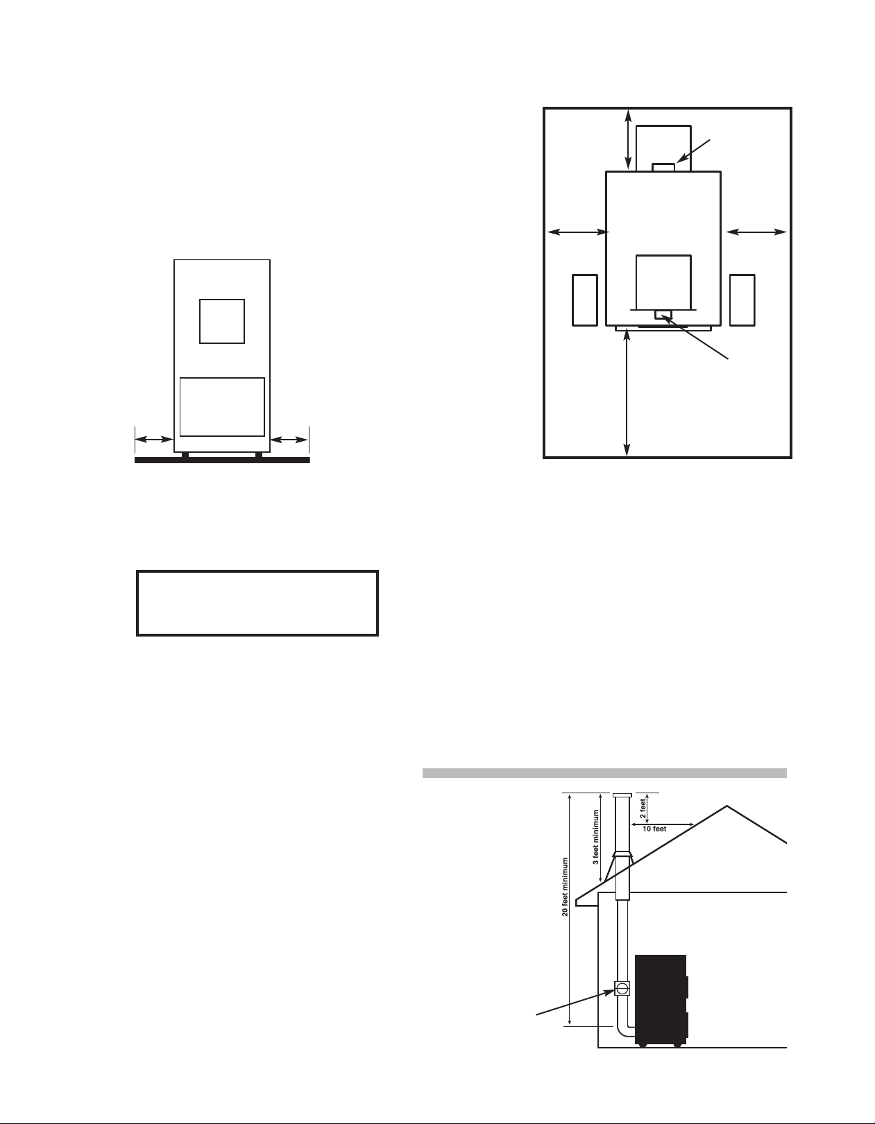
Use an 8” Class “A” approved chimney. Refer to manufacture’s instructions.
The minimum height of a chimney system for the D.S. Furnace
is 20 feet. The chimney must exceed the roof of a house at a
minimum of 3 feet at any point of exit. n a pitched roof installation
the chimney must be 2 feet higher than anything within a 10 foot
radius of the chimney. t is important to have a chimney draft of
-0.06 water column. t is required to abide by the manufacturer’s
instructions on Class A chimneys as well as local building codes.
t is not recommended to build a chimney on an addition that is
lower than the main part of your house. Do Not extend the single
wall chimney connector past the inside of a masonry chimney
liner. Never connect this unit to a chimney serving
another appliance.
Should you have a problem with inadequate draft
you should see page 15.
Minimum Clearance to Combustibles
Control side to comb stibles 21”
A ger side to comb stibles 12”
Back to comb stibles w/single wall stove pipe 30”
Back to comb stibles w/do ble wall stove pipe 18”
Top to comb stibles 18”
Front to comb stibles 36”
Single wall stove pipe to comb stibles 18”
Do ble wall stove pipe to comb stibles 6”
Top of plen m to ceiling 2”
Barometric
Draft
Control
CAUTION:
Keep furnishings and other combustible
materials away from the boiler.
Floor Protection
8” on back & 2 sides, 16” on front
Fig.1
A - Optional Control Box
Location
B - Limit Switch
C - Hot Air Outlet
D - 8” Exhaust
E - Cold Air eturn Box
8” 8”
Top View
Front
of Furnace
30”
12”
see
below*
12”
see
below*
36”
A
A
B
C
D
E

1. Set on noncombustible level hard surface
prepared for 850 lbs
2. See Label or page 3 for clearance to
combustibles.
3. When installing screws, nuts, bolts and
pipes, it is always important to use an
anti-seize compound to aid in future
removal.
4. Assemble side ash slides (2 pcs part
#SF250-RLAS) to inside control side mounting plates
(part #'s SF250-ASMP & SF250-CSMP) using 4-¼ x ¾ (F) Black hex bolts and
4-¼” (J) Zinc nuts. Assemble back ash slide (part # SF250-BKAS) to the back
baffle of stoker base. Using 2-¼ x ¾ (F) Black
hex bolts and 2- ¼” (J) Zinc nuts. Assemble front ash slide (part
#SF250-FTAS) to front panel of stoker base. Using 2- ¼ x ¾ (F)
Black hex bolt and 2- 1/4” (J) Zinc nuts. See Fig. 2.
5. Determine which side of furnace your coal hopper or coal bin will be.
Else right or left side. The coal hopper side is called the auger side
of furnace in this manual. The side opposite the coal hopper is
called the control side of furnace
6. nstall (part #SF250-ASMP) to auger side of furnace. Using 8 -
5/16×3/4 (D) SS hex bolts and 8-5/16” ( ) SS nuts. See Fig. 3.
7. Assemble pot assembly (part #SF250 pot-assem) to inside of
control side mounting plate (part #SF250-CSMP) using 4-5/16×3/4 (D)
SS hex bolts and 4-5/16 ( ) SS nuts. See Fig. 3.
8. Attach snap disc conduit with 90oconnector to #SF250-CSMP and insert snap disc wiring through
snap disc conduit. See Fig. 3.
9. Assemble auger motor to auger motor mounting bracket (part #SF250-AMM) using 4-bolts & nuts
provided with auger motor. nstall part #SF250-AMM to outside of part #SF250-CSMP using
2-5/16×3/4 (D) SS hex bolts and 2-5/16” ( ) SS nut. See Fig. 3.
10. nsert standard auger pipe (part #SF250-1AP) into stoker pot inlet and tighten 2-5/16 x ¾ (D) SS
bolts. See Fig. 3.
4
Installation Instructions
A - 3/8” x 71/2”
B - Auger Motor Bolt
and hardware
(supplied with auger)
C - 3/8” x 3/4” SS hex bolt
D - 5/16” x 3/4” SS hex bolt
E - 1/4” x 1” SS hex bolt
F - 1/4” x 3/4” Black hex bolt
SF250-RLAS
SF250-RLAS
SF250-FTAS
SF250-BKAS
Fig. 2
Chart 1
C
A
M
DF
SF250-PTOP
SF250-9R
SF250-8R
SF250-7R
SF250-6R
SF250-5R
SF250-4R
SF250-3R
SF250-2R
SF250-1R
SF250-CSMP
SF250-POT
Assembly
Combustion
Blower
Shear Pin
Auger Motor
Snap Disc
Wiring
Snap Disc
Conduit
SF250-P
SF250-ASMP
SF250-1AP
SF250-PCO
SF250-RLAS
(right & left)
SF250-FTAS (front)
SF250-BKAS (back)
x4
x4
x4
Dx2
E
x4
x2
Fig. 3
Seal Point
Fig. 3 NOTE: When assembling pot do not o er tighten
Pot Rings. Make sure they are centered or your pot fire
will not be centered.
H - 3/8” SS nut
I - 5/16” SS nut
J - 1/4” Zinc nut
K - #14 x 3/4” Black head
self-tapping screw
L - #8 x 3/4” Black head
self-tapping screw
M - Shear Pin SF250-SPIN 1/8
H round 2” long with
0.04 x 0.8 hairpin
SF250-AMM

5
Installation Instructions
11. Disassemble Pot Ring #SF250-PTOP from pot assembly. nstall part #SF250-CSMP on control
side of furnace using 8-5/16 x ¾ (D) SS Hex bolts and 8-5/16” ( ) SS nuts. nsert short auger pipe
through inside of stoker furnace and out the 2-7/16” hole of part #SF250-ASMP. See Fig. 3.
Reassemble Pot Ring #SF250-PTOP to pot assembly. See Fig. 3 Note.
12. nstall electrical control box on the control side of furnace using 2-#14 x ¾ (K) self tapping screws.
See Fig. 4
13. Remove pot insert part #SF250-P from bottom of pot see Fig. 3, page 4. nsert main auger
through short auger pipe on auger side of furnace and attach to auger motor on control side of
furnace using shear pin (M). See page 5, Fig. 3. Re-install pot insert. Note: You must remove pot
insert from pot bottom to install or remove short auger.
14. Seal all joints where auger pipe exits furnace, and where pipe coupler is used for 5’ and 8’ auger
extension option, seal both ends of pipe coupler as well as where you enter your hopper or bin.
Use #641 Seal- t-Right caulk. Provided with furnace. See Figs. 3, 14, 15, 16.
15. nstall limit switch on top plenum of furnace by hot air duct work outlet see Fig. 4. See page 6 for
limit switch wiring diagram.
16. Assemble motor cover box using #8 - 1/2” screws provided with unit. You must bend out the tabs
on the control side of furnace for the motor cover box tabs to slide into. See Fig. 4.
17. Assemble filter box for back of unit. Following instructions with filter box. You can assemble filter
box to have filter on right or left side of furnace. Do not install top of filter box until filter box is
screwed to back of unit. Screw filter box to back of unit, do not completely tighten the 2 top screws
because you need room to slide the top of filter box in behind these screws. nstall blower on back
of unit, connect conduit from electrical box to hole in the top of filter box. Connect the 5 wires in
conduit to the 5 wires on blower using the 5 wire nuts in hardware bag provided with the furnace,
connect white wire to purple wire, green wire to green wire, red wire to red wire, blue wire to yellow
wire and black wire to black wire. nstall top of filter box and tighten top 2 screws on back
accessing thru filter box opening. nstall 20” x 20” pleated filter.
18. nstall a barometric damper in your chimney system. With furnace operating at normal temperature
adjust barometric damper so that you have about a negative .05 or negative .06 inches of water
column in your single wall chimney connector approx. 12” below barometric damper.
See page 3, Fig. 1.
19. Have a licensed electrician connect all your wiring. Make sure all power is disconnected from
furnace before opening control box. Connect limit switch and snap disc wiring to control box as
shown in wiring diagram. See Fig. 5.
20. Hook up return duct to return box at back of unit.
21. nstall thermostat and hook up thermostat wire to thermostat wire connectors on control box.
)
)
)
)
)
)
)
)
)
)
)
)
)
)
)
)
)
)
)
)
)
)
)
)
)
)
)
)
)
)
)
)
)
)
)
)
)
)
)
)
)
)
)
)
)
)
)
)
)
)
)
)
)
)
)
)
)
)
)
)
Limit Switch
located on
front duct work
panel
Control Box optional
right or left side
Motor Cover Box
optional right or
left side
Fig. 4
Bend out 2 tabs for motor
cover shield to slide into.

6
FURNACE MUST BE WIRED BY A QUALIFIED LICENSED ELECTRICIAN OR D.S. IS NOT RESPONSIBLE FOR WARRANTY
Installation Instructions
Limit Switch and Pot Snap Di c
Wiring Diagram
Blue is
High Limit
Side
Back
Inside Panel
Limit Switch
Yellow is
distribution
blower side
Wiring diagram with all wires included

7
FURNACE MUST BE WIRED BY A QUALIFIED LICENSED ELECTRICIAN OR D.S. IS NOT RESPONSIBLE FOR WARRANTY
24 Volt Wiring Diagram 120 Volt Wiring Diagram

8
Typical Installation
YOU MUST INSTALL A SMOKE AND CARBON
MONOXIDE DETECTOR BEFORE INSTALLING
THIS UNIT
Below is a typical way to install a stoker add-on
furnace. n case of power outage you should always
run the hot air plenum up so that it can circulate by
gravity. The supply duct must be constructed of
material with a minimum 250otemperature rating.
f you are using this unit as an add-on furnace,
locate as close to the central furnace as possible.
NO E: Do Not use a chimney serving
another appliance!
Fig. 9
240 Volt Wiring Diagram

9
Optional Domestic Coil Hook Up
– Must have Aqua Pure or any water softener system when using coil to heat water –

10
Operating Instructions
Chart 2
Starting a fire
1. Turn switch on top of control box to on.
2. Push 60 minute timer start button. See page 7, Fig. 7 for start button location.
3. Turn on auger. Set auger speed to high setting and fill stoker pot to top ring. Turn off auger.
4. Bury stoker starter package in center of pot with just the fuse exposed. Or wrap shavings or saw
dust in news paper and partially bury in coal.
5. Use torch or lighter to ignite stoker starter or newspaper.
6. Turn combustion blower on high.
7. Wait till well started then add more coal to top of shavings and newspaper package.
8. When you have blue flames coming off of stoker pot, turn on auger and set combustion blower and
auger speed setting to desired heat setting. Adjust thermostat to desired heat setting. See Chart 2
below.
9. Must empty ash pan before it overflows. Empty ash pan regularly.
Adjusting he Coal Feed Rate
1 The coal feed rate determines the output of the furnace. See chart below.
2 The coal feed rate is adjusted by changing the RPM's of the auger. This is done by adjusting the
auger speed control up or down.
3 You may need two feed rate settings. One for spring and fall and one for winter time. During the
heating season, the feed rate will have to be raised to provide sufficient heat for load conditions.
This feed rate may cause outfire conditions during the time you are only maintaining pot fire for
warmer seasons. See outfire section. t is recommended to record both spring/fall and winter
combustion air and coal feed rate settings for easy reference.
Adjusting he Air Supply
1 Whenever the coal feed rate is adjusted, the air supply setting needs to be adjusted as well. See
chart below. These are approximate settings and may vary according to draft conditions and coal
quality. The numbers on the auger speed control are not intended to coincide with the numbers on
the blower speed control.
2 t may be necessary to adjust the air supply a few times to find the desired setting. With a proper
adjusted fire there will be approximately a 2” wide ash ring around outside of burner ring with a
small dark circle in the center of the pot. This is the fresh coal entering into the bottom center of
the pot. With too much air, the fire bed will tend to develop cracks. The dark spot in the center of
the pot will disappear. With too little air, the ash ring will be very small, hot and dark, falling off the
burner ring into the ash pit and the dark spot at the center ring will be large.
3 Some unburned coal in the ash is normal and indicates a well adjusted fire for maximum
efficiency. This amount must be small. Excess unburned coal indicates poor air/feed adjustment or
a poor grade of coal. n some cases, what appears as unburned coal may be slate or other foreign
material.

11
Interval imer Operations
nterval timer is what keeps your pot fire lit while the thermostat is not calling for heat. You may need
a higher setting during spring and fall than you will in colder temperatures.
Set interval timer so that it runs about 2 minutes every hour. deally 40 seconds on time for every 20
minutes off time. This is just a suggested starting point. You will need to adjust to your setup. Chimney
draft and coal quality play a role in the required run time of your stoker. f your run time is too high your
distribution blower may turn on and distribute heat when thermostat does not have a call for heat. When
interval timer setting is to low, you will experience an outfire. When this happens you need to increase
the on time and decrease your off time.
The following list is on and off time for each nterval Timer Setting.
1. 20 Seconds On – 30 minutes off.
2. 30 Seconds On – 30 minutes off.
3. 20 Seconds On – 20 minutes off.
4. 30 Seconds On – 15 minutes off.
5. 30 Seconds On – 20 minutes off.
6. 40 Seconds On – 20 minutes off.
7. 40 Seconds On – 15 minutes off.
8. 50 Seconds On – 15 minutes off.
Winter Month Operation
During the heating season, the feed rate will need to be adjusted to provide sufficient heat for load
conditions. See chart 2 on page 10 for output settings. nterval timer settings should be about 30
seconds every 30 minutes for your peak heating season.
Out-Fire Situation
1. s power indicator light ON? f light is ON this indicates that the furnace still has power and is
trying to function. f light is OFF this indicates that furnace has shut down due to pot out-fire
situation.
2. Check shear pin. f sheared, replace shear pin (part #SF250-SP N) see page 4 Chart 1.
3. A stoker fired furnace must run periodically to maintain a pot fire even though there is no call for
heat by the thermostat. This is accomplished by the interval timer. A normal run time in the peak
heating season is approximately 30 seconds every half hour. This is a suggested start and times
may have to be adjusted to meet conditions and time of year. Due to the wide range in the quality
of coal, a timer setting of 2 minutes per hour may produce an acceptable burn. ts an
experimental process of timer run times, air and feed settings, with the two main objectives being
a proper ash ring (2 inches) and a fire that does not burn deeply into the pot. You may need a
spring / fall setting and a winter setting. t is recommended to record your settings for future
references.
4. An outfire in the stoker is a more prevalent condition during the spring / fall months. t can happen
even though you find nothing wrong with the stoker mechanically.
Snap Disc Function
1. The snap disc is located on the outside bottom of the main pot ring towards the front, behind the
front ash slide inside the ash door.
2. The snap disc will sense the temperature at the pot. f the temperature at the pot drops below 90
degrees Fahrenheit the snap disc will shut off. This will shut power off to the unit. You can push
the 60 minute timer button to override this snap disc for 60 minutes. This should provide enough
time to relight furnace and get the pot temperature above 120 degrees where the snap disc will
reconnect and the furnace should function. f it does not function see Out-Fire situation.
Note on Limit Switch settings: The L4064B2236 limit switch has three settings
1. The High Limit Setting: This shuts the stoker off when the limit switch reaches the temperature
setting. t overrides all other controls. (Distribution blower will keep running, Stoker will shut down)
Factory setting is 215 degrees Fahrenheit.
ALL FURNACES MUST BE INSTALLED BY A NFI CERTIFIED SPECIALIST AND PLUMBED BY A
QUALIFIED LICENSED PLUMBER OR D.S. IS NOT RESPONSIBLE FOR WARRANTY
M

12
2. The Low Limit Setting: This turns off distribution blower when limit switch temperature drops
below this set point. (Only turns off distribution blower, stoker will still be able to run) Factory
setting is 100 degrees Fahrenheit.
3. The Middle Limit Setting: This turns distribution blower on when limit switch temperature rises to
set point. Distribution blower will stay on until limit switch temperature drops below the low limit set
point. (This only turns on distribution blower. t does not interrupt operation of stoker in any way) Factory
setting is 170 degree Fahrenheit.
• Loss of Draft: This can occur during hot, humid summer weather, with low fire in burner.
Changing the number of minutes of run time per half hour, increasing slightly the coal feed and air set-
tings may help. Thoroughly clean the furnace flue pipe and chimney. Remove fly ash buildup in furnace
by removing clean out plates and removing fly ash from furnace. Check to make sure all openings that
could infiltrate air from furnace base are sealed either by gaskets or seal it right caulk.
• oo much Draft: This is most likely to happen during cold, windy weather where there is no baro-
metric damper installed in chimney pipe. n this situation the fire continues to burn, even though the
stoker is not on. Adding a barometric damper and or properly adjusting barometric damper can help.
Adjust barometric damper so that you have about a negative .05 or negative .06 inches of water column
in your single wall chimney connector between your barometric damper and where single wall chimney
connector enters the furnace. Exhaust fans can also cause this problem by drawing air down the chim-
ney, through the burner and out of the housing inlet. This can be corrected by providing adequate out-
side air openings for both the stoker and the exhaust fan or discontinuing the use of exhaust fan.
Cleaning and Maintenance
• Turn off all power supply or disconnect power cord before attempting any maintenance.
• We recommend that you completely clean out stoker pot immediately after unit is shut off and
cooled down for the summer. Take auger out of auger pipe and completely clean out left over coal, this
will help reduce corrosion. Spray full inside with vegetable oil. f furnace is located in a damp
atmosphere it is recommended to put heat lamp inside furnace to reduce corrosion while furnace is not
running.
• Clean out fly-ash every 1,000 hours or at least once annually. You can expect fly-ash buildup
behind baffle in the base of unit and under pot rings. (remove pot rings once annually to remove fly ash.)
Remove all clean out plates from furnace, (including pot insert clean out on bottom of pot assembly) and
remove fly-ash with ash-vac or by just cleaning out manually. Also remove single wall chimney connec-
tor from furnace and remove fly-ash. There may be some fly-ash buildup in the single wall chimney
connector elbow.
• Check all gaskets and sealer joints for cracks or leaks annually. Replace gaskets or seals as
needed.
Coal
1. Use rice sized coal in your stoker furnace. With not more than 10% oversize and not more than
15% under size. Not following these guide lines will result in poor combustion.
2. Avoid using wet coal, this will retard combustion and increase carbon monoxide output.

13
Coal Storage
1 - Provide an adequate amount of coal
storage for your boiler. Preferably
indoors in the form of an optional
manufactured coal hopper or coal bin
within the same room as your boiler.
deally your coal bin will be located so
that your coal supplier can access your
coal bin from the exterior of your
building. We recommend that you
contact your local coal supplier for
recommendations on this matter.
2 - f you purchased the optional 500 lb
coal hopper that is available with this
stoker boiler it gets attached to the end
of the short auger coming out of boiler.
This can be located on either the right
or left side of boiler. Make sure you put
sealant around auger pipe where it enters
hopper. Because of carbon monoxide keep hopper lid
closed when not loading coal. (very important)
3 - Never hook 55 gallon barrel or coal bin to short hopper
that gets shipped with boiler, because of carbon
monoxide you must add either 5' or 8' auger option
For coal bin option we recommend you build a
coal bin feed trap see drawing at right.
f using a 55 gallon barrel for coal hopper,
it must have a sealed lid.
2-5/16 x 1 SS
Carriage Bolts with
2-5/16 SS washers and
2-5/16 SS nuts
Example of 5’ or 8’ Auger Options
All joints
must be
sealed
with 641
Seal- t-Right
sealer
Seal Point
Seal Point
Seal Point Seal Point
Seal Point
Seal Point
Fig. 14
Fig. 15
Fig. 16

14
Parts List
1 Cover box SF250-MCP
1 Ash door SF250-AD
1 Auger side mount SF250-ASMP
1 Control side mount SF250-CSMP
1 Ash pan SF250-ASHP
1 r/h l/h ash slide SF250-RLAS
1 Back ash slide SF250-BKAS
1 Front ash slide SF250-FTAS
1 Ash door handle SF250-ASDH
1 Ash door latch SF250-ADL
1 Auger motor mount SF250-AMM
1 Energy max door EM-FD
1 Door glass EM-GL
1 Baffle Bottom Channel SF250-BBC
1 C-Cast Middle Baffle SF250-CCMB
2 C-Cast Outside Baffle SF250-CCOB
Pot Assembly SF250-POT
1 Pot Ring (bottom ring) SF250-1R
1 Pot Ring SF250-2R
1 Pot Ring SF250-3R
1 Pot Ring SF250-4R
1 Pot Ring SF250-5R
1 Pot Ring SF250-6R
1 Pot Ring SF250-7R
1 Pot Ring SF250-8R
1 Pot Ring SF250-9R
1 Pot Ring (cast iron) SF250-PTOP
1 Pot nsert (cast iron) SF250-P
1 Pot Bottom Clean Out SF250-PCO
1 Standard Auger SF250-3A
1 5' Auger SF250-5A
1 8' Auger SF250-8A
1 Standard Auger Pipe SF250-1AP
1 5' Auger Pipe SF250-SAP
1 8' Auger Pipe SF250-LAP
1 Auger Motor Bushing SF250-AB
1 Auger Shaft Shear Bolt SF250-ASSB
1 Auger Shaft Shear Bolt Hair Pin
.04 x .8 SF250-HP N
Sheet Metal
1 Top Sheet Metal SF250-TSM
1 Left Sheet Metal SF250-LSSM
1 Right Sheet Metal SF250-RSSM
1 Back Sheet Metal SF250-BSM
1 Motor Cover shield SF250-MCP
1 Auger Side Cover Plate SF250-ASMPC
1 Return Box Top SF250-RBT
1 Return Box Filter Side SF250-RBFS
1 Return Box Side SF250-RBS
1 Return Box Bottom SF250-RBB
1 Return Box Back SF250-RBBK
2 Exhaust Trim Ring SF250-ETR
Furnace Controls and Electrical
1 Limit Switch KKLS
1 Smart Relay ASR-B24DC
1 24 volt Power Converter RS-50-24
1 Snap Disc (pot) SF250-ESD
1 Auger Motor SF250-EAM
1 Auger Speed Control SF250-EASC
1 Blower Motor SF250-EBM
1 Blower Speed Control SF250-EBSC
1 Hour Meter SF250-EHM
1 On/off Toggle Switch SF250-ETS
1 Green Power ndicator Light SF250-EP L
1 110/240V Electrical Convertor SF250-EC
1 Complete Blower SF250-CB
Gaskets
1 Fire Door Gasket
¾ x 56” rope gasket 3448-Kit
1 Fire Door Glass Gasket
7/8 x 46” window gasket - 46” 78-WG
1 Ash Door Gasket
¾ x 77” rope gasket 3475-Kit
2 Auger and Control side panel gaskets
7/8 x 57” window gasket - 57” 78-WG
DS Stoker Furn ce

15
Trouble Shooting
Problem 1 - Inadequate heat being delivered to your home
Solution:
- s furnace the recommended BTU size for your home?
- Check home insulation – is it adequate?
- s coal feed rate and draft blower at optimal setting for your situation.
- Do you have a good draft of minus 0.06 water column? f not, check and clean chimney and single wall
chimney connector.
- Do you have the appropriate amount of duct work and return vents installed?
- Do you have return duct connected to return box of distribution blower? f not connect it.
Problem 2 - Poor Draft
- Check and clean fly ash from furnace, chimney and single wall chimney connectors
- Check chimney draft – there should be at least a minus 0.06 inch of water column.
This service is provided by a certified chimney sweep or a professional installer.
- f you have a barometric damper? s it installed properly? Read the instructions.
- Check ash pit. f it is too full - empty it.
- There might be a cracked flue liner. f so you need to reline chimney before further use of the furnace.
- Make sure no other fuel burning devices are connected to the chimney impairing the draft.
- Make sure all of chimney mortar connections are airtight.
- Check chimney for possible down draft caused by taller surrounding trees or objects.
- Make sure clean-out door in the chimney is closed tight if you have one.
- When start up, the chimney is cold so you will have less draft.
- Check and clean chimney and single wall chimney connectors
Problem 3 - Odor from first fire
- Uncured paints and oils will create an odor that can last a few hours. Odors can continue to develop
if you make hot fires until the paint cures.
Problem 4 - Out-Fire (see Out-Fire section page 11)
- s power indicator light: On
- s shear pin sheared
- Timer operates too infrequently.
- Timer “ON” operation too short. Chose timer setting with longer on time and shorter off time.
- Excessive draft
- Too little draft
- Too much combustion air
- Not feeding coal
- Stoker will not run
- Exhaust fan in building
- Control failure
- Too little coal feed
Problem 5 - Carbon Monoxide
- Burning wet coal
- Poor draft due to partially choked chimney flue (see poor draft section above)
- Check all gaskets and seals on furnace and auger fittings for cracks or leaks
- Coal hopper lid not sealed
Problem 6 - Heat in auger pipe
- ncrease auger feed rate
- Decrease combustion blower speed

DSStokerFurnace11062018
L I M I T E D W A R R A N T Y
DS Stoker Furnace
Please read this warranty carefully!
D.S. Stoves warrants this DS Stoker Furnace against premature failure of any component
due to workmanship quality or materials. So long as it is owned by the original purchaser,
subject to terms, limitations and conditions herein set out. Soft coal is prohibited in
any DS Furnace or Boiler.
ime Period
1 - Furnace Steel Structure Five Years
2 - Pot / Auger Five Years
3 - Doors Five Years
4 - Pot and Auger Components One Year
(bushings and wear plates)
5 - All Electrical Components One Year
D.S. Stoves door glass, gaskets, paint or enameled parts, and furnace cement are not
covered by this Limited Warranty.
D.S. Stoves will replace, at no charge to the owner, any defective part which D.S. Stoves
determines affects the operation of the furnace. The owner is responsible for labor and
costs to complete the repair. The owner may at his option and with D.S. Stoves approval,
have the furnace shipped to the factory for repair.
All labor and material costs for repair at the factory will be borne by D.S. Stoves. The
owner is responsible for all shipping costs.
Failure to follow installation and basic operation recommendations written in this manual,
negligence, abuse, or modifications to the furnace and over firing 600 degrees outside
furnace temperature maximum, as determined by D.S. Stoves or its authorized dealers
will also void your warranty.
This Limited Warranty is in lieu of all other warranties either expressed or implied. (US
Environmental Protection Agency. The furnace is only for burning rice coal. Use of any
other solid fuel except for Coal ignition purposes is a violation of federal law.)
D.S. Stoves is not responsible for accidents due to improper installation or failure to
follow instructions.
– D.S. Stoves
238-B Old Leacock Road
Gordonville, PA 17529
717-768-3853
Limited Warranty
This manual suits for next models
1
Table of contents
Other DS Stoves Furnace manuals
Popular Furnace manuals by other brands

Carrier
Carrier 59SC5B Installation, start-up, operating and service and maintenance instructions

Bronpi
Bronpi 6 Kw AIR SERIES Installation instructions and user guide

Lennox
Lennox G25MV Series User's information manual

VERDER
VERDER TZF 12/100/900 Installation, operation and maintenance instructions

Dettson
Dettson SUPREME SUP A240V20 Series installation instructions

Bryant
Bryant Legacy 95 916SA Product data