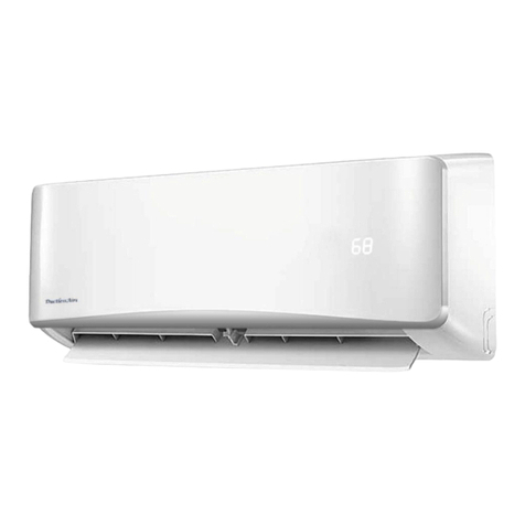
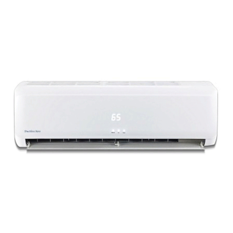
DuctlessAire DA-09 User manual

Service Manual
1
Service Manual
Mini-Splits

Service Manual
2
Contents
1. Applications and features.......................................................................................4
1.1 Computer or Data Server Rooms............................................................................................4
1.2 Commercial, Offices, Shops, Churches etc.......................................................................6
1.3 Residential..........................................................................................................................................7
1.4 Sun Rooms or 4 Season Rooms ..............................................................................................9
1.5 Low Ambient Cooling................................................................................................................10
1.6 Heat Pump........................................................................................................................................15
1.7Sleep function.................................................................................................................................15
1.8Anti-mildewing operation function.....................................................................................15
1.9 Remember function at the time of power failure...........................................15
2. Pre Installation Requirements..............................................................................22
2.1 Unit sized correctly and applied correctly........................................................................22
2.2 Electrical Requirements............................................................................................................22
2.3 Breaker Size....................................................................................................................................22
2.4 Line Set Lengths and Sizes......................................................................................................20
2.5 Indoor Unit Positioning.............................................................................................................21
2.6 Outdoor Unit Positioning..........................................................................................................21
3. Installation Tips.....................................................................................................21
3.1R410A Refrigerant.......................................................................................................................24
3.2Electrical Wiring Connections...............................................................................................25

Service Manual
3
3.3Number of Electrical Interconnect Wires.........................................................................26
3.4Service Valves................................................................................................................................27
3.5 Adding Refrigerant Charge......................................................................................................28
3.6 Condensate Piping........................................................................................................................28
4. Common Technical Problems...............................................................................29
5. Unit Fault Codes....................................................................................................36
6. Maintenance...........................................................................................................45

Service Manual
4
1. Applications and Features
1.1 Computer or Data Server Rooms
Mini-splits are designed to primarily keep people comfortable. That means the typical
range of temperatures for the zone is 70-72 Deg F.
Mini Splits were not specifically designed for cooling server rooms or other data rooms
however due to their size and ease of installation this is a very common application, and
also the #1 Technical Service issue.
But FOLLOWING these guidelines can make for a reliable, profitable installation in this
application.
Sizing
Sizing of the Mini Split to the room is EXTREMELY IMPORTANT.
DuctlessAire recommends a 12,000 Btu/h capacity per 200 to 250 Sq Ft of room
size. Do not exceed this sizing guideline.
Installing large capacity systems in small rooms will lead to short cycling of the
compressor as the supply airflow from the unit to “bounces back” into the return air stream
of the unit
If using the larger capacity units, Supply air is discharged at a velocity of approximately
6ft per second.
With a small room, where the opposite wall to the unit is less than 10ft away the supply air
only circulates for approximately 4 seconds before returning to the unit.
The room temperature sensor is located on the surface of the cooling coil, if the supply air
quickly “bounces back” into the unit, it will satisfy the sensor and the compressor will be
cycled off.
All DuctlessAire mini splits feature continuous fan operation, maintaining circulation
in the room rapidly picking up the warmer return air from the room, causing the return air
sensor

Service Manual
5
to quickly sense a rise in temperature and call for compressor operation.
This leads to short cycling of the unit, poor temperature control and a greatly reduced unit
life span.
Due to this scenario we recommend that you DO NOT install any capacity of Mini Split
in rooms of less than 100 Sq Ft in Size
Unit Location
Ensure that no obstacles to the air flow from the Indoor unit are within 10 feet of the unit,
be especially aware that Computer server units create an airflow baffle and can have the
same effect on airflow to and from the unit as a small room size.
In Computer room application the DuctlessAire Mini Split units must be installed a
MINIMUM of 6ft from the floor so that the airflow from the unit is unimpeded.
Sensible Heat and Humidity
DuctlessAire units are designed to provide an approximate SHR of 0.66. Be aware that
low humidity conditions will further reduce unit performance, requiring either additional
higher fan speeds to be programmed into the unit, or introduction of some latent load into
the room, e.g. Use of a humidifier.
Compressor Run Times
To ensure compressor longevity it is paramount that the compressor run time be longer
than 5 minutes at all times throughout the year. This will allow oil return to the
compressor, and will ensure that the max number of starts per hour is not exceeded.
If the compressor runtime is less than 5 minutes, especially at design ambient temperature
it is very likely that the unit is oversized.
Ambient
The other major issue with Computer or Data rooms is that they are designed to operate

Service Manual
6
365 days 24/7. This means that the Outdoor unit will be exposed to temperature below the
minimum design ambient of 65 DegF
Therefore for cooling below 65 DegF, DuctlessAire insists on the following items to be
installed on the system.
1. ICM 326H Fan Speed controller
2. Crankcase Heater on ALL units
If winter temperature fall below 32 DegF a Wind Baffle on the Coil Inlet and the
Exhaust of the condenser fan is required.
This will isolate the unit from any wind that could cause the unit to over condense,
slugging liquid refrigerant back to the Compressor, which can damage the valve plate,
wash oil from the bearing services and eventually cause the Compressor to fail.
A Wind Baffle will provide cooling operation down to an Ambient of 0 DegF Wind
Baffles are field fabricated, drawings are available on request from DuctlessAire.
1.2 Commercial, Offices, Shops, Churches etc
Sizing
Again Sizing and Location of the Mini Split to the room is EXTREMELY
IMPORTANT.
DuctlessAire recommends a 12,000 Btu/h capacity for each 350 to 450 Sq Ft of the
Room Do not exceed this sizing guideline for the same reason as the computer room
application information
Again DO NOT install DuctlessAire Mini Splits in rooms of less than 100 Sq Ft
Ambient
Check as to the lowest ambient temperature that will be required for cooling, the minimum

Service Manual
7
design temperature for the Outdoor unit is 65 DegF, if cooling is required below that,
down to 32 DegF, DuctlessAire insists on an ICM 326H Fan Speed controller being
installed on the Outdoor unit. On ALL units, a Crankcase Heater should also be installed.
For cooling down to 0 DegF, the use of Wind Baffles is required, per the computer room
application information.
Filters
DuctlessAire Mini Splits, because of the constant operation of the fan require much more
frequent filter cleanings or replacements than the standard “ducted US style” units which
are generally used for commercial buildings. DuctlessAire recommends that the filters are
cleaned every 4 weeks of operation, more frequently in areas subject to dirtier conditions
e.g. Warehouse offices etc.
Condensers located inside the Building
Especially with Warehouse or additional office space the condensers can be installed
inside the building, this provides two specific issues to address:
1. Lower ambient, these units are rated at 95 DegF ambient, if the ambient in the
building does not rise above 80 DegF, we can downsize the unit as it will produce
more capacity and operate more efficiently.
2. Cleaning the condenser coil, use soapy water and keep the condenser coil clean,
put it on the same schedule as the indoor unit filter cleaning.
1.3 Residential
Sizing
Sizing and Location of the Mini Split to the room is still EXTREMELY IMPORTANT.
DuctlessAire recommends a 12,000 Btu/h capacity for each 500 to 600 Sq Ft of the
Room for most applications inside the house.

Service Manual
8
The throw of the 9 or 12,000 Btu/h units is approximately 15 feet, and the 18 or 24,000
Btu/h units have a throw of approximately 25 feet.
Therefore when applying these units in a residential application make sure that the units
are not mounted at the top of the stairs blowing directly onto a wall or inside a niche or cut
out in a room.
Again the temperature sensor is designed to sense the returning air after it has been
supplied to the room, extracted the heat and humidity and then returned to the unit, not
when it has been bounced directly back off a wall or other obstacle.
Ambient
As standard the units are capable of cooling down to an ambient of 65 DegF, which is
sufficient for the majority of residential applications.
Indoor unit Location
For optimum unit operation the High Wall Indoor unit should be mounted a minimum of 6
feet from the floor. A minimum height of 4 feet must be maintained for correct unit
operation. Ensure air flow is never directly straight onto areas where people may sit or
congregate, as the temperature difference between Supply and Return air will be
approximately 35 DegF.
Outdoor unit location
The Outdoor units are designed to operate with extremely low noise levels compared to
the standard US condensing unit, this allows the outdoor units to located in areas closer to
property lines, however when locating the DuctlessAire Outdoor unit,ensure that the
spacing detailed in the Installation manual are observed, and that the maximum line length
and lift restrictions are adhered to.
Garages or FROG’s/Bonus Rooms
DuctlessAire Mini Splits are perfect for adding conditioning to Garages and Bonus
Rooms Use a 400 sq per 12,000 Btu/h sizing guide and as always follow the
location

Service Manual
9
guidelines provided for the Indoor and Outdoor unit.
1.4 Sun Rooms or 4 Season Rooms
Sizing
Sizing and Location of the Mini Split to the room is still EXTREMELY
IMPORTANT. DuctlessAire recommends a 12,000 Btu/h capacity for each 325 to
350 Sq Ft of the Room.
The throw of the 9 or 12,000 Btu/h units is approximately 15 feet, and the 18 or 24,000
Btu/h units have a throw of approximately 25 feet.
Sun Rooms are a great application for DuctlessAire Mini Split units however there are
several items that must be addressed to make the installation a success.
Ambient
Sun Rooms are different in their application as they by definition have a large solar gain
and therefore can require cooling in cold ambient temperatures. Therefore as per
Computer room and Commercial applications it is mandatory to install the ICM 326H low
ambient control and a crankcase heater on the system.
Indoor unit Location
For optimum unit operation the High Wall Indoor unit should be mounted a minimum of 6
feet from the floor. A minimum height of 4 feet must be maintained for correct unit
operation.
Ensure air flow is never directly straight onto areas where people may sit or congregate, as
the temperature difference between Supply and Return air will be approximately 35 DegF.
Heat Pumps
In order to use the Sun Room year round Heat Pumps are the recommended system,

Service Manual
10
however it may be advisable to install some additional source of heat, such as electric
baseboard if the Sun Room is to be used in temperatures below 24 DegF.
Below 24 DegF the air temperature delivered from the unit will be close to body
temperature making it feel uncomfortable, as when the Outdoor temperature falls the
unit capacity and efficiency reduces, together with the unit requiring more frequent defrost
cycles.
This will assist in truly making the Sun Room a room to be enjoyed in comfort all year
round.
1.5 Low Ambient Cooling
As stated in the Computer Room, Commercial and Sun Room application pages -
ALL DuctlessAire models are capable of providing COOLING operation down to an
ambient temperature of 65 DegF.
Therefore to operate in Cooling down to an ambient temperature of 32 DegF, both an
ICM326H Fan Speed Controller, plus a Crankcase Heater, either a Mars #32342 or
Raychem #CCH-1 or 2 bellyband types MUST be installed.
For cooling operation below 32 DegF, and down to a minimum of 0 DegF, DuctlessAire
recommends that Wind Baffles be installed on both the Coil Inlet and Fan Outlet of the
Outdoor unit. Please contact DuctlessAire directly for details of the design requirements
for the Wind Baffles.
We also recommend using these Wind Baffles in applications where the units may be
exposed to prevailing winds blowing though the condenser coils. These winds may cause
the unit to over condense and freeze the indoor unit, or allow liquid refrigerant to be
inadvertently slugged back into the compressor.
Installing the ICM326H Fan Speed Controller
The controller should be located per the instructions provided, it is not weatherproof,
therefore should be mounted inside the compressor compartment of the Outdoor unit.
DuctlessAire Units have Ball Bearing Condenser Fan motors, set both the Hard Start and
cut out speed setting dials to 1/3 off the MINIMUM position.

Service Manual
11
The Temperature sensing probe should be securely attached on or adjacent to a return bend
on the condenser coil that measures 100 DegF in normal operation. In practice this
works out to be the 3rd Return bend down from the top of the coil. Securely strap the probe
to the bend or tube and insulate to ensure accurate temperature sensing.
Wiring
Wiring should be in accordance with the diagrams on the following pages, DO NOT
deviate from the wiring shown, if in doubt please call Technical Support for assistance.
Please note on Heat Pump units the bypass connection must be wired from the Reversing
Valve to the ICM controller to ensure that the Outdoor fan operates at full speed in the
Heat Pump Heating mode.

Service Manual
12
Low Ambient Wiring Cs-26C1A / CS-35C1A
Low Ambient Wiring Cs-51C2A / KF-70GW/GX1a

Service Manual
13

Service Manual
14
Low Ambient Wiring Cs-51H2A / KFR-70GW/GX1a

Service Manual
15
1.6 Heat Pump
DuctlessAire Heat Pump units are NOT fitted with any type of auxiliary heating for back
up heat during periods of time when the outdoor ambient is too cold to allow for full
capacity operation. Basically the colder the air outside, the lower the capacity and supply
air temperature provided by your DuctlessAire Heat Pump.
If the Outdoor Coil temperature is below 14 DegF, Heat Pump operation is stopped and the
unit will shut down, until the coil temperature increases.
Therefore we recommend that the DuctlessAire heat pump should NOT be used as the
primary source of heating where Outdoor temperatures are regularly below 24 DegF for
sustained periods of time.
If a Heat Pump is used in these applications ensure that an additional source of heat
(baseboard electric or hydronic, or other type) be used when the temperature falls below
24 DegF.
Warm Start
In Heat Pump operation the Indoor fan motor will only start operating, when the indoor
coil temperature has reached 86 DegF. Then the fan will start operating in an ultra low
speed mode, increasing in fan speed back to the selected speed on the remote control as
the Indoor coil temperature increases.
When the unit completes Defrost, the warm start feature will be used to allow the coil to
warm up before restarting the Indoor fan. Warm start operation is indicated by a the run
light on the display blinking once.
Heat Pump Heating on the Remote Control
The symbol on the Remote Control for Heat Pump Heating is a little confusing
The symbol that is a SUN is the correct symbol for Heat Pump Heating Press the mode
button until the SUN is displayed, and then selects the desired temperature and fan speed
and the unit will operate in Heat Pump mode.

Service Manual
16
The symbol that looks like a FLAME is actually be a DRIP of water. This mode is the
DRY mode, which is used to cool the room down at the lowest possible fan speed, which
removes the most moisture from the room.
Therefore if your customer complains that his heat pump is not operating in heating, first
check that he has it in the correct mode on the remote control.
Defrost
DuctlessAire units feature “Demand Defrost” which allows the unit to choose when to
enter into defrost, not just every 30, 60 or 90 minutes as most heat pumps
An Outdoor coil temperature sensor is located in the Outdoor unit, it MUST be connected
back to the Indoor PCB, the sensor will assist in determining if defrost is required. (Not
connecting the sensor will result in a fault code –see fault section)
During Defrost the Indoor fan motor will stop so that cold air is not blown into the room.
The Outdoor fan motor will also stop to speed up the defrost process.
After defrost has finished the compressor will stop to equalize pressures. A single blink
of the operating light shows that unit is in defrost.
Defrost Initiation and Termination
Come into the defrosting status state: (only meet one of the following conditions, the
unit will come into the defrosting status)
A After the accumulated running time of the compressor reaches thirty minutes in the
heating mode, if the temperature inspected and measured by the sensor on the outdoor coil
pipe is below 5DegF (programmable data 28#) in continuous one minutes and the
compressor has been continuously working for three minutes, then the system will come
into the defrosting status.
B After the accumulated running time of the compressor reaches forty minutes in the
heating mode, if the temperature inspected and measured by the sensor on the outdoor coil

Service Manual
17
pipe is below 23DegF (programmable data 27#) in one minutes continuously and the
compressor has been continuously working for three minutes, then the system will come
into the defrosting status.
C After the waiting time of the air conditioning is longer than thirty minutes, the unit
will come into the heating mode after been started up. Or it will come into the heating
mode at the first time of powering on. If the temperature of the outdoor coil pipe is below
28.4DegF, then the air condition will firstly come into the defrosting status.
The conditions of exiting the defrosting status: (only meet one of the following
conditions, the unit will exit the defrosting status)
A When the sensor temperature of the outdoor coil pipes is above 59DegF(programmable
data 29#), the unit will exit the defrosting status.
B When the defrosting time is longer than fifteen minutes, the unit will exit the
defrosting status.
Reversing Valve
The reversing or 4 way valve is energized for HEATING in a DuctlessAire unit. If the
unit does not produce heat when in the Heat Pump mode, check for line voltage starting at
the Indoor unit terminal, and follow that voltage out via the interconnecting wire to the
solenoid coil on the valve.
Reversing valve coils are line voltage, again units do not use any 24V AC controls
Over heating protection
When the inspected and measured temperature of the indoor coil Tp1 is higher than
or equal to 145DegF(programmable data 26#), the compressor, outdoor blower will

Service Manual
18
stop operation, the indoor blower will operate according to the set wind speed,
(when the start up condition of the compressor is satisfactory to) the operation will
be restarted up six minutes later, if the temperature of the indoor coil Tp1 is higher
than or equal to 145DegF for the second time within ten minutes after the start up,
all of the output will be closed, and E8 will be displayed on the display panel.
Sleep function
A When the “Sleep”key on the remote controller is pressed down, the air
conditioning will come into the sleep status, the indoor blower will be switched to
the low wind speed operation, when the “Sleep”key is pressed down for the second
time, the sleep will be canceled, the air conditioning will come back to the operation
status the same as the status before the sleep, the indoor blower will still be operating
according to the set wind speed that is set during the sleep. The unit can be shut
down through pressing down the “ON/OFF”key on the remote controller, and the
sleep setting will also be canceled at the same time.
B Pressing down the “Sleep”key on the remote controller to set the sleep operating,
after five seconds, there will be only sleep icon displayed on the display screen or
the operation light and the sleep light are lighting, all of the other icons are closed,
this is the sleep and screen closing status.
a For the colorful screen display: at the time of sleep, only the sleep icon is
displayed, and all of the other icons are closed.
b For the 8LED + LED light display: the operation light and the sleep light are
lighten, all of the other icons are closed. If there is no operation light and the

Service Manual
19
sleep light, then all of the lights will not be lighten.
Annotation: during the sleep operation, if the unit receives the timing time that has
been adjusted, the twinkling of the 8LED on the display screen means that the
status is being changed, if the unit receives that the set temperature has been
adjusted, the 8LED will be lighten, the air conditioning will be adjusted to the
operation status the same as the status before the sleep during the changing
status, it will be closed if there is not any change in five seconds.
C Set the sleep in the cooling mode, it will be Ts+1℃after one hour, it will be Ts+
2℃after two hours, and it will keep the same value from that time on.
D Set the sleep in the heating mode, it will be Ts-1℃after one hour, it will be Ts-
3℃after two hours, it will be Ts-5℃after three hours ,and it will keep the
same value from that time on.
E Set the “sleep”in the dehumidify mode, the unit will keep on the operation
according to the dehumidify mode, but the sleep and screen closing will be
execute.
F Set the “sleep”in the ventilation mode, the set temperature will not be adjusted,
the sleep and screen closing will be execute.
G Set the sleep in the automation mode, no matter which mode the automation mode
come into, then the sleep function will be operated according to the
corresponding mode during the setting of the sleep.
H Under the sleep mode, the wind speed of the indoor blower can be adjusted,
except for the dehumidify mode.

Service Manual
20
I The “sleep”and “turbo”can not be operated at the same time, that is to say there is
no sleep function during the turbo operation, and there is no turbo function in the
sleep status.
Anti- mildewing operation function
If the air conditioning is shut down during the cooling operation under the
cooling,dehumidify or automation mode, then the air conditioning will execute the
anti- mildewing operation function. The compressor and indoor blower will be
operated according to the curve in the start up period that is shown in the following
figure, the indoor blower is in the operation status of low wind speed, the air flap
will be closed thirty seconds after it has been operated according to the original
status, the outdoor blower and the four- way valve are in the closing status.
A:controlled object B: indoor blower C:compressor
D: start up E: shut down F: time
This manual suits for next models
3
Table of contents
Other DuctlessAire Air Conditioner manuals
Popular Air Conditioner manuals by other brands

LG
LG Room air conditioner installation manual

Whirlpool
Whirlpool SPIW409A2WF Instructions for use

Fujitsu
Fujitsu Inverter 9316796003-01 operating manual

Coopers of Stortford
Coopers of Stortford HydroBreeze 11441 Instructions for use

Webasto
Webasto BlueCool Classic Series installation instructions

Panasonic
Panasonic CS-PS9NKP quick guide