dumore 57 Series User manual

DUMORE CORPORATION
Quality is our legacy
®
1030 Veterans Street, Mauston, WI 53948-9314
Telephone 608-847-6420 FAX 1-800-338-6673
884-0263
REV. 11/2019
29696
Printed in USA
TOOL POST GRINDERS
MODEL 8587-210
MODEL 8584-210
MODEL 8588-210
MODEL 8479
SERIES 57
PARTS LIST
AND
OPERATING
INSTRUCTIONS
www.dumoretools.com

INTRODUCTION
Dumore tool post grinders have an international reputation for quality and dependability. Our Series 57 will turn a standard
lathe or other machine tool into a versatile, accurate, internal-external grinder. Cylindrical parts can be machined and then
finished ground in the same set-up. The Series 57 can be mounted on the compound of a lathe in a matter of minutes.
Features include nine spindle speeds and coil spring applying constant belt tension assuring proper alignment. A wide
range of spindles are available for toolroom, maintenance and production line needs.
POLICY STATEMENT
Dumore Corporation is committed to providing products that meet the ever expanding needs of our customers. It is our goal
to be the continuing leader in product quality, safety, and reliability.
TABLE OF CONTENTS
Introduction, Policy Statement Page 2
Safety Instructions Page 3 - 4
Specifications Page 5
Rules for Safe Grinding Page 6 - 7
Mounting Criteria Page 7
Safety Warnings Page 8
Set-Up Instructions Page 9 - 11
Face Grinding Page 12
Internal Grinding Page 12
Wheel Dressing Page 12
Selecting the Proper Wheel Page 12
Selecting the Proper Spindle Page 13 - 15
Grinding Wheel Listing Page 16 - 17
Pulley & Belt Combination Chart Page 18
Maintenance Instructions Page 18
Exploded View Page 19
Parts Listing Page 20 - 22
Mounted Wheel Chart Page 23
Warranty Page 24
Authorized Repair Centers Page 24
READ AND SAVE THESE INSTRUCTIONS!!
2

THE NEED FOR GROUNDING
In the event of a malfunction or breakdown, grounding provides
a path of least resistance for the electric current to reduce the
risk of electric shock. This tool is equipped with an electric cord
having an equipment grounding conductor and a grounding
plug. The plug must be plugged into a matching outlet that is
properly installed and grounded in accordance with all local
codes and ordinances.
s Note: Do not modify the plug provided - if it will not fit the
outlet, have the proper outlet installed by a qualified
electrician.
Improper connection of the equipment-grounding conductor
can result in a risk of electric shock. The conductor with
insulation having an outer surface that is green, with or without
yellow stripes, is the equipment - grounding conductor. If repair
or replacement of the electric cord or plug is necessary, do not
connect the equipment-grounding conductor to a live terminal.
Check with a qualified electrician or serviceman if the grounding
instructions are not completely understood, or if in doubt as to
whether the tool is properly grounded.
Repair or replace damaged or worn cord immediately.
Periodically check the ground circuit of the cord for continuity.
The use of a ground-fault protected receptacles is
recommended.
s WARNING: THIS TOOL SHOULD ONLY BE USED WHERE
POINT OF OPERATION GUARDING DEVICES HAVE BEEN
PROPERLY INSTALLED SO THAT IT IS IMPOSSIBLE FOR
THE OPERATOR’S HANDS OR FINGERS TO REMAIN
WITHIN THE POINT OF OPERATION DURING THE ACTUAL
MACHINE CYCLE.
s WARNING: Read all instructions. When using electric
tools, basic safety precautions should always be used to
reduce the risk of fire, electric shock, and personal injury,
including the following:
1. ALWAYS USE SAFETY GLASSES
(ANSI Z87.1 with side shields or an equivalent).
Polycarbonate lenses have been found to provide better
impact resistance than glass lenses
2. WEAR PROPER APPAREL
No loose clothing, gloves, neckties, rings, bracelets, or
other jewelry to get caught in moving parts. Non slip
footwear is recommended. Wear protective hair covering
to contain long hair.
3. DO NOT USE IN DANGEROUS ENVIRONMENT
Do not use power tools in damp or wet locations, or expose
them to rain. Keep work area well lighted. Do not use tool in
presence of flammable liquids or gases.
4. KEEP WORK AREA CLEAN
Cluttered areas and benches invite accidents.
5. DO NOT OVER-REACH
Keep proper footing and balance at all times.
6. REDUCE THE RISK OF UNINTENTIONAL
STARTING
Make sure switch is in off position before plugging.
7. CHECK DAMAGED PARTS
Check for alignment of moving parts, breakage of parts,
mounting, and any other conditions that affect its
operation. A part that is damaged should be properly
repaired or replaced by an authorized service center
unless otherwise indicated elsewhere in this instructional
manual. DO NOT USE TOOL IF SWITCH DOES NOT
TURN IT ON AND OFF. HAVE DEFECTIVE SWITCHES
REPLACED BY AUTHORIZED SERVICE CENTER.
8. DISCONNECT TOOLS
When not in use, before servicing and when changing
accessories, such as grinding wheels, etc.
9. REMOVE KEYS AND WRENCHES
Form habit of checking to see that keys and adjusting
wrenches are removed from tool before turning it on.
10. MAINTAIN TOOLS WITH CARE
Keep tools sharp and clean for best and safest
performance. Follow instructions for lubricating and
changing accessories. Inspect tool cords daily and if
damaged, have repaired by authorized service facility.
Inspect extension cords before use and replace if
damaged. Keep handles dry, clean, and free of oil and
grease.
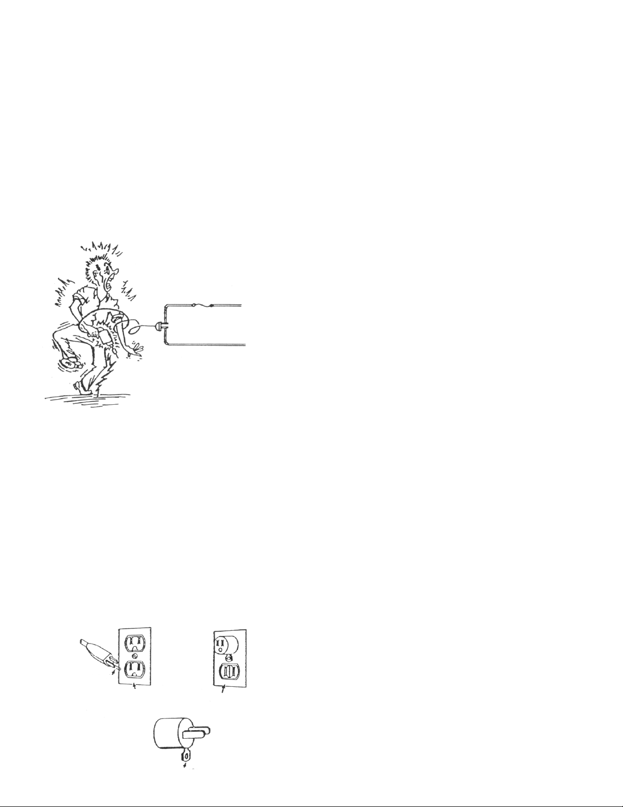
s SAFETY INSTRUCTIONS
FUSE INTACT
HOT LINE
THIS SYSTEM IS DANGEROUS!
Don’t act as a conductor—Make
sure the tool is grounded through
the cord.
GROUNDING
BLADE COVER OF
GROUNDED
OUTLET BOX
GROUNDING MEANS
COVER OF
GROUNDED
OUTLET BOX
3

19. DO NOT ABUSE CORD
Never carry tool by cord or yank it to disconnect from
receptacle. Keep cord from heat, oil and sharp edges.
20. USE RECOMMENDED ACCESSORIES
Consult this manual or any Authorized Dumore Distributor
for recommended accessories. The use of improper
accessories may cause risk of injury to persons.
21. SET-UP
Do initial set-up and adjustment at an empty station. Keep
hands and clothing out of path of tool.
22. LOCKOUT / TAGOUT
Whenever maintenance work is being done on electrical
equipment, the Lockout/Tagout Procedure as required by
OSHA standard
23. SAVE THESE INSTRUCTIONS
s THIS SYMBOL IS USED THROUGH OUT THE
MANUAL TO HIGHLIGHT POTENTIAL DANGERS
11. SECURE WORK
Use clamps, a vise or fixture to hold work. It’s safer than
using your hand and it frees both hands to operate tool.
12. USE RIGHT TOOL
Do not use tools or attachments to do a job it was not
designed for.
13. DO NOT FORCE TOOL
` It will do the job better and safer at the rate for which it was
designed.
14. NEVER LEAVE TOOL RUNNING UNATTENDED,
TURN POWER OFF
Do not leave tool until it comes to a complete stop.
15. KEEP CHILDREN AWAY
All visitors should be kept safe distance from work area.
Do not let visitors contact tool or extension cord.
16. STORE IDLE TOOLS
When not in use, tools, should be in dry, high or locked-up
place out of reach of children.
17. STAY ALERT
Watch what you are doing. Use common sense. Do not
operate tool when you are tired, under medication, or
under the influence of drugs or alcohol.
18. KEEP COVERS IN PLACE AND IN WORKING ORDER
4

SPECIFICATIONS
MODEL 8587-210
Motor: 1/2 HP Universal open type, fan cooled (with intake air
filter)
Power Supply: The Model 8587-210 Grinder is equipped with a
120 Volt Universal Motor. Be sure that the voltage of the power
supply agrees with the voltage shown on the motor nameplate.
Spindles: Interchangeable. Spindles are not included. See
spindle chart on page 14.
Grinding Speeds: 3,750 to 45,000 RPM
Grinding Wheel Capacity: 1/2” to 6” (Varies with quill used)
External Grinding Capacity: To 6” diameter wheels (Varies
with quill used)
Internal Grinding Capacity: 18” deep at diameter of 1-7/8”
(Varies with quill used)
Mounting: T-Bolt
Dimensions:
Center line of spindle to base - 1-1/8”
Center line of spindle to center line of mounting post - 1-3/4”
Weight: Ship Weight: 46 lbs, without spindle.
5
SERIES 57
SPECIFICATIONS
MODEL 8584-210 (w/intake Air Filter)
Motor: 3/4 HP Universal open type, fan cooled ventilation
Power Supply: The Model 8584-210 Grinder is equipped with a
high speed, universal motor which operates on 120 Volt, 60 Hz.
Be sure that the voltage of the power supply agrees with the
voltage shown on the motor nameplate.
Spindles: Interchangeable. Spindles are not included and
must be ordered separately. See spindle chart on page 14.
Grinding Speeds: 3,200 to 42,600 RPM
Grinding Wheel Capacity: 1/2”to 6” (Varies with quill used)
External Grinding Capacity: To 6” diameter wheels (Varies
with quill used)
Internal Grinding Capacity: 18” deep at diameter of 1-7/8”
(Varies with quill used)
Mounting: T-Bolt
Dimensions:
Center line of spindle to base - 1-1/8”
Center line of spindle to center line of mounting post - 1-3/4”
Weight: Ship Weight: 46 lbs, without spindle.
SPECIFICATIONS
MODEL 8588-210
MODEL 8479
Motor:
Model 8588-210 has a 1 HP Universal open type, fan cooled
(with intake air filter). Model 8479 has a 1 HP induction: totally
enclosed, fan cooled.
Power Supply: The Model 8588-210 Grinder is equipped with a
120 volt Universal motor. The Model 8479 Grinder is equipped
with a 220/380-440 volt, 3 Phase, 50-60 Hz. induction motor. Be
sure that the voltage of the power supply agrees with the voltage
shown on the motor nameplate.
Spindles: Interchangeable. Spindles are not included. See
spindle chart on page 14.
Grinding Speeds: Model 8588-210: 3,560 to 47,500 RPM
Model 8479: 3,600 to 32,600 RPM
Grinding Wheel Capacity: 1/2” to 6” (Varies with quill used)
External Grinding Capacity: To 6” diameter wheels (Varies
with quill used)
Internal Grinding Capacity: 18” deep at diameter of 1-7/8”
(Varies with quill used)
Mounting: T-Bolt
Dimensions:
Center line of spindle to base - 1- 1/8”
Center line of spindle to center line of mounting post - 1-3/4”
Weight: 8588-210: Ship Weight: 46 lbs, without spindle.
8479: Ship Weight: 58 lbs, without spindle.

s RULES FOR SAFE GRINDING
1. Always wear Suitable Safety Glasses
(ANSI Type Z87.1 with side shields or an equivalent) Also
wear a face or dust mask if grinding operation is dusty.
2. Always “Ring or Vibration Test” Straight Wheels
Before Use
Sound wheels produce a definite ring when struck lightly
with a non-metallic object - screwdriver handle, etc.
Cracked wheels produce a dull or dead sound. Suspend
the wheel from a hole using a small pin or finger and test
spots about 45 degrees apart around the wheel, see figure
2 below. Never use wheels that do not ring
satisfactorily. Damaged wheels should be replaced
immediately. The wheel hole should be suitably oversize
to assure safety clearance under normal operating heat
and pressure. Certain wheels require vibration testing. See
page 17 for vibration testing.
3. Always Use Proper Wheel Balance
Never exceed the speed on the blotter of a grinding wheel.
Never mount a wheel on a grinder without checking pulley
combinations to make sure the speed is safe for the wheel
diameter and type. Blotters should be large enough to
cushion flange pressure for the entire bearing surface of
the flange.
4. Only Use Flanges Furnished With The Grinder
Flanges must match on straight wheels. If flanges are not
the same diameter, the wheel is under a bending stress that
is likely to cause fracture. If they are not properly relieved,
pressure is concentrated on the sides of the wheel at the
hole, a condition which sets up tremendous stresses and
which may cause the wheel to break.
• Both flanges, between which a wheel is mounted,
should be the same diameter and properly relieved.
The minimum size of flanges for straight wheels should
be at least one-third of the diameter of the new wheel.
• Straight wheels must have an outer flange. Both
flanges serve a useful purpose, and neither should be
omitted. Flanges should be checked for distortion or
abrasion.
• The outer flanges must not be reversed. The raised
bearing surface (relieved side) must be against the
wheel. Otherwise, unequal bearing surfaces produce
the same effect as unmatched flanges.
• A flat washer, a steel punching, or any other type of
filler material must not be used in place of a properly
relieved flange as the bending stress imposed upon
the wheel may cause it to fracture (see figure 1).
5. Always Use A Wheel Cover on External Grinding Jobs
The wheel cover will minimize the possibility of accidental
contact with the wheel by the operator and will help confine
grinding dust and grit. It will also aid in protecting, but does
not provide total protection, for the operator should the
wheel explode. Damaged wheel guards should be
replaced immediately.
6. Do Not Over Tighten Wheel Nut. Over Tightening Of
The Wheel Nut May Spring The Flange.
A sprung flange can cause stress concentrations which
may break the wheel. Under tightening of the spindle end
nut can permit wheel slippage which may result in
breakage.
• Torque wrenches are not applicable to tightening
single end nuts because normal thread wear cause a
continual change in the relationship between torque
applied to the nut and flange pressure on the wheel.
• The direction of the thread shall be in such relation to
the direction of rotation that the nut will tend to tighten
as the spindle revolves. The following rule will assist in
determining the proper relationship: “To remove the
nut it must be turned in the direction that the
spindle revolves when the wheel is in operation”.
All threads of the wheel nut should engage when tight.
6
CORRECT INCORRECT
Figure 1
CORRECT AND INCORRECT METHOD OF
MOUNTING STRAIGHT WHEELS
WHEEL BLOTTERS
FLANGE RECESS
TOWARD WHEEL
WHEEL NUT THREADS
FULLY ENGAGED
SPINDLE
FLANGES UNIFORM IN
DIAMETER AND
BEARING SURFACE AREA
FLANGE NOT RECESSED
WHEEL NUT THREADS
NOT FULLY ENGAGED
NO WHEEL BLOTTERS
FLANGE SPRUNG FROM
EXCESSIVE WHEEL
NUT TORQUE
SPINDLE
ONE FLANGE LARGER
IN DIAMETER THAN
THE OTHER
Figure 2

7. Stand At One Side
When starting and during the first minute of run time.
8. Run At Full Operating Speed
With wheel cover in place for at least one minute before
applying work.
9. Always Remove Pulleys, Wheel And Adjusting
Wrenches From the Grinder When Not In Use.
This compels every operator to make the speed selection
for the wheel diameter they are using.
10. Always Store Wheels Safely
Store them where they are protected from jarring, falling, or
blows from other objects. Do not store wheel in the grinding
case. Protect wheels from high humidity and freezing
temperatures.
We Recommend That Dumore Wheels Be Used With
Dumore Grinders.
s This Symbol Is Used Throughout The Manual To
Highlight Potential Dangers
MOUNTING CRITERIA
The Series 57 Tool Post Grinder is designed for use on lathes
with a 9” to 20” swing. All tool post grinding is done with the
grinding spindle center adjustment to the exact height of the
work center. Therefore, the distance from the top of the
compound to the center line of the lathe spindle, “X,” (Figure 14)
must always be equal to or greater than the distance from the
base of a grinder frame to the center of the spindle (commonly
referred to as the minimum mounting distance). If this condition
does not exist, the grinder will not fit the lathe, because the
grinding spindle cannot be set at work center. If the grinder is
being used on one lathe specifically, a good time-saving idea is
to make a metal spacer plate to fit between the mounting post
base and the base of the grinder frame so the tool automatically
lines up with the work center.
Figure 2
7

8
WARNING
PART #
MAX RPM
DUMORE CORPORATION
®
1030 Veterans Street
Mauston, WI 53948
NEVER EXCEED MAXIMUM RPM
AS LISTED ON WHEEL BLOTTER.
NEVER EXCEED MAXIMUM WHEEL
SIZE FOR SPINDLE OR GRINDER
NEVER RUN WHEELS WITHOUT RING
TESTING OR VIBRATION TESTING
BEFORE EVERY USAGE.
NEVER RUN GRINDER WITHOUT
BELT GUARD IN PLACE
NEVER RUN GRINDER PRIOR TO
CHECKING PULLEY COMBINATION FOR
RPM LESS THAN MAXIMUM RPM LISTED
ON BLOTTER
sVIOLATION OF THESE AND OTHER SAFETY INSTRUCTIONS AS LISTED IN THIS MANUAL
CAUSE RISK OF SERIOUS PERSONAL INJURY.
NEVER DO EXTERNAL
GRINDING WITHOUT
WHEEL GUARD ATTACHED.

9
Figure 6
Figure 5
Figure 4
Figure 3
Setting Up On A Lathe
Before setting the grinder up on lathe, mount the workpiece either
in a chuck, collet or between centers. The Series 57 Tool Post
Grinder is designed to fit in the T-slot of a lathe compound.
SET UP INSTRUCTIONS
1. Remove the mounting post from the grinder by loosening
the lock nut on the right side of the frame and pulling the post
free. Insert the T-bolt of the mounting post into the T-slot of
the lathe compound and tighten nut at the top as illustrated
in Figure 3.
2. After the mounting post is tightened, set the lathe
compound at any angle listed on the Chart, Figure 7 on
page 10. The starred 60° angles setting seems to be ideal
as the feed is set at .001”, and the actual cut into the work is
.0005”, while the reduction in the diameter of the workpiece
is .0010”. The gradations on a lathe compound dial are in
thousands, and your work will often call for accuracies of
tenths of thousands. The chart will be helpful in determining
how much stock is being removed, the actual cut, and
approximately what reduction is being made in the diameter
of the work.
3. Slip the grinder onto the mounting post and tighten the lock
nut, see Figure 4.
4. Loosen the two screws on the front of the grinder and insert
the grinding spindle into the grinder with the strip pin on the
grinding spindle engaged in the slot in the grinder. A
screwdriver may be used to temporarily expand the slotted
frame while inserting the spindle. Tighten the two screws on
the front of the grinder.
5. Loosen the lock nut and position the tool so that the spindle
is parallel with the workpiece. Set the center line of the
spindle at the center line of the workpiece and tighten the
lock nut. the tail stock center can be used to center the
spindle accurately.
6. Select the proper pulleys for the size of the grinding wheel
which is to be used and install the pulleys on the motor and
grinding spindle as shown in Figure 5. The proper pulley
combination is shown on the speed chart which is fixed on
the motor or belt guards. Check the speed chart each time
for proper pulley recommendations for each wheel size.
s WARNING: DO NOT EXCEED WHEEL SPEED
RECOMMENDATIONS, OR THE WHEEL COULD
EXPLODE.
s Caution: Do not plug grinder into the power source
until the grinder is completely set up and ready to grind.
The wheel cover is assembled to the grinder by slipping it over the
grinding spindle and tightening the screw as illustrated in Figure
6. First mount the wheel guard to the spindle. Next mount the
wheel flanges and proper wheel to the spindle. And lastly
assemble the wheel guard cover.
s WARNING: DO NOT EXCEED MAXIMUM RECOMMENDED
WHEEL SPEEDS AS MARKED ON EACH GRINDING WHEEL.
RING TEST EACH WHEEL FOR CRACKS PRIOR TO
ASSEMBLY ON THE SPINDLE. OBSERVE CAREFUL
HANDLING AND STORAGE OF GRINDING WHEELS. RUN AT
FULL OPERATING SPEED WITH WHEEL COVER IN PLACE
FOR AT LEAST ONE MINUTE BEFORE APPLYING WORK.
DURING THIS TIME, AND PARTICULARLY WHEN STARTING,
THE OPERATOR SHOULD STAND AT ONE SIDE.

10
Figure 10
NOTE: Before mounting the wheel, make certain that it is sound
and free of fractures; and it is equipped with proper wheel
blotters. This is done by ring testing the wheel to make
certain that it has not been damaged from improper
handling or improper storage. To do this tap the wheel
gently with a light non-metallic implement such as the
handle of a screwdriver or a rawhide mallet. (See “Rules for
Safe Grinding”). If the wheel sounds cracked or dead it
should not be used and should be thrown away.
7. Tap the wheel about 45° each side of the vertical center line,
and about 1” or 2” from the periphery. Rotate the wheel 45°
and repeat the test. A sound and undamaged wheel will give
a clear metallic tone or ring. If cracked, there will be a dead
sound - not a clear ring. The wheel can be suspended from
the hole by a small pin or finger. This test should be made
prior to mounting a new or used wheel, or if damage is
suspected.
8. Mount the wheel between wheel collars on the grinding
spindle. The relieved side of the collar should be towards
the grinding wheel on both sides. (See “Rules For Safe
Grinding”). With one wheel collar on each side of the wheel,
tighten the wheel and pulley nut. Do not tighten this
spindle nut, since this may cause excessive stresses
on the grinding wheel. A moderate tightness will suffice.
s WARNING: ALWAYS USE THE WHEEL COVER ON
EXTERNAL GRINDING OPERATIONS.
s NOTE: THE WHEEL COVER WILL MINIMIZE THE
POSSIBILITY OF ACCIDENTAL CONTACT WITH THE
WHEEL BY THE OPERATOR AND WILL CONFINE
GRINDING DUST AND GRIT. IT WILL ALSO AID IN
PROTECTING, BUT DOES NOT PROVIDE TOTAL
PROTECTION FOR THE OPERATOR, SHOULD THE
WHEEL EXPLODE.
9. The Series 57 Tool Post Grinder has automatic belt
adjustment by means of a tension spring. Since the motor
pivots on a tension shaft, the belt can be installed by
pushing the motor forward and slipping the belt over the
pulleys. By releasing the motor, the belt automatically
becomes taut. Attach belt cover hanger to frame and add
belt cover as shown in Figure 8.
10. At this point the grinder has not been plugged into the power
source. Make certain the switch is in the “OFF” position.
Spin the wheel mounted on the grinding spindle by hand to
make certain everything is free and in clearance.
s Check to make sure the supply voltage is correct. A 115 Volt
grinder plugged into a 230 VOLT socket would substantially
over-speed the motor and grinding spindle and could result
in an excessive speed which would cause the wheel to
break. After verifying the voltage, plug the cord, into a
suitable grounded outlet.
Figure 9
Figure 8
Angle Setting of
Lathe Compound
Feed On
Compound in Inches
Actual Cut Taken
Into The Work
Reduction in
Work Diameter
30°
45°
*60°
70°
75°
80°
84°
.001
.001
*.001
.001
.001
.001
.001
.00087
.00071
*.00050
.00034
.00026
.00017
.00010
.00173
.00141
*.00100
.00068
.00052
.00035
.00021
Figure 7

11
Figure 11
Figure 12
Figure 13
10. Before either diamond dressing the wheel or before
applying it to the work, turn the unit on and stand clear (from
in line with the grinding wheel) and allow the grinding wheel
to run at full operating speed for at least one minute.
11. Dress the wheel to make the grinding face parallel with the
workpiece. This is done by clamping the diamond dresser to
the workpiece as illustrated in Figure 9. This is for external
grinding. Dressing for internal grinding is described later.
Turn the grinder switch on and make a very light pass over
the diamond nib using the hand wheel traverse. Make
several passes back and forth over the nib without resetting
depth dial. Since wheels are costly and have to be replaced
as they wear down, always take a very light pass over the
diamond nib. For precision grinding of all kinds, truing is
necessary at intervals in order to insure accuracy of results.
s WARNING: GRINDING GENERATES DUST.
Most of the dusts generated when grinding are from the material
being ground. Excessive dust inhalation may affect the breathing
function. To avoid breathing impairment always employ dust
controls and/or protective measures appropriate to the materials
being ground. See Federal Hazard Communication Standard
29CRF, 1910.1200.
12. After removing the dresser, set the work speed of the lathe
for approximately 50 RPM which is normal operating speed
and ideal for most grinding conditions. Although this speed
is suitable for many operations, the work RPM can be set to
meet any requirements. Advance grinder slowly until wheel
barely touches surface to be ground.
13. Upon wheel contact with the workpiece, increase the feed
on the lathe compound to .001” or any suitable in feed
selected and engage the traverse mechanism. When
grinding to very close tolerances, redress the wheel as
outlined above before making the final grind over the stock.
Allow the wheel to spark out on this final grind by taking
several passes back and forth over the piece, using the
hand wheel to traverse carriage.
s CAUTION: Never operate the grinder without wearing
proper safety glasses or goggles. (ANSI TYPE Z78.1
with side shields or an equivalent).
14. Occasionally, when grinding the full length of a piece
mounted between lathe centers, the grinder must be
positioned to allow pulley end to clear tail stock. To do this,
loosen mounting post screw, and turn wheel end in toward
workpiece sufficiently to clear tail stock with pulley. Lock
grinder in position and dress wheel face parallel with
workpiece.
STRAIGHT STRAIGHT
CUP OR
RECESSED
FLARING
CUP
FACE
GRINDING
GRINDING FACE

12
FACE GRINDING
The best method of face grinding is to rotate the Tool Post Grinder
so the spindle is 90° to the lathe center and move the wheel into
position using the compound. On many lathes, however,
compound travel is insufficient, and the following method is
suggested:
Set Up Instructions:
1. Clamp the diamond dresser onto the workpiece or a piece of
stock chucked in the lathe, with the diamond nib facing the
operator.
2. Remove the nib by loosening the locking set screw and
insert the diamond into the right side hole so that it extends
about 1/8” beyond the holder and faces the tailstock as
illustrated in Figure 12 on page 11.
3. Rotate the Tool Post Grinder sufficiently to allow the corner
of the wheel to traverse the full width of the face to be ground
using the compound travel. Bevel the corner of the wheels
as shown in Figure 13 on page 11.
NOTE: The grinding operation will determine the
amount of bevel required. A small beveled face will
break down faster that a wide face and consequently
will require redressing more often.
INTERNAL GRINDING
To grind internally, remove the wheel cover, grinding wheel,
collars, and grinding spindle, and insert an internal grinding
spindle, the selection of which is determined by the depth of the
hole to be ground. For more information on internal grinding see,
“Selecting the Proper Grinding Spindle.”
A wheel from 2/3 to 3/4 the diameter of the hole to be ground is
recommended. However NEVER exceed the maximum
recommended wheel size for the spindle as specified in the chart
on page 14. Check the speed chart on the grinder for the proper
pulley combination and assemble to the motor shaft and grinding
spindle.
s WARNING: ALWAYS POSITION THE WHEEL INSIDE THE
WORKPIECE BEFORE TURNING THE GRINDER ON.
DRESSING A WHEEL - INTERNAL GRINDING
Set Up Instructions:
1. To dress a wheel for internal grinding, clamp the diamond
dresser onto the workpiece or a piece of stocked chucked in
the lathe. The diamond will normally face away from the
operator toward the back of the lathe as illustrated in Figure
10 on page 10.
2. With the grinder running, make several very light passes
over the nib using the hand wheel to traverse. You now have
dressed the wheel so that the face nearest you will be
parallel to the work. Therefore, this face should contact the
workpiece when grinding internally as shown in Figure 11 on
page 11.
NOTE: The side on which the wheel is dressed is always
the contact face.
SELECTING THE PROPER WHEEL
Probably no other single factor is more important to achieving
good grinding results than the selection of a proper wheel. An
ideal wheel is one in which the bond wears away as fast as the
wheel grains are dulled. If the grains dull or wear down faster than
the bond, the wheel is too hard, and it will glaze. If the bond wears
away before the grain, the wheel is too soft, and it will load.
These conditions can be overcome to a certain extent by the
speed adjustment. If the wheel appears too hard, increase the
work speed. If the wheel appears too soft, increase the wheel
speed (within RPM specifications for the wheel). However, the
better solution to the problem is the selection of the proper wheel
for the job.
s IMPORTANT: NEVER INCREASE THE WHEEL SPEED OVER
THE MAXIMUM SAFE SPEED OF THE WHEEL.
The grain size and grit of the wheel generally determines the type
of finish to be obtained. A course wheel is desirable for rapid stock
removal. The grains deeply anchored in the bond allow greater
depth of cut. Also, the greater porosity of a coarse wheel assures
a cool cut. While an experienced operator can get a reasonably
fine finish with a coarse wheel, a fine finish is easier with a finer
grained wheel. On finishing grinds allow the wheel to cut freely
with a minimum feed. Heavy feed or pressure on finish grinds may
cause over heating and possibly work distortion.
s IMPORTANT: ALWAYS USE DUMORE BALANCED WHEELS
The selection of a balanced wheel is essential to precision
grinding. Balanced wheels facilitate grinding to precision
tolerances and in many instances prevent unnecessary service
costs. Always use Dumore wheels.
All grinding wheels are breakable; therefore care should be
exercised in handling and storage to prevent damage. Handle
wheels carefully to prevent dropping or bumping. Inorganic
bonded wheels, such as vitrified, silicate and magnesite are more
brittle than organic bonds (resinoid, shellac and rubber) and are
more readily broken by handling, shock or impact.
STORAGE
Wheels can be damaged by high humidity and/or freezing
temperatures and should be stored in areas not subject to
extremes of temperature and humidity. Storage should provide
protection against damage.

13
When selecting a toolpost grinder which uses interchangeable
spindles, care should be taken to choose the spindle which most
closely fits the user’s application. The spindle selected will
determine the grinding wheel size and RPM which can safely be
used (refer to the chart). The first step in selecting a spindle is to
identify those available for each grinder series. The following
chart provides information on all the currently available spindles
for the Series 57. For OD/external grinding choose an external
spindle or the insert spindle with the appropriate inserts. For
ID/internal grinding choose an internal spindle or the insert
spindle with the appropriate inserts.
For internal grinding, choose the spindle that provides the most
rigid set-up. This means that whenever possible a three bearing
spindle should be used to eliminate vibration and chatter. Also
when possible, use the shortest spindle or spindle insert that will
grind the hole. When internal grinding the wheel selected should
be about 2/3 the diameter of the hole to be ground. Knowing this,
remember that the spindle selected will determine which
diameter wheels are available for that spindle.
If your grinding applications require versatility, the 802-0024
insert spindle should be considered. With the spindle the user
can purchase spindle inserts which allow for external grinding.
Refer now to the listing of spindle inserts on the following page.
The 423-0004 insert allows the user to do external grinding.
Using the 423-0015 collet type insert with the 802-0024 allows
the user to employ mounted wheels with a 1/8” or 1/4” shank for
small internal grinding applications. Refer to the appropriate
columns for each spindle or insert for
• minimum internal grinding diameter
• maximum internal grinding depth
• maximum grinding wheel size and RPM
• appropriate wheel bore size
Also note that a selection of general purpose grinding wheels
come with each spindle and spindle insert.
SELECTING THE PROPER SPINDLE

14
MAX INTERNAL
GRINDING DEPTH
MAXI- MIN. HOLES HOLES
MUM MAXI- INT. SMALLER LARGER WEIGHTS
RECOM- MUM GRIND THAN THAN
CATALOG WHEEL MENDED WHEEL -ING QUILL QUILL EQUIPMENT NET SHIP
NUMBER A B C D E F G H J X BORE SPEED SIZE DM DM DM INCLUDED LBS. LBS.
EXTERNAL SPINDLES
1 WHEEL COLLAR, 3 GENERAL
805-0064 12.80 9.61 3.18 1.750 — 1-w-20RH 1-w-20RH — 1.75 — .500 15000 6X1 — — — PURPOSE WHEELS-774-0103 6.25 10
774-0019, 774-0126
805-0066 12.80 9.71 3.53 1.750 — 1-w-20RH 1-w-20RH — — — 1.250 15,000 — — — — 2 BALANCED 7 10
+WHEEL BORE 11-r 5” WHEEL COLLARS
INSERT SPINDLE
802-0024 11.00 9.57 — 1.750 — 1-w-20RH — — — — SEE SPINDLE INSERTS 4.5 6.5
INSERTS FOR INSERT SPINDLE
2 WHEEL COLLARS, 3 GENERAL
423-0006 — — 5.46 — 2.15 — .368 .605 — 1-r-28RH .250 32500 1 1-w X 5-i .56 2.25 — PURPOSE WHEELS-774-0010 .25 .5
(ID) 774-0119, 774-0029
2WHEEL COLLARS
423-0008 — — 6.66 — 3.41 — .250 .605 — 5-40RH .125 25000 1 X 1-i .56 3.56 — 2 GENERAL PURPOSE WHEELS .25 .5
(ID) 774-0005, 774-0018
423-0010 — — 7.71 — 4.46 — .250 .605 — 5-40RH .125 15000 1 X 1-i .56 4.56 — .25 .5
(ID)
2 WHEEL COLLARS
423-0012 — — 8.71 — 5.46 — .250 .605 — 5-40RH .125 15000 1 X 1-i .56 5.56 — 2 GENERAL PURPOSE WHEELS .25 .5
(ID) 774-0005, 774-0018
423-0013 — — 9.71 — 6.46 — .250 .605 — 5-40RH .125 15000 1 X 1-i .56 6.56 — .25 .5
(ID)
1 EACH 1-i” AND 1-r”
423-0015 — — 4.64 — 1.48 — — .680 — — 1-i & 1-r 42500 3-r .12 — — PRECISION COLLETS .25 .5
(MOUNTED WHEELS) SHANKS 4 ASSORTED MNTD WHEELS
2 WHEEL COLLARS, 3 GENERAL
423-0004 — — 3.87 — .52 — 3-i - 24RH .375 — — .375 15000 5 X 3-i — — — PURPOSE WHEELS - 774-0078 2 2.5
(OD) 774-0098, 774-0110
3-BEARING INTERNAL SPINDLE
2 WHEEL COLLARS
794-0058 20.82 9.45 12.97 1.750 9.44 1-w-20RH 3-i - 24RH 1.50 1.01 — .375 15000 2 1-w X 3-i 1.62 9 12.0 2 GENERAL PURPOSE WHEELS 10 12.5
774-0053, 774-0065
2 WHEEL COLLARS
794-0059 26.82 9.45 18.97 1.750 15.19 1-w-20RH 3-i - 24RH 1.50 1.01 — .375 15000 2 1-w X 3-i 1.62 15 18.0 2 GENERAL PURPOSE WHEELS 12 16
774-0053, 774-0065
}
EXTERNAL
INSERT SPINDLE ID INSERT
3-BEARING
INTERNAL
COLLET TYPE
MOUNTED
WHEEL
INSERT
OD INSERT

15
7 INTERCHANGEABLE SPINDLE INSERTS
(Must be used with 802-0024 Insert Spindle)
MOUNTED - WHEEL TYPE INSERT SPINDLE
Part No. 423-0015
Part No. 423-0008
Maximum recommended speed: 42,500 RPM
Complete with chuck, one each 1/8” and 1/4” precision collet
and our assorted mounted wheels. For internal grinding small
holes with mounted wheels.
Maximum recommended speed: 25,000 RPM
Complete with two balanced wheel collars and three general
purpose balanced wheels. For internal grinding down to 5/8”
diameter and 3” deep.
EXTERNAL TYPE INSERT SPINDLE
Part No. 423-0004
Maximum recommended speed: 15,000 RPM
Complete with two balanced wheel collars and three general
purpose balanced wheels. For external grinding with wheels up
to 5” in diameter.
INTERNAL TYPE INSERT SPINDLE
Part No. 423-0006
Maximum recommended speed: 32,500 RPM
Complete with two balanced wheel collars and general purpose
wheels. For internal grinding down to 5/8” diameter and 1-5/8”
deep.
Part No. 423-0010
Maximum recommended speed: 15,000 RPM
Complete with two balanced wheel collars and three general
purpose balanced wheels. For internal grinding down to 5/8”
diameter and 4” deep.
Part No. 423-0012
Maximum recommended speed: 15,000 RPM
Complete with two balanced wheel collars and three general
purpose balanced wheels. For internal grinding down to 5/8”
diameter and 5” deep.
Part No. 423-0013
Maximum recommended speed: 15,000 RPM
Complete with two balanced wheel collars and three general
purpose balanced wheels. For internal grinding down to 5/8”
diameter and 6” deep.

16
Wheels can be damaged by high humidity and/or freezing temperatures and should be stored in areas not subject to extremes of
temperature and humidity. Storage should provide protection against damage.
Dumore wheels are available in six types for grinding the
various types of materials encountered in the majority of
grinding applications. Wheels are aluminum oxide except those
with the symbol * preceding the catalog number which are
silicon carbide. Dimensions of Dumore wheels appear after the
wheels code number in the following order: wheel diameter,
wheel thickness, and hole diameter. For example “774-0008, 60
(1) 3-r x 1-r x .125 is a general-purpose wheel with a diameter of
3-r”, thickness of 1-r” and hole diameter of .125”. Where wheel is
recessed, diameter of recess is given first by the depth of the
recess.
EXPLANATION OF THE CODE IS AS FOLLOWS:
1. General-purpose wheel, for steels of hardness up to
Rockwell C-45.
2. For cast iron, brass and other non-ferrous metals.
3. For stainless steels and steels of Rockwell C-45 to C-60
and all stainless steel based plasma spray coatings.
4. For steels of Rockwell C-60 and higher.
5. For hard and soft rubber rolls.
6. For Grinding Carbide
GRINDING WHEELS
Part No. Code Description Grit Color
UNDER ONE INCH DIAMETER
774-0189 3 1-w x 1-r x .125 60 OW
recessed 1-r x 1-i
774-0005 1 5-i x 1-r x .125 60 GY
recessed 1-r x 1-i
774-0194 4 5-i x 1-r x .125 90 WH
recessed 1-r x 1-i
774-0008 1 3-r x 1-r x .125 60 GY
recessed 1-r x 1-i
774-0010 1 3-r x 1-w x .250 46 GY
774-0190 3 3-r x 3-r x .250 60 OW
*774-0013 2 7-i x 1-r x .125 46 BU
recessed 1-r x 1-i
774-0014 3 7-i x 1-r x .250 60 WH
recessed 1-r x 1-i
ONE INCH DIAMETER
774-0018 1 1 x 1-r x .125 60 GY
recessed 1-r x 1-i
774-0019 1 1 x 1-r x .250 46 GY
774-0191 3 1 x 1-r x .250 60 OW
774-0195 4 1 x 1-r x .250 90 WH
774-0021 1 1 x 1 x .250 46 GY
recessed 1-w x 3-i
BETWEEN ONE AND TWO INCH DIAMETER
774-0023 1&3 1-1-r x 1-r x .250 54 WH
774-0024 1 1-1-r x 1-r x .250 46 GY
774-0029 1 1-1-w x 1-r x .250 46 GY
774-0196 4 1-1-w x 1-r x .250 80 WH
Part No. Code Description Grit Color
BETWEEN ONE AND TWO DIAMETER (Continued)
774-0180 1&3 1-1-w x 3-i x .375 46 WH
774-0031 1 1-1-w x 1-w x .25 46 GY
recessed 5-i x 1-r
774-0033 3 1-1-w x 1-w x .250 60 WH
recessed 5-i x 1-r
774-0197 4 1-1-w x 1-w x .250 80 WH
recessed 5-i x 1-r
774-0034 1 1-1-w x 1 x .250 46 GY
recessed 5-i x 3-i
TWO INCH DIAMETER
774-0040 1 2 x 1-r x .250 54 GY
774-0041 1 2 x 1-r x .250 80 RD
*774-0042 2 2 x 1-r x .250 46 BU
774-0043 3 2 x 1-r x .250 60 WH
774-0198 4 2 x 1-r x .250 80 OW
774-0045 1&3 2 x 3-i x .250 54 GY
774-0167 2 x 3-i x .250 80 WH/RD
(Combination Wheel)
*774-0046 1 2 x 3-i x .375 46 BK
774-0047 1 2 x 3-i x .375 46 BU
774-0049 3 2 1-w x .375 46 WH
774-0050 1 2 x 1-w x .375 54 GY
*774-0051 2 2 x 1-w x .375 46 BU
774-0052 3 2 x 1-w x .375 46 WH
774-0053 1 2 x 1 x .375 46 GY
recessed 1-1-r x 1-w
TWO AND ONE-HALF DIAMETER
774-0061 1 2-1-w x 1-r x .250 46 GY

17
Part No. Code Description Grit Color
TWO AND ONE-HALF DIAMETER (Continued)
774-0065 1 2-1-w x 3-i x .375 46 BU
774-0192 3 2-1-w x 3-i x .375 60 OW
774-0199 4 2-1-w x 3-i x .375 80 OW
774-0066 1 2-1-w x 1-w x .500 46 GY
774-0193 3 2-1-w x 1-w x .500 60 OW
774-0068 1 2-1-w x 1 x .375 46 GY
recessed 1-3-r x 1-w
THREE INCH DIAMETER
774-0073 1 3 x 3-i x .375 46 BU
*774-0074 2 3 x 3-i x .375 46 BU
774-0075 3 3 x 3-i x .375 46 WH
774-0200 4 3 x 3-i x .375 80 OW
*774-0217 5 3 x 3-i x .375 36 BK
774-0080 3 3 x 1-w x .375 46 WH
774-0213 1 3 x 1-w x .500 46 BU
774-0083 1 3 x 3-r x .500 46 BU
774-0086 1 3 x 1 x .375 46 GY
recessed 2 x 1-w
774-0078 1 3 x 1-w x .375 46 BU
Part No. Code Description Grit Color
FOUR INCH DIAMETER
774-0201 4 4 x 3-i x .375 80 OW
774-0098 1 4 x 1-w x .375 46 GY
774-0100 3 4 x 1-w x .375 46 WH
774-0103 1 4 x 1-w x .500 46 GY
774-0105 3 4 x 1-w x .500 46 WH
774-0202 4 4 x 1-w x .500 80 OW
FIVE INCH DIAMETER
774-0110 1 5 x 3-i x .375 46 GY
774-0111 1 5 x 1-w x .375 46 BU
774-0113 3 5 x 1-w x .375 60 WH
774-0203 4 5 x 1-w x .375 80 OW
774-0117 1 5 x 1-w x .500 46 BU
*774-0118 2 5 x 1-w x .500 46 BU
774-0119 3 5 x 1-w x .500 60 WH
774-0122 1 5 x 3-r x .500 46 BU
774-0204 4 5 x 1-w x .500 80 OW
SIX INCH DIAMETER
774-0126 1 6 x 1-w x .500 46 BU
774-0127 2 6 x 1-w x .500 46 BU
774-0128 3 6 x 1-w x .500 60 WH
774-0205 4 6 x 1-w x .500 90 OW
*774-0216 5 6 x 1-w x .500 36 BK
* Due to the bonding agent, these wheels cannot be ring tested and must be vibration tested only.
VIBRATION TEST
The vibration test is based on the way that loose sand or similar material is distributed on the side of a wheel when the wheel is
vibrating.
To perform the vibration test, an abrasive wheel is set on a test fixture in the horizontal position and coated with a thin layer of fine,
dry sand. The wheel is vibrated gently. As the wheel vibrates, the sand granules respond to the vibration energy. If the wheel is
cracked, the granules move away from the crack, if the wheel is sound the granules will continue to be uniformly distributed over the
entire surface of the wheel.
s IMPORTANT: THIS TEST SHOULD INCLUDE AN OBSERVATION ON BOTH SIDES OF THE WHEEL.
COLOR CODE CHART
BU......................................Blue
BK ......................................Black
GY .....................................Gray
GR .....................................Green
OW ....................................Off White
RD .....................................Red
WH.....................................White

Pulley On
Motor
18
PULLEY AND BELT COMBINATION CHARTS
MODEL 8479 (57-042)
26”
26”
26”
22”
26”
26”
19”
19”
Belt
Length
Max.
Wheel
Idling
Spindle
Speed
Pulley On
Spindle
Belt
Number
3/4”
1”
1-1/2”
2”
3”
4”
5”
6”
32,600
22,650
14,000
10,750
7,150
5,500
4,625
3,600
Spindle
No. 0.75
No. 1
No. 1
No. 2
No. 2
No. 0.75
No. 1
No. 5
No. 5
No. 4
No. 3
No. 4
No. 3
No. 1
No. 1
429-0088
429-0088
429-0088
429-0086
429-0088
429-0088
429-0085
429-0085
Pulley On
Motor
MODEL 8584-210 (57-031)
22”
19”
22”
19”
22”
22”
22”
22”
22”
Belt
Length
Max.
Wheel
Idling
Spindle
Speed
Pulley On
Spindle
Belt
Number
1/2”
3/4”
1”
1-1/2”
2”
3”
4”
5”
6”
42,600
27,900
23,400
12,250
10,600
7,000
5,375
4,150
3,200
No. 1.2
No. 1
No. 2
No. 1.2
No. 3
No. 3
No. 3
No. 3
No. 4
No. 4
No. 2
No. 3
No. 1
No. 2
No. 1.2
No. 1
No. 0.75
No.0 .75
429-0086
429-0085
429-0086
429-0085
429-0086
429-0086
429-0086
429-0086
429-0086
LUBRICATION
The motor requires no lubrication, since it is equipped with
grease-sealed bearing.
GRINDING SPINDLES
Dumore grinding spindles are equipped with ball bearings
packed with grease, and require no lubrication. They can be
operated in any position.
All Dumore precision grinding spindles are quipped with water
and dust throwers. When used for wet grinding start the spindle
rotating before coolant is turned on; and turn coolant off before
stopping the spindle.
s IMPORTANT: Never allow coolant to flow on grinding
spindle when it is not rotating.
BRUSHES
Brush life varies according to the severity and continuity of
service. Inspect brushes periodically and wipe clean before
returning them to their respective brush holders. Each brush
should be returned to its exact position as before removal to
prevent changes in the brush seating. Brushes should be
replaced when worn to 1/4 inch length.
NOTE: Brushes should be replaced in pairs; however
Dumore only sells them individually.
FILTER MAINTENANCE
Model 8584-210, 8587-210, 8588-210 Motor Assemblies are
equipped with an air filter on the brush end allowing it to be
operated in a more contaminated environment. Periodically
inspect the felt filter. Clean or replace as required.
COMMUTATOR
Occasionally inspect the commutator for excessive wear or
grooving. If service is required, return grinder to an authorized
Dumore Service Station or directly to Dumore Corporation. The
grinder will be serviced with original parts and methods.
MAINTENANCE INSTRUCTIONS
The Dumore Grinder is a precision tool and should be properly cared for to assure finest grinding results and long, trouble-free service.
Pulley On
Motor
MODEL 8587-210 (57-021)
22”
19”
22”
19”
22”
19”
19”
22”
22”
Belt
Length
Max.
Wheel
Idling
Spindle
Speed
Pulley On
Spindle
Belt
Number
1/2”
3/4”
1”
1-1/2”
2”
3”
4”
5”
6”
45,000
30,000
22,500
15,000
10,000
7,500
5,625
4,500
3,750
No. 1
No. 1
No. 2
No. 1
No. 3
No. 2
No. 2
No. 4
No. 4
No. 3
No. 2
No. 3
No. 1
No. 2
No. 1
No. 0.75
No. 1.2
No. 1
429-0086
429-0085
429-0086
429-0085
429-0086
429-0085
429-0085
429-0086
429-0086
Pulley On
Motor
MODEL 8588-210 (57-041)
22”
19”
19”
19”
19”
19”
22”
26”
22”
Belt
Length
Max.
Wheel
Idling
Spindle
Speed
Pulley On
Spindle
Belt
Number
1/2”
3/4”
1”
1-1/2”
2”
3”
4”
5”
6”
47,500
30,400
22,800
14,250
9,500
7,125
5,700
4,560
3,560
No. 1.2
No. 0.75
No. 1
No. 1
No. 2
No. 2
No. 4
No. 5
No. 4
No. 3
No. 1.2
No. 1.2
No. 0.75
No. 1
No. 0.75
No. 1.2
No. 1.2
No. 0.75
429-0086
429-0085
429-0085
429-0085
429-0085
429-0085
429-0086
429-0088
429-0086

19
SERIES 57
MODELS: 8587-210 8588-210
8584-210 8479
Note: Motor for Models 8584-210, 8587-210, 8588-210

20
INSTRUCTIONS FOR ORDERING PARTS
All parts listed herein may be ordered from your Dumore Distributor or from any authorized Dumore Service Station. Only Dumore
replacement parts are authorized in Dumore products. Filing this list for future reference will assure your obtaining proper parts for service.
When ordering parts, always give the following information:
• The part number in this list
• The part name in this list
• The catalog and serial number
ITEM PART MODEL
NO. NUMBER DESCRIPTION REQ. NO.
.
. . . . . . . . . . . . . 858-0040. . . . . . . Motor assembly, 115 Volts, Universal 1/2 HP . . . . . . . . . . . . . . . . . . . . . . 1 . . . . . 8587 . . . . . . . . . .
(Includes Items 1 thru 31 and 53 thru 56 and 77 thru 80)
. . . . . . . . . . . . . 858-0042. . . . . . . Motor assembly, 115 Volts, Universal 3/4 HP . . . . . . . . . . . . . . . . . . . . . . 1 . . . . . 8584 . . . . . . . . . .
(Includes Items 1 thru 31 and 53 thru 56 and 77 thru 80)
. . . . . . . . . . . . . 858-0046. . . . . . . Motor assembly, 115 Volts, Universal 1 HP . . . . . . . . . . . . . . . . . . . . . . . 1 . . . . . 8588 . . . . . . . . . .
(Includes Items 1 thru 31 and 53 thru 56 and 77 thru 80)
. . . . . . . . . *430-0341-217. . . . . . . Motor Assembly, 220/440 Volts, Induction, 1 HP . . . . . . . . . . . . . . . . . . . 1 . . . . . 8479 . . . . . . . . . .
3 Phase (Includes Items 1, 2, 6 and 11)
1 . . . . . . . . . . . . 571-0129 . . . . . . . Switch Guard . . . . . . . . . . . . . . . . . . . . . . . . . . . . . . . . . . . . . . . . . . . . . . 1 . . . . . . ALL . . . . . . . . . .
2 . . . . . . . . . . . R769-0015. . . . . . . Washer . . . . . . . . . . . . . . . . . . . . . . . . . . . . . . . . . . . . . . . . . . . . . . . . . . . 2 . . . . . . ALL . . . . . . . . . .
3 . . . . . . . . . . . R658-0073. . . . . . . Switch Indicator Plate . . . . . . . . . . . . . . . . . . . . . . . . . . . . . . . . . . . . . . . . 1 . . . . . 8587 . . . . . . . . . .
. . . . . . . . . . . . . . . . . . . . . . . . . . . . . . . . . . . . . . . . . . . . . . . . . . . . . . . . . 1 . . . . . 8584 . . . . . . . . . .
. . . . . . . . . . . . . . . . . . . . . . . . . . . . . . . . . . . . . . . . . . . . . . . . . . . . . . . . . 1 . . . . . 8588 . . . . . . . . . .
4 . . . . . . . . . . . R751-0097. . . . . . . Toggle Switch . . . . . . . . . . . . . . . . . . . . . . . . . . . . . . . . . . . . . . . . . . . . . . 1 . . . . . 8587 . . . . . . . . . .
. . . . . . . . . . . . . . . . . . . . . . . . . . . . . . . . . . . . . . . . . . . . . . . . . . . . . . . . . 1 . . . . . 8584 . . . . . . . . . .
. . . . . . . . . . . . . . . . . . . . . . . . . . . . . . . . . . . . . . . . . . . . . . . . . . . . . . . . . 1 . . . . . 8588 . . . . . . . . . .
5 . . . . . . . . . . . . 627-0299 . . . . . . . Lead Assembly . . . . . . . . . . . . . . . . . . . . . . . . . . . . . . . . . . . . . . . . . . . . . 1 . . . . . 8587 . . . . . . . . . .
. . . . . . . . . . . . . . . . . . . . . . . . . . . . . . . . . . . . . . . . . . . . . . . . . . . . . . . . . 1 . . . . . 8584 . . . . . . . . . .
. . . . . . . . . . . . . . . . . . . . . . . . . . . . . . . . . . . . . . . . . . . . . . . . . . . . . . . . . 1 . . . . . 8588 . . . . . . . . . .
6 . . . . . . . . . . . . 645-0339 . . . . . . . Nut, 1/2-20 L.H. . . . . . . . . . . . . . . . . . . . . . . . . . . . . . . . . . . . . . . . . . . . . 1 . . . . . . ALL . . . . . . . . . .
7 . . . . . . . . . . . R686-0023. . . . . . . Ring, Strain Relief. . . . . . . . . . . . . . . . . . . . . . . . . . . . . . . . . . . . . . . . . . . 1 . . . . . 8587 . . . . . . . . . .
. . . . . . . . . . . . . . . . . . . . . . . . . . . . . . . . . . . . . . . . . . . . . . . . . . . . . . . . . 1 . . . . . 8584 . . . . . . . . . .
. . . . . . . . . . . . . . . . . . . . . . . . . . . . . . . . . . . . . . . . . . . . . . . . . . . . . . . . . 1 . . . . . 8588 . . . . . . . . . .
8 . . . . . . . . . . . . 426-0307 . . . . . . . Ball Bearing . . . . . . . . . . . . . . . . . . . . . . . . . . . . . . . . . . . . . . . . . . . . . . . 2 . . . . . 8587 . . . . . . . . . .
. . . . . . . . . . . . . . . . . . . . . . . . . . . . . . . . . . . . . . . . . . . . . . . . . . . . . . . . . 2 . . . . . 8584 . . . . . . . . . .
. . . . . . . . . . . . . . . . . . . . . . . . . . . . . . . . . . . . . . . . . . . . . . . . . . . . . . . . . 2 . . . . . 8588 . . . . . . . . . .
9 . . . . . . . . . . . . 589-0632 . . . . . . . Brush End Housing. . . . . . . . . . . . . . . . . . . . . . . . . . . . . . . . . . . . . . . . . . 1 . . . . . 8587 . . . . . . . . . .
. . . . . . . . . . . . . . . . . . . . . . . . . . . . . . . . . . . . . . . . . . . . . . . . . . . . . . . . . 1 . . . . . 8584 . . . . . . . . . .
. . . . . . . . . . . . . . . . . . . . . . . . . . . . . . . . . . . . . . . . . . . . . . . . . . . . . . . . . 1 . . . . . 8588 . . . . . . . . . .
10 . . . . . . . . . . . 643-2022 . . . . . . . Speed Chart/Nameplate . . . . . . . . . . . . . . . . . . . . . . . . . . . . . . . . . . . . . . 1 . . . . . 8587 . . . . . . . . . .
643-2017. . . . . . . Speed Chart/Nameplate . . . . . . . . . . . . . . . . . . . . . . . . . . . . . . . . . . . . . . 1 . . . . . 8584 . . . . . . . . . .
643-2021. . . . . . . Speed Chart/Nameplate . . . . . . . . . . . . . . . . . . . . . . . . . . . . . . . . . . . . . . 1 . . . . . 8588 . . . . . . . . . .
11. . . . . . . . . . . . 853-0074 . . . . . . . Caution Decal . . . . . . . . . . . . . . . . . . . . . . . . . . . . . . . . . . . . . . . . . . . . . . 1 . . . . . . ALL . . . . . . . . . .
12 . . . . . . . . . **R456-0060. . . . . . . Brush Plug . . . . . . . . . . . . . . . . . . . . . . . . . . . . . . . . . . . . . . . . . . . . . . . . 2 . . . . . 8587 . . . . . . . . . .
. . . . . . . . . . . . . . . . . . . . . . . . . . . . . . . . . . . . . . . . . . . . . . . . . . . . . . . . . 2 . . . . . 8584 . . . . . . . . . .
. . . . . . . . . . . . . . . . . . . . . . . . . . . . . . . . . . . . . . . . . . . . . . . . . . . . . . . . . 2 . . . . . 8588 . . . . . . . . . .
13 . . . . . . . . . **R457-0622. . . . . . . Carbon Brush Assembly . . . . . . . . . . . . . . . . . . . . . . . . . . . . . . . . . . . . . . 2 . . . . . 8587 . . . . . . . . . .
. . . . . . . . . . . . . . . . . . . . . . . . . . . . . . . . . . . . . . . . . . . . . . . . . . . . . . . . . 2 . . . . . 8584 . . . . . . . . . .
. . . . . . . . . . . . . . . . . . . . . . . . . . . . . . . . . . . . . . . . . . . . . . . . . . . . . . . . . 2 . . . . . 8588 . . . . . . . . . .
14 . . . . . . . . . . **451-0056. . . . . . . Brush Holder. . . . . . . . . . . . . . . . . . . . . . . . . . . . . . . . . . . . . . . . . . . . . . . 2 . . . . . 8587 . . . . . . . . . .
. . . . . . . . . . . . . . . . . . . . . . . . . . . . . . . . . . . . . . . . . . . . . . . . . . . . . . . . . 1 . . . . . 8584 . . . . . . . . . .
. . . . . . . . . . . . . . . . . . . . . . . . . . . . . . . . . . . . . . . . . . . . . . . . . . . . . . . . . 1 . . . . . 8588 . . . . . . . . . .
15 . . . . . . . . . . R766-0356. . . . . . . Washer . . . . . . . . . . . . . . . . . . . . . . . . . . . . . . . . . . . . . . . . . . . . . . . . . . . 2 . . . . . 8587 . . . . . . . . . .
. . . . . . . . . . . . . . . . . . . . . . . . . . . . . . . . . . . . . . . . . . . . . . . . . . . . . . . . . 2 . . . . . 8584 . . . . . . . . . .
. . . . . . . . . . . . . . . . . . . . . . . . . . . . . . . . . . . . . . . . . . . . . . . . . . . . . . . . . 2 . . . . . 8588 . . . . . . . . . .
16 . . . . . . . . . . R821-0309. . . . . . . Ground Screw. . . . . . . . . . . . . . . . . . . . . . . . . . . . . . . . . . . . . . . . . . . . . . 1 . . . . . 8587 . . . . . . . . . .
. . . . . . . . . . . . . . . . . . . . . . . . . . . . . . . . . . . . . . . . . . . . . . . . . . . . . . . . . 1 . . . . . 8584 . . . . . . . . . .
. . . . . . . . . . . . . . . . . . . . . . . . . . . . . . . . . . . . . . . . . . . . . . . . . . . . . . . . . 1 . . . . . 8588 . . . . . . . . . .
17 . . . . . . . . . . R769-0003. . . . . . . Lock Washer, Ground . . . . . . . . . . . . . . . . . . . . . . . . . . . . . . . . . . . . . . . . 1 . . . . . 8587 . . . . . . . . . .
. . . . . . . . . . . . . . . . . . . . . . . . . . . . . . . . . . . . . . . . . . . . . . . . . . . . . . . . . 1 . . . . . 8584 . . . . . . . . . .
. . . . . . . . . . . . . . . . . . . . . . . . . . . . . . . . . . . . . . . . . . . . . . . . . . . . . . . . . 1 . . . . . 8588 . . . . . . . . . .
This manual suits for next models
4
Table of contents
Other dumore Grinder manuals