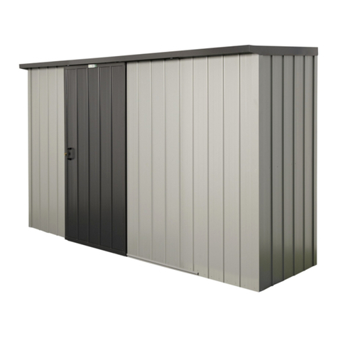
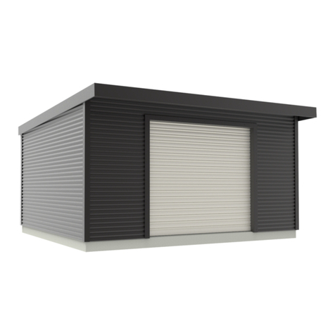
Dura Bike Locker DLMC User manual


DURA MOTORCYCLE LOCKER® DLMC ASSEMBLY INSTRUCTIONS
1. Levelers: Start by locating the (2) leveler plates, these are the back corners of the locker. Install
(1) leveler in each leveler plate. Note: Levelers may have been pre-installed.
2. Threshold: Next locate the threshold; this is for the front of the locker. This part takes (4)
levelers to support the vehicle passing over it. Once the levelers are installed set this part aside
until step 5.

3. Back Panel and Wall: Next locate a back panel (which has four sets of louvers) and a wall.
a. Place the back right leveler plate where the rear right corner of the locker will be located
then position the back panel on that plate and finally stand up the wall.
b. Attach the wall to the back panel using (4) pan head screws.
c. Now attach the back panel and wall to the leveler plate using (3) pan head screws.

4. Walls: Next locate (3) walls.
a. Position the left leveler plate under the back panel where the rear left corner of the locker
will be located then stand up (1) of the walls you located in step 4. Attach the wall to the
back panel using (4) pan head screws.
b. Attach the back panel and the wall you just installed to the leveler plate using (3) pan head
screws.
c. The next wall can now be installed, position it next to the wall you just installed in step 4a.
Attach it to the wall using (4) pan head screws and (4) matching nuts.

d. The last bottom wall can now be installed, position it next to the wall you installed in step 3.
Attach it to the wall using (4) pan head screws and (4) matching nuts.
5. Frame: The frame can now be assembled. Locate the (2) frames (these panels have louvers in
the top and bottom), (1) frame header and the threshold you prepared in step 2.
a. Attach the threshold and (1) frame using (2) pan head screws and ensure the louvers are
oriented correctly. Now attach the 2nd frame in the same manner.

b. Move the frame header into position between the two frames opposite the threshold.
c. Now attach the header to each frame using (2) pan head screws per frame.
d. Stand up the frame and position it in front of the parts you have already assembled.

e. Now attach the frame using (8) pan head screws, (4) for each side.
f. At this point the lower wall “L” channel stiffeners can be added. Using (6) #10 sheet metal
screws secure the stiffeners centered between the two walls.

6. Upper Walls: Locate another wall panel. We recommend two people for this step as these
panels are large. Lift and position the panel and mount it to the frame using (4) pan head
screws.
a. Now attach the upper wall to the lower wall using (5) pan head screws and the (5) matching
nuts.
b. The last upper wall on this side can now be installed. Using two people lift and position the
panel next to the wall you just attached. This can be attached to the wall next to it using (4)
pan head screws and the (4) matching nuts.

c. Now attach the upper wall to lower wall using (5) pan head screws and the (5) matching
nuts.
d. The rest of the walls on the opposite side of the locker can now be installed using the same
method as steps 6 - 6c. Once these panels are assembled you can install the vertical wall
“C” channel stiffeners (step 7).

7. Vertical Wall Stiffener: Center the right vertical wall stiffener between the walls then attach to
the walls using (12) sheet metal screws.
a. The left vertical stiffener can now be installed in the same manner as the right (step 7) using (12)
sheet metal screws.
8. Upper Back Panel: Locate the other back panel then lift and position it on top of the back panel
you installed step 3.

a. Mount the back panel to the walls using (8) pan head screws (4) for each side.
b. Now join the back panels together using (6) pan head screws and (6) matching nuts.
9. Rear Top Panel: Locate a top panel then, using at least two people, lift and position it on top of
the back panel you installed step 8 and the walls it is attached to.

a. The top is attached to the back panel using (4) pan head screws.
b. You can now secure the top to the walls using (10) pan head screws (5) for each
side.
10. Front Top Panel: The next top panel can be installed similarly to the rear top panel. Lift and
position it next to the top panel you installed step 9. At this time you can apply silicone to the
seam where the two top panels meet to ensure weather proofing.

a. Now secure the top to the walls using (10) pan head screws, (5) for each side.
b. Now attach the top to the frame header using (4) pan head screws.

c. A top stiffener can now be installed to ensure the rigidity of the top panels. Position it
between the two top panels and mount using (8) sheet metal screws.
11. Door Track Brackets: Now that the locker is assembled the door track can be installed. The
brackets are mounted using 5/16”-18 Bolts. Attach the lower track brackets using (4) bolts, (1)
for each bracket.

a. Locate the upper left bracket then attach it to the frame using (3) bolts.

b. Next the upper right bracket can be installed in the same manner as the left, attach
it to the frame using (3) bolts.
12. Rear Track Brackets: The rear track brackets can now be mounted using (4) sheet metal screws,
(2) for each bracket.

13. Roll-Up Garage Door: Now that the locker is completely assembled ensure all screws are tight
and all panels are flush. If anchoring is desired continue to the next step, otherwise refer to the
included assembly manual “Installation Instructions For Residential Garage Doors” to install the
tracks and roll-up door and enjoy your new Dura Motorcycle Locker!
14. Anchoring: The locker can be anchored to the concrete using the provided (2) redheads.
Anchors are placed in two corners of the locker.

a. Line up a Hammer Drill with a 3/8” bit suitable for concrete and drill a hole through the
leveler plate into the concrete.
b. Next the locker can be anchored to the ground, ensure the redhead is straight not crooked
when inserting it through the hole in the leveler plate and into the hole you drilled. Using a
hammer, pound the redhead into the ground (make sure you already have the nut on your
redhead before you begin hammering as they tend to mushroom where struck). Be careful
not to strike the locker, once the redhead is secure tighten the nut to anchor the locker in
place (do not over tighten).
END
Popular Outdoor Storage manuals by other brands
Tiger
Tiger TIGERFLEX NOVA General assembly instructions

Duratuf
Duratuf Garrison PL84 Assembly instructions

USP
USP DURAMAX 10.5 Ft x 8 Ft WoodBridge-V2 owner's manual

Palmako
Palmako Leif installation manual

USP
USP Duramaxx 7 Ft Store Max Plus owner's manual

Moebelix
Moebelix T-PSF56-H154 Assembly instructions

Karibu
Karibu 67417 Building instructions

Absco
Absco 1508BCK Assembly & instruction manual

CONFORAMA
CONFORAMA AMAZONE Assembling instructions

Arrow Storage Products
Arrow Storage Products EZEE SHED EZ107CCCR Owner's manual & assembly guide

ABSCO SHEDS
ABSCO SHEDS 30152GK-PTX Assembly instruction

Arrow
Arrow EH108-A Owner's manual & assembly instructions