Durapac P-2200 User manual

ABSOLUTE EQUIPMENT PTY LTD –2/186 Granite Street, GEEBUNG QLD 4034 –Australia
sales@absoluteequipment.com.au –Phone: +61 7 3865 4006 –Fax: +61 7 3102 6288
Maximum Operating Pressure –700 bar
Instruction Manual
2 Speed Hand Pump
Model –P-2200 & P-2200D

Instruction Manual
P-2200 & P-2200D Hand Pumps - V1.1 www.durapac.com Page 2 of 15
This is a safety alert symbol. It is used to alert you to potential personal injury hazards.
Obey all safety messages that follow this symbol to avoid injury or death
1.0 Product Information
DURAPAC –Hand Pumps are engineered to meet Industrial Standards for Performance and Safety.
The P-2200 is a 2 speed, steel bodied manual hand pump designed to be used with single acting
hydraulic equipment.
The P-2200D is a 2 speed, steel bodied manual hand pump with a 4 way valve designed to be used
with double acting hydraulic equipment.
Both model pumps feature a unique oil reservoir breather incorporating a pressure relief valve to
guard against accidental over pressurisation of the oil reservoir. They are robustly built, industry
proven performers, with a low handle effort for ease of operation and large easy to grip external
pressure release knobs.
Special skill, knowledge and training may be required for a specific task and the product may not be
suitable for all jobs. The user must ultimately make the decision regarding suitability of the product
for any given task and assume the responsibility of safety for all in the work area. Contact a Durapac
representative if you are unsure of your hand pumps suitability for a particular application.
2.0 Receiving Instructions
It is recommended prior to use that an inspection be done by qualified personnel and that any
missing or damaged parts, decals, warning/safety labels or signs are replaced with Durapac
authorised replacement parts only. Any hand pump that appears to be damaged in any way, is worn,
leaking or operates abnormally should be removed from service immediately until such time as
repairs can be made. Any hand pump that has been or suspected to have been subject to a shock
load should be removed from service immediately until inspected by a Durapac authorised service
centre. Owners and operators of this equipment should be aware that the use and subsequent
repair of this equipment may require specialised training and knowledge.
3.0 Safety
Save these instructions. For your safety, read and understand the information contained within. The
owner and operator should have an understanding of this product and safe operating procedures
before attempting to use this product. Instructions and safety information should be conveyed in the
operator's native language before use of this product is authorised. Make certain that the operator
thoroughly understands the inherent dangers associated with the use and misuse of the product. If
any doubt exists as to the safe and proper use of this product as outlined in this factory authorised
manual, remove from service immediately.
DANGER:
To avoid personal injury keep hands and feet away from work area during operation
Do NOT handle pressurised hoses. Escaping oil under pressure can penetrate the skin
causing serious injury. If oil is injected under the skin, see a doctor immediately

Instruction Manual
P-2200 & P-2200D Hand Pumps - V1.1 www.durapac.com Page 3 of 15
Stay clear of loads supported by hydraulics. A cylinder, when used as a load lifting
device, should never be used as a load holding device. After the load has been raised
or lowered, it must always be blocked mechanically
WARNING:
The system operating pressure must not exceed the pressure rating of the lowest
rated component in the system. Install pressure gauges in the system to monitor
operating pressure. It is your window to what is happening in the system
Always wear protective gear when operating hydraulic equipment. The operator must
take precaution against injury due to failure of the tool or work piece(s)
Do NOT hold or stand directly in line with any hydraulic connections while pressurising
Do NOT attempt to disconnect hydraulic connections under pressure. Release all line
pressure before disconnecting hoses
All personnel must be clear before lowering load or depressurising the system
Do NOT attempt to lift a load weighing more than the capacity of the cylinder
IMPORTANT:
If at any stage, the safety related decals become hard to read, these must be replaced
Minimum age of the operator must be 18 years. The operator must have read and
understood all instructions, safety issues, cautions and warnings before starting to
operate the equipment. The operator is responsible for this activity towards other
persons
Do NOT lift hydraulic equipment by the hoses or couplers. Use the carrying handle or
other means of safe transport
Hydraulic equipment must only be serviced by a qualified hydraulic technician. For
repair service, contact the Durapac authorised service centre in your area. To protect
your warranty, use only high quality hydraulic oil
CAUTION:
KEEP HYDRAULIC EQUIPMENT AWAY FROM FLAMES AND HEAT. Hydraulic fluid can
ignite and burn. Excessive heat will soften packings and seals, resulting in fluid leaks.
Heat also weakens hose materials and packings. For optimum performance do not
expose equipment to temperatures of 65°C (150°F) or higher. Protect all equipment
from weld spatter
No alteration should be made to this device
3.1 Hydraulic Pumps
Do use a gauge or other load measuring instrument to verify load
Do NOT exceed the rated capacity of the pump or any equipment in the system.
Burst hazard exists if connection pressure exceeds rated pressure
Do NOT operate the system with bent or damaged couplers or damaged threads
Do NOT subject the pump and its components to shock loads

Instruction Manual
P-2200 & P-2200D Hand Pumps - V1.1 www.durapac.com Page 4 of 15
Use only Durapac approved accessories and components
Do NOT connect to an application which can return more oil to the reservoir than
the pump reservoir can hold
Do NOT connect pump to a hydraulic system that is powered by another pump
3.2 Hydraulic Hoses & Fluid Transmission Lines
Avoid short runs of straight line tubing. Straight line runs do not provide for
expansion and contraction due to pressure and/or temperature changes
Reduce stress in tube lines. Long tubing runs should be supported by brackets or
clips. Before operating the pump, connections should be tightened securely and
leak-free. Over tightening can cause premature thread failure or high pressure
fittings to burst
Should a hydraulic hose ever rupture, burst or need to be disconnected,
immediately shut off the pump and release all pressure. Never attempt to grasp a
leaking pressurised hose with your hands. The force of escaping hydraulic fluid can
inflict injury
Do NOT subject the hose to potential hazard such as fire, sharp objects, extreme
heat or cold or heavy impact
Do NOT allow the hose to kink, twist, curl, crush, cut or bend so tightly that the fluid
flow within the hose is blocked or reduced. Periodically inspect the hose for wear
Hose material and coupler seals must be compatible with the hydraulic fluid used.
Hoses also must not come in contact with corrosive materials such as battery acid,
creosote-impregnated objects and wet paint. Never paint a coupler or hose
FAILURE TO HEED THESE WARNINGS MAY RESULT IN PERSONAL INJURY AS WELL AS PROPERTY DAMAGE.
4.0 Installation
IMPORTANT: Always secure threaded port connections with high grade, non-hardening pipe
thread sealant. Teflon tape can be used if only one layer of tape is used and it is applied
carefully, two threads back, to prevent the tape from being introduced into hydraulic system,
which could cause jamming of precision-fit parts
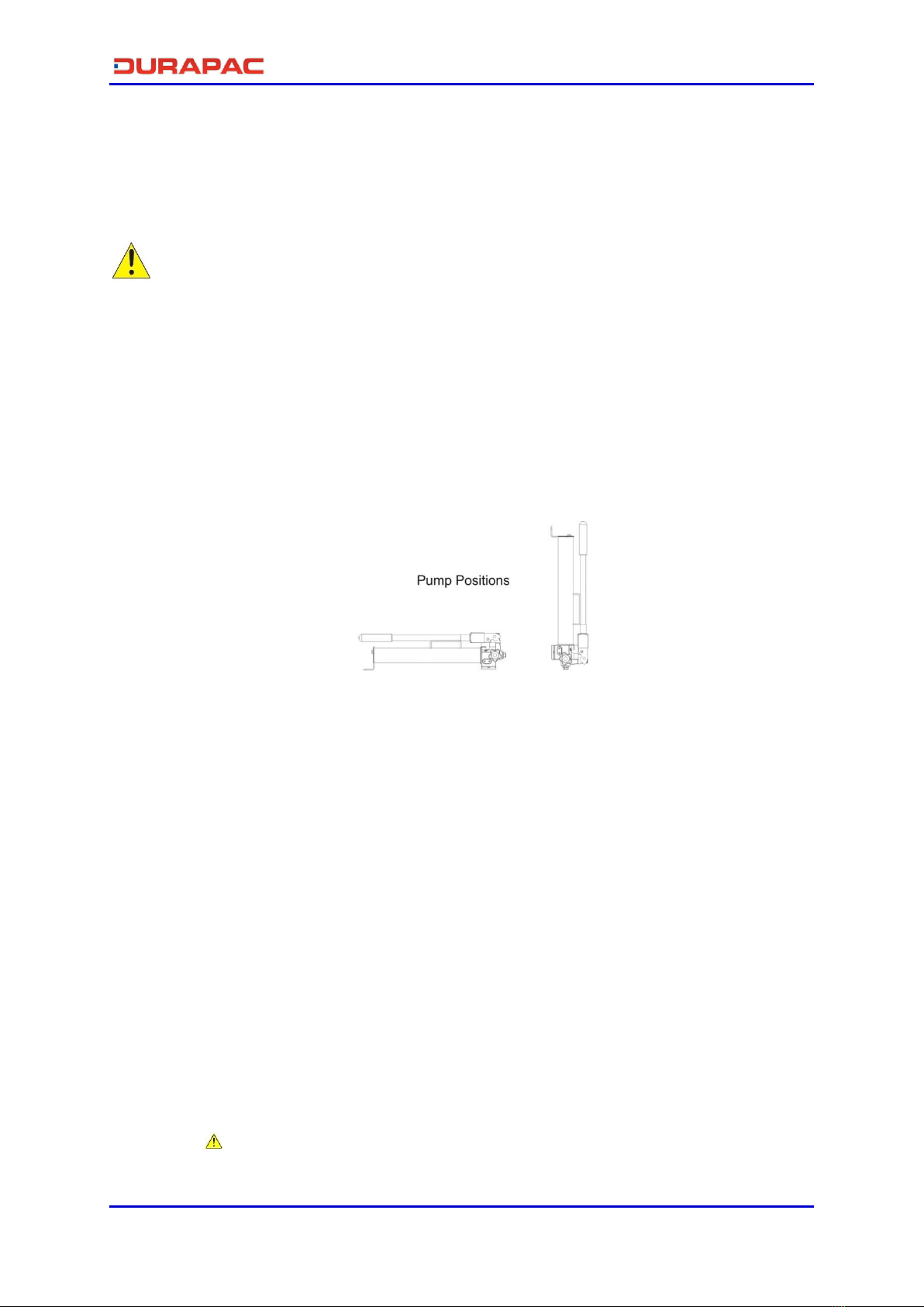
4.1 Familiarise yourself with the specifications and illustrations in this owner’s manual.
Know your hand pump, its limitations and how it operates before attempting to use.
Refer to the specification chart below or if in doubt, contact a Durapac representative.
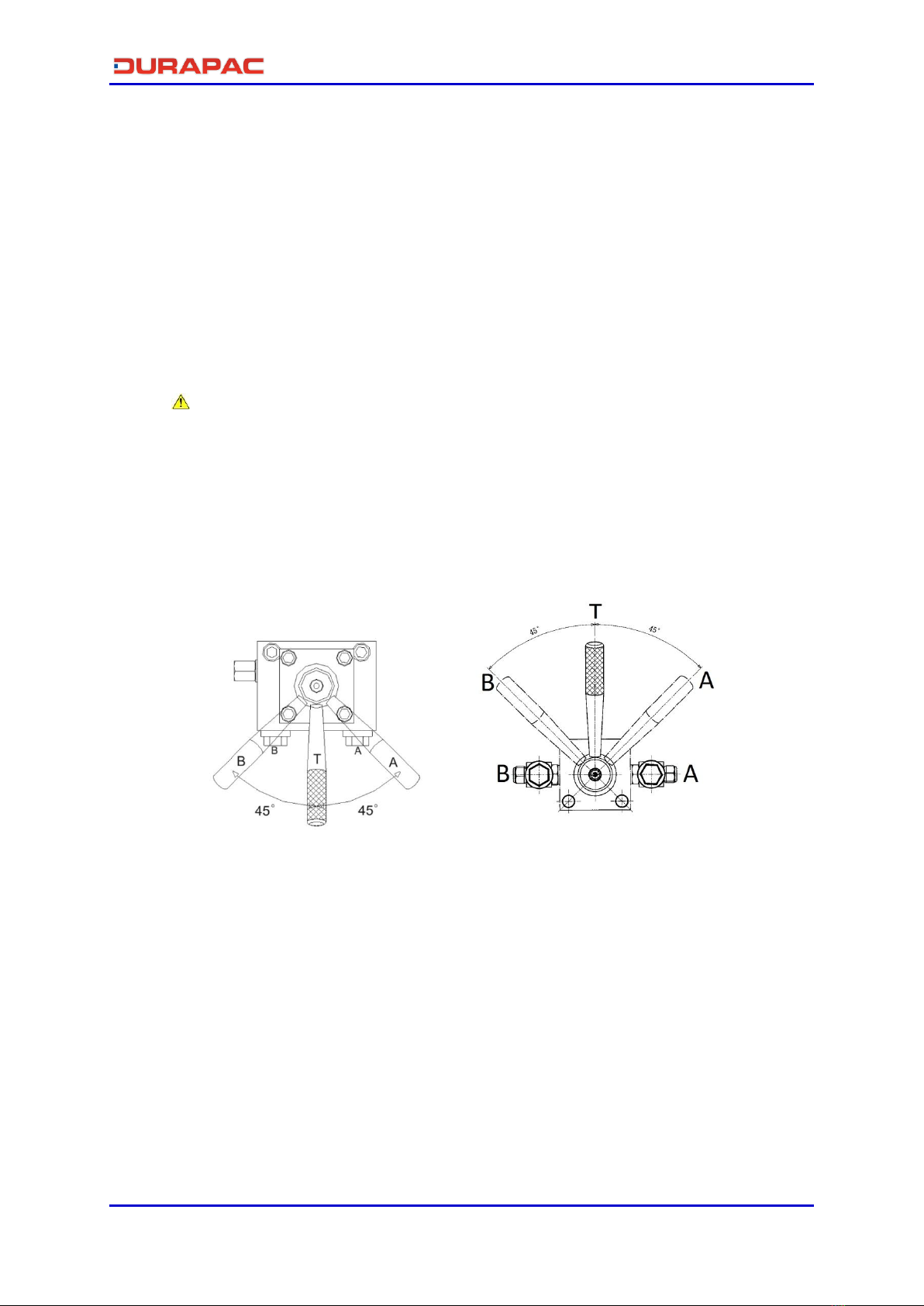
4.2 Remove plug/s from outlet port/s and connect hoses or couplings to the pump.
1st Stage 2nd Stage 1st Stage 2nd Stage
P-2200 S/A 2 Way 13.8 700 2,000 13.0 2.8 3/8" NPTF 35 11.5
P-2200D D/A 4 Way 13.8 700 2,000 13.0 2.8 3/8" NPTF 37 11.5
Weight
(kg)
Max
Handle
Effort (kg)
Valve
Type
Model
Number
Used
with
Cylinder
Pressure Rating
(bar)
Usable Oil
Capacity
(cc)
Oil Volumes
per Stroke (cc)
Oil Port
Thread

Instruction Manual
P-2200 & P-2200D Hand Pumps - V1.1 www.durapac.com Page 5 of 15
4.3 Remove air from the system –Air can accumulate in the hydraulic system during the
initial setup or after prolonged use, causing the cylinder to respond slowly or in an
unstable manner. Should removal of air from pump be required, please follow the
steps in 6.2 –Bleeding Air from the System in the Maintenance Section.
5.0 Operation
IMPORTANT:
Do NOT add extensions to the pump handle. Extensions cause unstable pump
operation
In certain situations the pump handle can "kick back". Always keep your body to the
side of the pump, away from the line of force of the handle
Do NOT operate a pump that is disconnected from application. If operated in this
condition, the hose and connections will become pressurised. This increases burst
hazard. Damage may occur to pump and its components
The pump may be operated in a horizontal or in a vertical position with the head pointing down
as shown.
Figure 1 –Hand Pump Operation
5.1 Before Using the Pump
5.1.1 Check all system fittings and connections to be sure they are tight and leak free.
5.1.2 Check oil level in reservoir before operating pump.
5.2 Using Two-Speed Pumps
This pump provides 2-stage flow. Under no-load, the pump operates in the high flow
first stage for rapid advance. When the load is contacted, the pump automatically shifts
to the second stage for building pressure. After the pump shifts, pumping takes less
effort.
Note: To reduce handle effort at high pressure, take short strokes. Maximum leverage
is obtained in the last 5° of stroke. For best performance, operate pump handle at
moderate speed during the high flow first stage. Rapid handle speed in the first stage
will prevent the pump from delivering full volume of oil.
5.3 Advance and Retraction of Single-Acting Applications
5.3.1 Turn the pump’s release valve clockwise to a closed position.
IMPORTANT: Only hand tighten the valve. Applying too much force to the valve
may damage the valve stem.

Instruction Manual
P-2200 & P-2200D Hand Pumps - V1.1 www.durapac.com Page 6 of 15
5.3.2 Work the pump handle up and down to send oil through the hose to the
cylinder, causing the piston to extend to the work piece.
5.3.3 Monitor the pressure gauge while completing the application.
Note: The pump is equipped with an overload valve that will bypass oil back into the
pump reservoir in an overload situation (when the system meets maximum pressure).
In this case, continued pumping will have no effect on the system. If an overload
situation commonly occurs, a higher capacity set is needed.
5.3.4 To release pressure, slowly turn the release valve counter clockwise. The
release speed is controlled by how fast the valve is opened.
5.4 Double-Acting Applications with 4 Way Valve
WARNING: Only operate a double-acting cylinder after both hoses have been
connected to the pump. If one coupler is left unconnected, high pressure will build
behind the coupler which could cause personal injury and/or equipment damage.
Pumps with 4-way control valves are designed to operate double-acting cylinders.
Note –there are two versions of the 4 way valve that may be used by the P-2200D. The
serial number (of the P-2200D) can be used to identify the applicable 4 way valve
positioning for your pump.
Serial No. 11024166 and below Serial No. 11056050 and above
Figures 2 & 3 –4 Way Valve Positioning
5.4.1 Position lever on 4-way valve to select function as follows:
(A) Flow to Port "A"; port "B" returns flow to the reservoir
(T) Neutral; ports "A" and "B" are blocked
(B) Flow to port "B"; port "A" returns flow to the reservoir
5.4.2 Operate pump to perform work.
5.4.3 Change valve positions as needed.
5.5 Relief Valve Adjustment
All pumps contain a factory set relief valve to prevent over-pressurisation of the
system.

Instruction Manual
P-2200 & P-2200D Hand Pumps - V1.1 www.durapac.com Page 7 of 15
6.0 Maintenance
IMPORTANT:
Check oil level regularly
Use only good quality hydraulic fluid. Do NOT use brake fluid, transmission fluid,
turbine oil, motor oil, alcohol, glycerine etc. Use of anything other than good quality
hydraulic oil will void warranty and damage the pump, hose, and application. We
recommend Durapac Hydraulic Oil or equivalent
Equipment must only be serviced by a qualified hydraulic technician. For repair service,
contact your local Durapac authorised service centre
Tighten connections as needed. Use non-hardening pipe thread compound when
servicing connections.
Dirt, sand, etc. will quickly ruin any hydraulic system. Ensure that couplings are clean and free of
foreign matter. After each use, clean couplings and attach dust caps.
Maintenance is required when wear or leakage is noticed. Periodically inspect all components to
detect any problem that may require service and maintenance.
6.1 Adding Hydraulic Fluid
WARNING: Always add oil with cylinders fully retracted (or extended, if pull cylinders) or
the system will contain more oil than the reservoir can hold
6.1.1 Depressurise and disconnect hydraulic hose from application/cylinder.
6.1.2 Close the air vent.
6.1.3 Put the pump in a vertical position (pump head face down), remove oil filler
plug (has attached dipstick) located on rear of the pump reservoir.
6.1.4 Use a small funnel to fill the reservoir to approximately 90 mm from the top of
the oil filler hole.
6.1.5 Bleed air from system if necessary.
6.1.6 Wipe up any spilled fluid and reinstall the air vent plug/reservoir cap.
6.2 Bleeding Air from the System
Air can accumulate in the hydraulic system during the initial setup or after prolonged
use, causing the cylinder / spreader to respond slowly or in an unstable manner. To
remove the air:
Figure 4 –Bleeding Air from the System

Instruction Manual
P-2200 & P-2200D Hand Pumps - V1.1 www.durapac.com Page 8 of 15
6.2.1 Pump With Single-Acting Cylinder (A)
6.2.1.1 Repeat Steps 6.1.1 to 6.1.4 (above), if required.
6.2.1.2 Position pump at higher elevation than cylinder.
6.2.1.3 Position cylinder with the piston rod end down (up if using pull
cylinder).
6.2.1.4 Open Pump Breather Valve (4 Turns)
6.2.1.5 Operate pump to fully extend the cylinder (retract if using pull cylinder).
6.2.1.6 Open release valve to retract cylinder (extend if a pull cylinder). This will
force the trapped air to move up to the pump reservoir.
6.2.1.7 Repeat the above steps as necessary.
6.2.1.8 Recheck oil level after removing air.
6.2.1.9 Return vent/fill cap to operating position.
6.2.2 Pump With Double-Acting Cylinder (B)
6.2.2.1 Repeat Steps 6.1.1 to 6.1.4 (above), if required.
6.2.2.2 Position pump at higher elevation than cylinder.
6.2.2.3 Put cylinder in horizontal position with ports up.
6.2.2.4 Fully advance and retract the cylinder 2 to 3 times.
6.2.2.5 Repeat the above steps as necessary.
6.2.2.6 Recheck oil level after removing air.
6.2.2.7 Return vent/fill cap to operating position.
6.3 Changing Hydraulic Fluid
For best results, change fluid once a year or every 300 hours of use
6.3.1 Repeat Steps 6.1.1 to 6.1.3 (above).
6.3.2 Pour used fluid into a sealable container.
6.3.3 Repeat Steps 6.1.4 to 6.1.6 (above).
6.3.4 Dispose of fluid in accordance with local regulations.
6.4 Lubrication
To extend pump life and improve performance, lubricate the beam pin (A), cross pin
(B), and piston head (C) regularly, using roller bearing grease.
Figure 5 - Lubrication

Instruction Manual
P-2200 & P-2200D Hand Pumps - V1.1 www.durapac.com Page 9 of 15
6.5 Storage
6.5.1 When not in use, depressurise and disconnect the hydraulic pump from the
application.
6.5.2 Wipe clean thoroughly and store in a clean, dry environment. Avoid
temperature extremes.
6.5.3 Shield pump with protective cover.

Instruction Manual
P-2200 & P-2200D Hand Pumps - V1.1 www.durapac.com Page 10 of 15
7.0 Troubleshooting
Problem
Cause
Solution
Pump loses pressure
Leaking system components
Repair or replace as necessary
Pump not delivering fluid
Low fluid level in reservoir
Check fluid level
Worn seats
Repair seats
Replace pump body
Pump does not reach
rated capacity
Low fluid level in reservoir
Check fluid level
Leaking system components
Repair or replace as necessary
Fluid leaking past inlet or outlet
checks
Repair inlet or outlet checks
Replace high pressure piston
seal
Pump handle has a
“spongy” feel
Air trapped in system
Refer to 6.2 - Bleeding Air from
the System
Too much fluid in reservoir
Check fluid level
Cylinder piston will not
extend
Loose couplers
Tighten couplers
Low fluid level in pump
reservoir
Fill and bleed the system
Leaking cylinder seals
Replace worn seals. Look for
excessive contamination or
wear
Cylinder piston extends
only partially
Low fluid level in pump
reservoir
Fill and bleed the system
Load above capacity of system
Use correct equipment
Cylinder piston extends
slower than normal
Loose couplers
Tighten couplers
Restricted hydraulic line or
fitting
Clean and replace if damaged
Pump not operating correctly
Check pump’s operating
instructions
Repair or replace as necessary
Low fluid level in pump
reservoir
Fill and bleed the system
Cylinder does not hold
pressure
Leaky connection
Clean, reseal with thread
sealant, and tighten
connection
Leaking cylinder seals
Replace worn seals. Look for
excessive contamination or
wear. Replace contaminated
fluid
Pump or valve not operating
correctly
Repair or replace as necessary
Cylinder will not retract or
retracts slower than
normal
Closed pump release valve
Open pump release valve
Loose couplers
Tighten couplers
Blocked hydraulic lines
Clean and flush lines
Weak or broken retraction
springs
Send to a Durapac authorised
service centre for repair
Internally damaged cylinder
Send to a Durapac authorised
service centre for repair
Pump reservoir too full
Drain fluid to correct level

Instruction Manual
P-2200 & P-2200D Hand Pumps - V1.1 www.durapac.com Page 11 of 15
Item Description Part No. Qty Item Description Part No. Qty Item Description Part No. Qty
1 Pump housing ZAL1188 1 16 O-ring* ZAL1279 1 31 Valve cover screw ZAL1286 2
2 Oil filter ZAL1387 1 17 Back-up ring* ZAL1225 1 32 Steel ball ZAL1370 2
3 O-ring* ZAL1235 1 18 Pump piston ZAL1103 1 33 Spring end cap ZAL1096 2
4 Tie rod ZAL1109 1 19 Yoke ZAL1176 1 34 Short separator spring ZAL1350 1
5 Reservoir ZAL1033 1 20 Yoke pin ZAL1095 1 35 Screw ZAL1175 2
6 O-ring* ZAL1207 2 21 Piston pin ZAL1108 1 36 Long separator spring ZAL1346 1
7 Nipple ZAL1094 1 22 Retaining ring ZAL1327 1 37 Set screw ZAL1294 2
8 Steel ball ZAL1366 4 23 Yoke cover ZAL1226 1 38 Oil seal* ZAL1224 1
9 Screw ZAL1284 3 24 Handle ZAL1080 1 39 Washer ZAL1351 1
10 O-ring ZAL1229 2 25 Handle grip ZAL1263 1 40 Coupler ZAL1291 1
11 Nipple ZAL1264 2 26 Steel ball ZAL1367 2 41 Release valve ZAL1004 1
12 O-ring* ZAL1272 1 27 Spring ZAL1344 2 42 Pin ZAL1371 1
13 Back-up ring* ZAL1209 1 28 Steel ball ZAL1368 2 43 Vent screw ZAL1034 1
14 Pump piston ZAL1110 1 29 Spring ZAL1339 2 44 Air vent ZAL1036 1
15 Snap ring ZAL1329 1 30 Washer ZAL1340 2 Repair kit ZAL1324 1
8.0 Parts Breakdown and List
8.1 P-2200 Model

Instruction Manual
P-2200 & P-2200D Hand Pumps - V1.1 www.durapac.com Page 12 of 15
Note –there are two versions of the 4 way valve that may be used by the P-2200D. The serial
number (of the P-2200D) may be used to identify the applicable parts breakdown for your pump.
8.2 P-2200D Model (P-2200 Pump + VM4-2200 4-way valve) - Serial
Numbers 11024166 and below
Item Description Part No. Qty
1 Hand pump P-2200 1
2 4-way valve VM4-2200 1
3 Back-up ring ZAL1250 4
4 O-ring ZAL1251 4
5 Connected tube ZAL1568 2
6 Nipple ZAL1264 2
7 Screw ZAL1569 4

Instruction Manual
P-2200 & P-2200D Hand Pumps - V1.1 www.durapac.com Page 13 of 15
Item Description Parts No. Qty
1 Valve base ZAL1053 1
2 Steel ball ZAL1366 1
3 Screw ZAL1284 1
4 Steel ball ZAL1367 5
5 Spring ZAL1358 3
6 Spring ZAL1362 2
7 Screw ZAL1305 5
8 O-ring ZAL1276 2
9 O-ring end cap ZAL1131 2
10 Ball seat ZAL1133 2
11 High pressure rod ZAL1378 2
12 Push bar ZAL1380 1
13 Low pressure rod ZAL1379 2
14 Steel ball ZAL1377 5
15 Control switch ZAL1132 1
16 O-ring ZAL1251 1
17 Bearing ZAL1374 1
18 O-ring ZAL1265 1
19 Top plate ZAL1060 1
20 Pin ZAL1335 2
21 Screw ZAL1317 4
22 Switch base ZAL1162 1
23 O-ring ZAL1215 1
24 Washer ZAL1364 1
25 Screw ZAL1311 1
26 Valve handle ZAL1160 1
8.2.1 VM4-2200 Model (4-way valve attachment)

Instruction Manual
P-2200 & P-2200D Hand Pumps - V1.1 www.durapac.com Page 14 of 15
8.3 P-2200D Model (P-2200 Pump + VM4-2200 4-way valve) –Serial
Numbers 11056050 and above
Item Description Part No. Qty
1 Hand pump P-2200 1
2 Back-up ring ZAL1250 4
3 O-ring ZAL1251 4
4 Connection tube ZAL1568 2
5 4-way valve VM4-2200 1
6 Copper washer ZAL1264 4
7 Bolt ZAL1570 4

Instruction Manual
P-2200 & P-2200D Hand Pumps - V1.1 www.durapac.com Page 15 of 15
8.3.1 VM4-2200 Model (4-way valve attachment)
Item Description Parts No. Qty
1 Shear seal plate ZAL1552 1
2 O-ring ZAL1553 3
3 Back-up ring ZAL1554 3
4 Thrust washer ZAL1555 3
5 Shear seal A ZAL1556 3
6 Valve rotor ZAL1557 1
7 O-ring ZAL1251 1
8 Bearing ZAL1558 1
9 O-ring ZAL1559 1
10 Top plate ZAL1560 2
11 Pin ZAL1378 2
12 Steel ball ZAL1366 3
13 Spring ZAL1561 1
14 Switch base ZAL1562 1
15 Toothed lock washer ZAL1563 1
16 Screw ZAL1311 1
17 Handle ZAL1160 1
18 Screw ZAL1164 2
19 Screw ZAL1284 2
20 Oil pressure valve assy ZAL1165 2
21 Back-up ring ZAL1218 4
22 O-ring ZAL1274 4
23 Coupler body ZAL1266 2
24 Anti-loosen nut ZAL1267 2
25 O-ring ZAL1229 2
26 Nipple ZAL1264 2
This manual suits for next models
1
Table of contents
Other Durapac Water Pump manuals