Duron K7V266A User manual

K7V266A
(VIA KT266A Chipset, Socket-462)
For AMD®Athlon XP/ Athlon/ Duron CPUs
With DDR 266 Memory
ATX Form Factor
Main Board
User’s Manual
(Ver.:1.0)

Copyright
Copyright©2001 by this company. No part of this document may be
reproduced, transmitted, transcribed, stored in a retrievable system,
or translated into any natural or computer language, in any form or
by any means without prior written permission. This manual and the
information contained here are protected by copyright. All rights
reserved.
Copyright 2001. All Rights Reserved.
Revision History
Revision Date Release Notes
1.0 Jan.-2001 First Official Release

Warning and disclaimer
This manual is designed to provide information about the AMD®
Athlon XP/ Athlon/ Duron mainboard. Effort have been made to
make this manual as accurate as possible, but no warranty or fitness
is implied. All the information is provided on an 'as is' basis. The
author and his corresponding publishing company shall have neither
liability nor responsibility to any person or entity with respect to any
loss or damages arising from the information contained in this
manual or from the use of the system board that accompanies it.
Information contained in this manual is subject to change without
notice. The manufacturer of the system board will not be held
responsible for technical or editorial omissions made herein, nor for
the incidental or consequential damages resulting from its
furnishing, performance, functionality or use. Subsequent changes to
this manual will be incorporated into the next edition. We welcome
any suggestion regarding this manual or our computer products.
Trademarks
●IBM®is a registered trademark of International Business Machines
Corporation.
●Microsoft®is a registered trademark of Microsoft®Corporation.
●PCI®is a registered trademark of PCI®Special Interest Groups.
●AWARD®is a registered trademark of Award Software Inc.
All other trademarks are the property of their respective owners.

I
Table of Contents
Chapter 1 Introduction…………………………………………1
1-1 Main Specifications……………………………………………………2
1-2 System Configuration……………………………………………..……4
1-3 Notice of Hardware Installation………….……………………....……5
Chapter 2 Installation……………….……………………….…6
2-1 Component Locations …………………..…………………………..…6
2-2 Layout Reference……………………………………………..………..7
2-3 Jumper Setting…………………………………………………………8
2-3-1 JP1: AC97 & MC97 Status Selector…………………………………8
2-3-2 JP2 & SW1: CPU Frequency Selector………………………………9
2-4 CPU Installation………………. ……………………………………10
2-3-1 CPU and System Cooling………………………….…………………13
2-5 Connectors………..……………………………………………………14
2-5-1 Front Panel…………………………………………………….………14
2-5-2 Back Panel Connectors………………………………………………16
2-5-3 Power Supply Connector……………………………………………18
2-5-4 Floppy Disk Connector………………………………………………18
2-5-5 IDE1 and IDE2………………………………………………………20
2-5-6 IR1: IrDA Connector…………………………………………………21
2-5-7 WOM1: Wake Up On Modem………………………………………22
2-5-8 WOL1:WakeUp On LAN (Optional)………………………………23
2-6 Memory………………………………………………………………24
2-6-1 Memory Installation…………………………………………………25
Chapter 3 Software Installation………………………………26
3-1 Notice of Driver Installation…………………………………………26
3-2 How to Install Software Drivers…………………………………….27

II
Chapter 4 The BIOS…..………………………………………28
4-1 Updating the BIOS……………………………………………………29
4-2 The CMOS Memory…………………………………………………30
4-3 The BIOS Setup Pages………………………………………………32
4-3-1 Standard CMOS Setup………………………………………………35
4-3-2 BIOS Features Setup…………………………………………………39
4-3-3 Chipset Features Setup………………………………………..……43
4-3-4 Integrated Peripherals………………………………………..……...48
4-3-5 Power Management Setup………………………………………….53
4-3-6 PNP/PCI Configuration Setup……………………………………….57
4-3-7 PC Health Status……………………………………………………59
4-3-8 Frequency/Voltage Control.…………………………………………60
4-3-9 Passwords Setting……………………………………………………..61
Chapter 5 Appendix………………………………….………63
5-1 Memory Map………………………………………………….………63
5-2 I/O Map………………………………...….………………………….64
5-3 Time & DMA Channels Map…………………………………………65
5-4 Interrupt Map………………………………………….……………...66
5-5 RTC & CMOS RAM Map………………………………………….67
5-6 ISA I/O Address Map……………………………………………..68
Chapter 6 Q & A…………………………………………………………………70
Important Warnings:
STOP
WARNING: NEVER run the processor without the heatsink properly and firmly
attached. This will damage the processor within SECONDS. Also do NOT try to use
Pentium Heatsinks, these will NOT fit and do NOT provide adequate cooling.
STOP
WARNING: Make sure your power supply can deliver the power your system needs.
We recommend AT LEAST a 250W power supply. Even better, get a 300W power
supply, especially when using many peripherals.

1
Chapter 1 Introduction
Thank you for purchasing this high quality motherboard, we are confident that you will be
able to use this motherboard to your full satisfaction. This manual is divided into 6 main
sections, as described below:
.
Introduction
The introduction contains information on the main specifications for this motherboard, the
package contents and cautionary notes.
Hardware Installation
The Hardware Installation section is the most important in the manual. It describes in detail
how to set the motherboard up for operation. Read all information and follow all steps,
especially if you are a new user.
Software Installation
The software section describes the drivers that need be installed to make your OS operates
properly. The drivers are provided on the driver CD.
BIOS Setup
Information on how to enter the BIOS setup and change settings is given here. In addition
all individual BIOS items are described. Although some BIOS setting information is given
in the hardware installation section where appropriate, refer to the BIOS Setup Section for
details.
Appendix
Provides useful information
Q & A

2
1-1 Main Specifications
PCB board size and form factor: 24.5 x 30.5cm, ATX type.
PCB layer: 4 layers
Supported CPUs
Can support the latest 200/ 266MB FSB Socket-462 AMD Athlon XP (up to 2000+)/
Athlon (up to 1.4GHz) or Duron (up to 1.2GHz) CPUs or higher speed.
Chipset Northbridge
The VIATM KT266A system controller is a 200/ 266MHz System Bus. The DRAM
controller supports DDR200/ DDR266 Double Data Rated (DDR) SDRAM; it complies
with AGP 2.0 specifications for 4X, 2X AGP modes and PCI 2.2 bus interface with support
for 6 PCI masters. It was designed especially to deliver enhance AMD®Athlon XP/ Athlon
or Duron processor system performance.
Chipset Southbridge
The VT8233 PCI Super-I/O Integrated Peripheral Controller (PSIPC) support Ultra/DMA/
100, which allows burst mode data transfer rates of up to 100MB/ sec; AC97 audio (using
the on-board VIA VT1611A Audio Cadec); USB controller with root hub and four function
ports.
Memory
This motherboard comes equipped with three Double Data Rate (DDR) Memory Module
sockets to support DDR 200MHz/ 266MHz-compliant (128, 256MB, or 512MB) DDR
Modules up to 3GB.
AGP (Accelerated Graphics Port)
This motherboard comes with an AGP slot with support for AGP cards for high
performance. The AGP 66MHz 4X mode is supported as well, further increasing system
performance.
PCI Expansion Slots
With six 32-bit PCI (Rev. 2.2) expansion slots, which can support Bus Master PCI cards,
such as LAN or Video-grabber cards (PCI supports up to 133MB/s maximum throughput),
this motherboard is ready for the most demanding applications.

3
CNR Slot
A Communication Networking Riser (C.N.R.) slot can be fitted with CNR MODEM, or
MODEM.
USB interface
With support for up to 6 USB ver 1.1 ports, four on-board, this motherboard provides
ample USB expansion room.
IDE interface
This motherboard comes with an onboard PCI Bus Master IDE controller with two
connectors that support four ATA66/ 33 devices on two channels. Supports UDMA/100,
UDMA/66, UDMA/33, PIO Modes 3 & 4 and Bus Master IDE DMA Mode 2, and
Enhanced IDE devices, such as CD-R/ RW, DVD-ROM, CD-ROM, Tape Backup and LS-
120 drives.
Super Multi-I/O
This functionality is integrated into the southbridge of the chipset. It provides two high-
speed UART compatible serial ports and one parallel port with EPP and ECP capabilities.
Infrared (IrDA) Connector
This functionality is also integrated into the southbridge of the chipset. The IrDA connector
supports an optional IR remote control device for wireless interfacing with external
peripherals, personal gadgets, or an optional remote controller.
System BIOS
This motherboard comes with a 2MB BIOS that provides CPU/ SDRAM frequency, boot
block write protection, and HD/ SCSI/ CD/ Floppy boot selection. DMI is also supported
through BIOS, which allows hardware to communicate within a standard protocol creating
a higher level of compatibility.
4
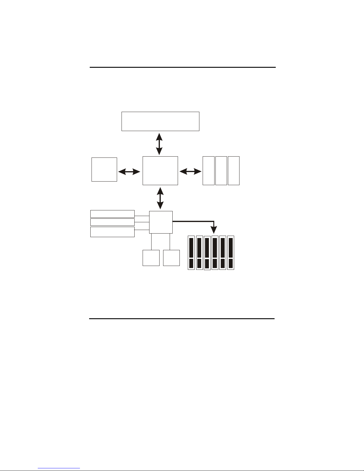
1-2 System Configurations
Below is the VIA KT266A chipset based system configuration:
VIA
KT266A
AMD Athlon XP/ Athlon/
Duron processor
System Bus
3.2GB/s
2.1GB/sec
8-Bit Hub
Interface
26MB/s
AGP4X (1.5V)
1.06GB/s
DDR200/266
AGP Slot or
3D Graphics
Controller
AC-97 Modem CODEC
(optional)
2 ATA100 IDE Channels
6 USB 1.1 Ports
PCI Bus
SIO Flash
BIOS
DDR200/266
DDR200/266
VIA
VT 8233

5
1-3 Notice of Hardware Installation
Before hardware installation, make sure you have checked the following things.
A. Check the package
If any of these items is missing or damaged, contact the dealer from whom you purchase.
Leave this main board in its original package until you are ready to install it. In the
package, there are:
➨
This motherboard
➨
1 Manual
➨
1 Driver Installation CD-ROM
➨
1 IDE ATA 66/100 Flat-Cable
➨
1 Floppy Disk Drive Flat-Cable
B. Make sure power is off.
During hardware installation, be sure that there is no power connected during this period.
C. Avoid ESD (Electrical Static Discharge.)
While installing the main board, wear a grounded wristband or ankle strap to avoid ESD
(Electrical Static Discharge).
Table of contents


