E.F. Johnson Company 751 series User manual

Revised July 1999
Part No. 001-7500-002
751x (VHF)
754x (UHF)
CONVENTIONAL
TWO-WAY RADIO
VHF 136-150 and 146-174 MHz
1 and 5 Watts, 9.6 VDC
UHF 400-430, 440-470, 470-500, and 490-512 MHz
1 and 4 Watts, 9.6 VDC
Copyright ©1999 by the E.F. Johnson Company
E.F. Johnson Company, which was founded in 1923, designs, manufactures, and markets
radio communication products, systems, and services worldwide. E.F. Johnson produces
equipment for land mobile radio and mobiletelephone services which include business,
industrial, government, public safety, and personal users.
Viking Head/EFJohnson® logo and Call Guard® are registered trademarks of the E.F.
Johnson Company. Smartrunk II™ is a trademark of Smartrunk Systems Inc. All other
company and/or product names used in this manual are trademarks and/or registered
trademarks of their respective manufacturer.
Information in this manual is subject to change without notice.

TABLE OF CONTENTS
ii
Revised July 1999
Part No. 001-7500-002
1 GENERAL INFORMATION
1.1 SCOPE OF MANUAL ....................1-1
1.2 TRANSCEIVER DESCRIPTION ...........1-1
1.3 PART NUMBER BREAKDOWN...........1-1
1.4 TRANSCEIVER IDENTIFICATION.........1-1
1.5 ACCESSORIES .........................1-1
1.6 PRODUCT WARRANTY .................1-1
1.7 FACTORY CUSTOMER SERVICE.........1-2
1.8 FACTORY RETURNS....................1-3
1.9 REPLACEMENT PARTS .................1-3
1.10 INTERNET HOME PAGE.................1-3
1.11 INSTALLING OPTION UNIT ..............1-3
1.12 TWO-TONE DECODER SETUP...........1-4
InstallationandProgramming............... 1-4
SettingToneFrequencies.................. 1-4
1.13 FIVE-TONE ENCODER/DECODER SETUP.1-5
InstallationandProgramming............... 1-5
Setting5-ToneDeviation.................. 1-5
1.14 RADIO DISASSEMBLY PROCEDURE.....1-6
RemovingChassis........................ 1-6
RemovingMainUnitFromChassis.......... 1-6
1.15 REVISION SUMMARY ...................1-7
General................................ 1-7
SoftwareRevisions....................... 1-7
VHF (7510) HardwareRevisions........... 1-7
UHF (7540) HardwareRevisions........... 1-7
SPECIFICATIONS.......................1-8
2 TRANSCEIVER OPERATION
2.1 TRANSCEIVER FEATURES..............2-1
2.2 CONTROLS AND DISPLAY ..............2-1
2.3 GETTING STARTED.....................2-2
Unpacking.............................. 2-2
Antenna................................ 2-2
BeltClip............................... 2-2
TurningPowerOn........................ 2-2
ChangingChannel........................ 2-2
AdjustingVolume........................ 2-3
2.4 BASIC OPERATION .....................2-3
Receiving a Call . . . . . . . . . . . . . . . . . . . . . . . . . 2-3
TransmittingaCall....................... 2-3
LowBatteryIndication.................... 2-3
Time-OutTimer......................... 2-3
SelectiveCalling......................... 2-3
2.5 PROGRAMMABLE FUNCTIONS..........2-4
General................................ 2-4
KeypadLock............................ 2-4
PriorityChannel......................... 2-4
Scan...................................2-4
KeyBeep...............................2-4
Monitor................................2-4
Talk-Around............................2-5
DTMFTransmission......................2-5
DTMFRedial ...........................2-5
High/LowPowerOutput...................2-5
EmergencyOperation.....................2-5
DisplayLighting.........................2-5
2.6 BATTERY INFORMATION...............2-5
Battery Pack Replacement . . . . . . . . . . . . . . . . . 2-5
MiscellaneousBatteryInformation...........2-6
UsingBatteryCase....................... 2-6
BatteryChargingInformation...............2-6
UsingDesktopCharger....................2-7
UsingMulti-unitCharger..................2-7
UsingWallCharger.......................2-7
UsingOptionalCables ....................2-8
Replacement Battery Pack . . . . . . . . . . . . . . . . . 2-8
3 PROGRAMMING
3.1 GENERAL .............................3-1
ProgrammingSetup.......................3-1
ProgrammingCable.......................3-1
ProgrammingSoftware....................3-1
SoftwareVersionRequired.................3-2
3.2 STARTING THE PROGRAM .............3-2
3.3 SPECIAL KEYS AND FUNCTIONS .......3-2
3.4 MENU FLOW ..........................3-2
Introduction.............................3-2
FileMenu ..............................3-2
ScreenMenu............................3-3
ProgramMenu...........................3-3
PrintMenu..............................3-3
ModelMenu............................3-4
Setupmenu.............................3-4
3.5 UNIQUE PMR (EUROPEAN) SCREENS .3-14
General ............................... 3-14
UniquePMRScreens .................... 3-14
3.6 CLONING (PROGRAMMING ONE
TRANSCEIVER WITH ANOTHER) .....3-16
4 CIRCUIT DESCRIPTION
4.1 RECEIVER CIRCUIT....................4-1
AntennaSwitchingCircuit.................4-1
RFCircuit..............................4-1

TABLE OF CONTENTS (CONT’D)
iii Revised July 1999
Part No. 001-7500-002
FirstMixerandFirstIFCircuit ............. 4-1
Second IF and Demodulator Circuits . . . . . . . . . 4-1
AFCircuit.............................. 4-2
SquelchCircuit.......................... 4-2
4.2 TRANSMITTER CIRCUITS ...............4-2
MicrophoneAmplifierCircuit.............. 4-2
ModulationCircuit....................... 4-2
Drive/Power Amplifier Circuits . . . . . . . . . . . . . 4-3
CurrentDetectorCircuit................... 4-3
PowerDetector(UHFOnly)................ 4-3
APCCircuit ............................ 4-3
4.3 PLL CIRCUIT...........................4-4
4.4 POWER SUPPLY CIRCUITS .............4-4
4.5 CPU PORT ALLOCATION ...............4-5
4.6 OUTPUT EXPANDER IC10
ALLOCATIONS .......................4-5
5 ADJUSTMENT PROCEDURE
5.1 GENERAL..............................5-1
RequiredTestEquipment.................. 5-1
TestChannelsandPowerSelect............. 5-2
Computer-AidedTuning .................. 5-2
Reprogramming if EEPROM is Replaced or
ErrorOccurs......................... 5-3
5.2 PRELIMINARY SETUP ..................5-3
VHF MODELS
5.3 PLL ADJUSTMENT (VHF MODELS) ......5-4
5.4 TRANSMITTER ADJUSTMENTS
(VHF MODELS) .......................5-4
ReferenceFrequency..................... 5-4
OutputPowerAdjust..................... 5-5
FMDeviationAdjust..................... 5-5
DTCSWaveformAdjust ...................5-5
5.5 RECEIVER ADJUSTMENTS
(VHF MODELS) .......................5-5
BandpassFilterAdjust.................... 5-5
SquelchAdjust...........................5-6
UHF MODELS
5.6 PLL ADJUSTMENT (UHF MODELS) ......5-7
5.7 TRANSMITTER ADJUSTMENTS (UHF
MODELS).............................5-7
ReferenceFrequency ..................... 5-7
OutputPowerAdjust...................... 5-8
FMDeviationAdjust ..................... 5-8
DTCSWaveformAdjust................... 5-8
5.8 RECEIVER ADJUSTMENTS
(UHF MODELS)........................5-9
BandpassFilterAdjust.................... 5-9
SquelchAdjust......................... 5-10
6 PARTS LIST
VHFMainUnitPartsList...................6-1
UHFMainUnitPartsList...................6-9
VHF/UHFChassisParts...................6-18
VHF/UHFExplodedView.................6-19
TransistorandDiodeBasing................6-20
7 SCHEMATIC DIAGRAMS AND
COMPONENT LAYOUTS
7510 (VHF) MAIN UNIT
BlockDiagram..........................7-1
Major Component Location Diagrams . . . . . . .7-7
PCBoardTopView......................7-3
PCBoardBottomView...................7-4
SchematicDiagram..................7-8/7-9
7540 (UHF) MAIN UNIT
BlockDiagram..........................7-2
Major Component Location Diagrams . . . . . .7-12
PCBoardTopView......................7-5
PCBoardBottomView...................7-6
SchematicDiagram................7-10/7-11

TABLE OF CONTENTS (CONT’D)
iv
Revised July 1999
Part No. 001-7500-002
LIST OF FIGURES
1-1 OptionUnitInstallation ...................1-3
1-2 Two-Tone Decoder Adjustment Points . . . . . . . 1-4
1-3 ChassisRemoval.........................1-6
1-4 MainUnitRemovalFromChassis...........1-6
3-1 ProgrammingSetup ......................3-1
3-2 Memory Channel Screen (PMR Models) . . . . . 3-15
4-1 Second IF and Demodulator Circuits . . . . . . . . . 4-2
4-2 APCCircuit.............................4-3
4-3 PLLCircuit.............................4-4
5-1 TestSetup..............................5-1
5-2 ScreenDisplayExample...................5-2
5-3 VHFAdjustmentPoints...................5-4
5-4 UHFPLLAdjustmentPoints...............5-7
5-5 UHFAdjustmentPoints...................5-9
7-1 7510(VHF)BlockDiagram................7-2
7-2 7540(UHF)BlockDiagram................7-3
LIST OF TABLES
1-1 75xx Accessories. . . . . . . . . . . . . . . . . . . . . . . . . 1-2
3-1 Memory Channel Screen Description
(LMRModels)..........................3-4
3-2 Key and Display Assign Screen Description . . . 3-6
3-3 DTMFAutodialScreenDescription..........3-9
3-4 Continuous Tone Screen Description . . . . . . . . . 3-9
3-5 Scan Function Screen Description . . . . . . . . . . 3-10
3-6 2-Tone Code Channel Screen Description . . . . 3-11
3-7 CommonScreenDescription ..............3-12
3-8 ExpertScreenDescription.................3-13
5-1 TestFrequencies......................... 5-2
6-1 TransistorInformation.....................7-1
6-2 DiodeInformation........................7-1

1-1 Revised July 1999
Part No. 001-7500-002
GENERAL INFORMATION
SECTION 1 GENERAL INFORMATION
1.1 SCOPE OF MANUAL
This service manual contains operation, program-
ming, alignment, and service information for the
EFJohnson® 7510 and 7540 Falcon™ transceivers.
1.2 TRANSCEIVER DESCRIPTION
The Falcon™ 7500-series portable transceivers
operate on conventional (non-trunked) channels. The
7510 operates in the VHF frequency range of 136-150
or 146-174 MHz, and the 7540 operates in the UHF
frequency range of 400-430, 440-470, 470-500, or
490-512 MHz. Up to two banks of 16 channels can be
programmed (32 total). Power output is user selectable
for low and high levels. The VHF model power output
is 1 and 5 watts, and the UHF model power output is 1
and 4 watts.
Standard and DTMF keypad versions of each
model are also available. The standard version has 2
channel select keys and 5 programmable keys for a
total of 7 keys. The DTMF (telephone) keypad version
has 2 channel select keys, 12 DTMF keys, and 10
programmable keys for a total of 24 keys.
These transceivers are digitally synthesized and
microprocessor controlled. Transceiver programming
is performed using a PC-compatible computer, a
special EFJohnson programming cable, and program-
ming software (see Table 1-1). Part of the alignment
procedure is also performed using this same hardware
setup and special Adjust software included with the
programming software (see Section 5).
1.3 PART NUMBER BREAKDOWN
The following is a breakdown of the part number
used to identify this transceiver.
1.4 TRANSCEIVER IDENTIFICATION
The transceiver identification number is printed
on a label that is attached to the chassis. The following
information is contained in the identification number:
1.5 ACCESSORIES
The accessories available for this transceiver are
listed in Table 1-1.
1.6 PRODUCT WARRANTY
The warranty statement for this transceiver is
available from your product supplier or from the
Warranty Department, E.F. Johnson Company, 299
Johnson Avenue, P.O. Box 1249, Waseca, MN 56093-
0514. This information may also be requested from the
Warranty Department by phone as described in
Section 1.7. The Warranty Department may also be
242-75x x-0xx
Band Config.
Freq Range
0 = 25 kHz WB channels
4 = 12.5 kHz NB channels
1 = VHF
4 = UHF
0=Fullband
1 = 136-150 (VHF)
400-430 (UHF)
3 = 146-174 (VHF)
440-470 (UHF)
4 = 470-500 (UHF)
5 = 490-512 (UHF)
2 = Std w/acc
3 = DTMF w/acc
7=Stdnoacc
8 = DTMF no acc
NOTE: Not all configurations
are available.
Type
Signaling
0 = Conventional only
75xx 0 A 43 7 J 12345
Model Revision
Letter Manufacture
Date Warranty
Number
Week No.
of Year Last Digit of Year
J=Japan
8th Digit
of P.N.
Plant
From P.N.

GENERAL INFORMATION
1-2
Revised July 1999
Part No. 001-7500-002
contacted for Warranty Service Reports, claim forms,
or any other questions concerning warranties or
warranty service.
1.7 FACTORY CUSTOMER SERVICE
The Customer Service Department of the E.F.
Johnson company provides customer assistance on
technical problems and the availability of local and
factory repair facilities. Regular Customer Service
hours are 7:30 a.m. - 5:30 p.m. Central Time, Monday
- Friday. The Customer Service Department can be
reached using one of the following telephone
numbers:
Toll-Free: (800) 328-3911
(From within continental United States only)
International: (507) 835-6911
FAX: (507) 835-6969
E-Mail: First Initial/Last Name@efjohnson.com
(You need to know the name of the person you want to
reach. Example: jsmith@efjohnson.com)
NOTE: Emergency 24-hour technical support is also
available at the 800 and preceding numbers during off
hours, holidays, and weekends.
When your call is answered at the E.F. Johnson
Company, you will hear a brief message informing
you of numbers that can be entered to reach various
departments. This number may be entered during or
after the message using a tone-type telephone. When
you enter some numbers, another number is requested
to further categorize the type of information you need.
You may also contact the Customer Service
Department by mail. Please include all information
that may be helpful in solving your problem. The
mailing address is as follows:
E.F. Johnson Company
Customer Service Department
299 Johnson Avenue
P.O. Box 1249
Waseca, MN 56093-0514
Table 1-1 75xx Accessories
Accessory Part No.
Battery pack, 1050 mAH, 9.6V 587-7500-105
Battery case for alkaline batteries 587-7500-120
Leather case w/D-swivel for std model 585-7500-124
Leather case w/D-swivel for DTMF model 585-7500-125
Belt loop w/D-swivel 023-8790-130
Belt clip, std (attaches to battery pack) 585-7500-028
Antenna, flexible
136-150 MHz (A) 585-7500-051
146-174 MHz (B) 585-7500-053
400-430 MHz (C) 585-7500-041
440-470 MHz (D) 585-7500-043
Antenna jack adapter, to BNC 585-7500-028
Battery Chargers
Wall charger, 12V/100 mA, 120VAC 585-7500-001
Wall charger, 12V/100 mA, 230VAC 585-7500-002
Desktop charger, single unit complete
120 VAC 585-7500-011
230 VAC 585-7500-012
Replacement AC adapter for -011/-012
desktop charger
120 VAC 585-7500-013
230 VAC 585-7500-014
Replacement charger cup for -011/-012
charger (w/adapter spacer) 585-7500-018
Desktop charger, six unit (w/o pwr sply) 585-7500-005
Power supply for above charger
(100-240 VAC, 50-60 Hz) 585-7500-006
Cigarette lighter charging cable 585-7500-027
Speaker/Microphone 589-7500-020
Earphone 589-7500-021
Headset, VOX one-touch PTT 589-7500-022
2-tone decoder kit 585-7500-025
5-tone kit 585-7500-026
Scrambler, Transcrypt® SC-20-4xx SC20-4xx
Programming Accessories
Programming software, 3-1/2 disk 585-7500-030
Programming cable, computer-xcvr 585-7500-031
Replication (cloning) cable 585-7500-033

GENERAL INFORMATION
1-3 Revised July 1999
Part No. 001-7500-002
1.8 FACTORY RETURNS
Repair service is normally available through local
authorized EFJohnson Land Mobile Radio Service
Centers. If local service is not available, the equip-
mentcanbereturnedtothefactoryforrepair.
However, it is recommended that you contact the
Customer Service Department before returning equip-
ment because a service representative may be able to
suggest a solution to the problem so that return of the
equipment would not be necessary.
Be sure to fill out a Factory Repair Request Form
#271 for each unit to be repaired, whether it is in or
out of warranty. These forms are available free of
charge by calling Customer Service (see Section 1.7)
or by requesting them when you send a unit in for
repair. Clearly describe the difficulty experienced in
the space provided and also note any prior physical
damage to the equipment. Then include a form in the
shipping container with each unit. Your telephone
number and contact name are important because there
are times when the technicians have specific questions
that need to be answered in order to completely iden-
tify and repair a problem.
When returning equipment for repair, it is also a
good idea to use a PO number or some other reference
number on your paperwork in case you need to call
the repair lab about your unit. These numbers are
referenced on the repair order and it makes it easier
and faster to locate your unit in the lab.
Return Authorization (RA) numbers are not
necessary unless you have been given one by the Field
Service Department. RA numbers are required for
exchange units or if the Field Service Department
wants to be aware of a specific problem. If you have
been given an RA number, reference this number on
the Factory Repair Request Form sent with the unit.
The repair lab will then contact the Field Service
Department when the unit arrives.
1.9 REPLACEMENT PARTS
Replacement parts can be ordered directly from
the Service Parts Department. To order parts by
phone, dial the toll-free number as described in
Section 1.7. When ordering, please supply the part
number and quantity of each part ordered. EFJohnson
dealers also need to give their account number. If there
is uncertainty about the part number, include the
designator (C512, for example) and the model number
of the equipment the part is from.
You may also send your order by mail or FAX.
The mailing address is as follows and the FAX
number is shown in Section 1.7.
E.F. Johnson Company
Service Parts Department
299 Johnson Avenue
P.O. Box 1249
Waseca, MN 56093-0514
1.10 INTERNET HOME PAGE
The E.F. Johnson Company has a site on the
World Wide Web that can be accessed for information
on the company and such things as products, systems,
and regulations. The address is
http://www.efjohnson.com.
1.11 INSTALLING OPTION UNIT
To install options such as the two-tone or 5-tone
decoder, refer to Figure 1-1 and proceed as follows:
1. Remove the rubber option cover by lifting it around
the edge.
2. Remove and discard the foam block under the
rubber cover.
3. Plug the option into J5 and replace the rubber cover.
Figure 1-1 Option Unit Installation

GENERAL INFORMATION
1-4
Revised July 1999
Part No. 001-7500-002
TWO-TONE DECODER
PART NO. 585-7500-025
SETUP INSTRUCTIONS
1.12 TWO-TONE DECODER SETUP
1.12.1 INSTALLATION AND PROGRAMMING
1. Remove the battery pack from the transceiver and
install the decoder in the cavity under the rubber
cover as described in Section 1.11.
2. Program the transceiver for operation with a two-
tone decoder as described in Section 3. Screens that
need to be programmed with two-tone decoder
information areas follows. Refer to on-line help for
more information on parameters in these screens
(press F1 with parameter selected).
Model Menu - “LMR” must be selected (see
Section 3.4.6).
Screen Menu - Select “2Tone Code CH” and
program the information in the screen (see
Table 3-6).
Screen Menu - Select “Memory Channel” and pro-
gram the information under “2Tone Dec” for
each channel on which the decoder will be used
(see Table 3-1).
Screen Menu - Select “Key & Display Assign” and
program a Monitor switch so that the decoder
canbe re-activatedwhenthecalliscomplete(see
Table 3-2).
1.12.2 SETTING TONE FREQUENCIES
1. Connect an RF signal generator to the antenna jack.
Set it to the frequency of a channel programmed for
a two-tone decoder. Set the generator output level
for 1000 µV.
2. Set an audio generator to the first tone frequency
and modulate the generator with this tone as
follows:
25 kHz Channel Spacing - ±3.5 kHz deviation
12.5 kHz Channel Spacing - ±1.7 kHz deviation
3. Set the transceiver to the applicable channel and
connect an oscilloscope to TP A (bare copper trace)
on the two-tone board (see Figure 1-2).
4. Adjust R11 on the two-tone module for a maximum
voltage signal on the oscilloscope (greater than
900 mV).
5. Set the audio generatorto the second tone frequency
and adjust R10 for maximum voltage (greater than
900 mV).
6. Verify proper decoder operation. Replace the rubber
option cover.
Figure 1-2 Two-Tone Decoder Adjustment Points
TP “A”
R10
R11

1-5 Revised July 1999
Part No. 001-7500-002
GENERAL INFORMATION
FIVE-TONE ENCODER/DECODER
PART NO. 585-7500-026
SETUP INSTRUCTIONS
1.13 FIVE-TONE ENCODER/DECODER SETUP
1.13.1 INSTALLATION AND PROGRAMMING
1. Remove the battery pack from the transceiver and
install the module in the cavity under the rubber
cover as described in Section 1.11.
2. Program the transceiver for operation with a five-
tone module as described in Section 3. Screens that
need to be programmed with five-tone decoder
information are as follows. Refer to on-line help for
information on parameters in these screens (press
F1 with parameter selected).
Model Menu - “PMR” must be selected (see
Section 3.4.6).
Select the following in the Screen Menu:
•“Rx Code CH” and program the information in
the screen (see Section 3.5.2).
•“Tx Code CH” and program the information in
the screen (see Section 3.5.2).
•“5Tone Format” and program the information in
the screen (see Section 3.5.2).
•“Memory CH” and program the parameters in
this screen that are related to 5-Tone operation
on the channel (see Figure 3-2).
NOTE: If performing the deviation adjustment in
the next section, the long tone must be turned on in
RPT/STN/ID on the Memory Channel screen.
•“Key & Display Assign” and program Tx Code
and Call switches for use in transmitting 5-tone
codes.
1.13.2 SETTING 5-TONE DEVIATION
The only adjustment on the 5-tone module is a
potentiometer for setting the transmit tone deviation.
This control is factory preset and should not require
readjustment in the field. However, if adjustment is
required, proceed as follows:
1. Monitor the transmit signal with a communications
monitor. Set it for HPF = Off, LPF = 20 kHz, De-
emphasis = Off, and Level = (P-P)/2.
2. Select a channel near the center of the band and turn
a long tone on (see preceding “NOTE”) by pressing
the appropriate front panel key.
3. Adjust potentiometer R18 (DEV) on the 5-tone
module for the following deviation:
25 kHz Channel Spacing - ±3.5 kHz
20 kHz Channel Spacing - ±2.8 kHz
12.5 kHz Channel Spacing - ±1.7 kHz
4. Check channels on each end of the operating band
to make sure deviation is within the following
limits. If not, repeat preceding adjustment.
25 kHz Channel Spacing - ±3.0 to 5.0 kHz
20 kHz Channel Spacing - ± 2.4 to 4.0 kHz
12.5 kHz Channel Spacing - ±1.5 to 2.5 kHz
GENERAL INFORMATION
1-6
Revised July 1999
Part No. 001-7500-002
TRANSCEIVER DISASSEMBLY INSTRUCTIONS
1.14 RADIO DISASSEMBLY PROCEDURE
1.14.1 REMOVING CHASSIS
Refer to Figure 1-3 and proceed as follows:
1. Removenut “A”(seefollowingnote)andknob“B”.
Then remove two screws “C”.
NOTE: A locking compound has been applied to the
antenna jack spanner nut. To soften this compound,
carefully apply moderate heat to the nut using a
soldering iron or similar heat source.
2. Pull the chassis out in direction of arrow.
3. Unplug J6 to separate the chassis from the front
panel.
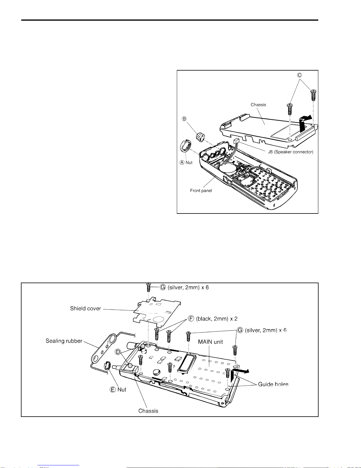
1.14.2 REMOVING MAIN UNIT FROM CHASSIS
Refer to Figure 1-4 and proceed as follows:
1. Remove the sealing rubber around the main unit.
2. Unsolder tabs located at “D”.
Figure 1-3 Chassis Removal
3. Unscrew nut “E”, two black screws “F”, and six
silver screws “G”.
4. Pull the main unit out of the chassis in the direction
indicated by the arrow.
Figure 1-4 Main Unit Removal From Chassis

GENERAL INFORMATION
1-7 Revised July 1999
Part No. 001-7500-002
REVISION SUMMARY
1.15 REVISION SUMMARY
1.15.1 GENERAL
This service manual covers revisions made to the
Falcon™ 751x/754x transceivers through July 1999.
The following information summarizes these
revisions.
1.15.2 SOFTWARE REVISIONS
New Operating Software
Beginning later in 1999, transceivers containing a
new release of operating software will begin shipping.
Transceivers with this new software can be identified
as follows:
•The revision letter in the identification number is
“C” or later (see Section 1.4).
•The operating software is Rev 3.1 or higher. This
number can be determined by selecting Program >
Information using the programming software as
described in Section 3.4.4.
New Programming Software
New programming software is required to
program transceivers with the new operating soft-
ware. This new release is Rev 3.1 or later, and the revi-
sion number is indicated in the upper left part of the
programming screens. Refer to Section 3.1.4 for more
information.
This new software is backward compatible which
means it can also be used to program earlier “A” and
“B” model transceivers.
New Features
•Additional banks can now be programmed. In addi-
tionto2banksx16channels
, 4 banks x 8 channels
or 2 banks of 20 channels + 12 channels can be
programmed.
•The operation of several features has been changed
to improve performance.
•Support has been added for an optional scrambler
and output port. However, those particular options
are not available, so references to them in the
programming software can be ignored. If scram-
bling is desired, use the Transcrypt® scrambler
listed in Table 1-1 instead.
1.15.3 VHF (7510) HARDWARE REVISIONS
C44 (on input of Q32) - With high band (146-174
MHz) models only, changed to 0.0033 µF.
C284 (near output of IC3D) - With high band (146-
174 MHz) models only, changed to 0.001 µF.
R248 (near output of IC3D) - Changed to R119, a
300k-ohm potentiometer. This control is factory preset
and should not require readjustment in the field. Devi-
ation continues to be set electronically as described in
Section 5.4.3
R225 (on output of Q38) - Changed to C292,
0.1 µF.
R258 (100 ohm) - Added in series with pin 22
(AFOUT) of 30-pin output port.
1.15.4 UHF (7540) HARDWARE REVISIONS
R225 (on output of Q38) - Changed to C500, 0.22 µF.
R471 (100 ohm) - Added in series with pin 22
(AFOUT) of 30-pin output port.

GENERAL INFORMATION
1-8
Revised July 1999
Part No. 001-7500-002
7510 (VHF) AND 7540 (UHF) SPECIFICATIONS
The following are general specifications intended for use in testing and servicing this transceiver. For current
advertised specifications, refer to the specification sheet available from your sales representative. Values are
typical and are subject to change without notice. GENERAL
Frequency Range VHF: 136-150 or 146-174 MHz
UHF: 400-430, 440-470, 470-500, or 490-512/520 MHz
Operating Modes Conventional (non-trunked), Tone and digital Call Guard®
Channels 32 maximum
Transmit/Receive Separation Any frequency within the range
Channel Spacing 12.5 kHz (2.5 kHz maximum deviation) or
25 kHz (5 kHz maximum deviation)
Frequency Stability 5.0 PPM from –22° to +140° F (–30° to +60° C)
Dimensions 5.5” x 2.3” x 1.5” (138.5 mm x 58 mm x 37 mm) w/o bat/controls (HxWxD)
Weight 13.8 oz. (390 g) VHF, 14.1 oz. (400 g) UHF (w/ std. bat., antenna, belt clip)
Battery Voltage 9.6 volts DC nominal
Current Drain 60 mA VHF, 65 mA UHF max. (rx standby), 20 mA max. (bat. save mode)
225 mA maximum (receive, 500 mW audio output)
1.0 A maximum (transmit, low power)
2.0 A maximum (transmit, high power)
Battery Life (1050 mAH battery) Low power w/o battery saver - 9.3 hours
(TIA 5-5-90) High power w/ battery saver - 9.6 hours
High power w/o battery saver - 7.3 hours
FCC Compliance Parts 15 and 90
RECEIVER
Sensitivity (12 dB SINAD) 0.25 µV
Selectivity 70dBat25kHz,60dBat12.5kHz
Spurious and Image Rejection 70 dB
Intermodulation 65 dB
Hum and Noise 40 dB
Maximum Frequency Spread Any spread within the range
Audio Power Output 500 mW into 8-ohm load
Audio Distortion Less than 10% at 1 kHz with 60% deviation
Audio Response +2, –8 dB at 6 dB per octave de-emphasis per standard TIA
RF Input Impedance 50 ohms TRANSMITTER
RF Power Output VHF: 5.0W high power, 1.0W low power
UHF: 4.0W high power, 1.0W low power
Spurious and Harmonic Emissions 70 dB
FM Hum and Noise 40 dB at 25 kHz, 34 dB at 12.5 kHz
Audio Modulation 12.5 kHz - 11K0F3E, 25 kHz - 16K0F3E
Audio Distortion Less than 5% at 1 kHz with 40% modulation
Audio Frequency Response +2, –8 dB at 6 dB per octave pre-emphasis per standard TIA
Maximum Frequency Spread Any spread within the band
RF Output Impedance 50 ohms
Duty Cycle (6-6-48 seconds) 10%

2-1 Revised June 1999
Part No. 001-7500-002
TRANSCEIVER OPERATION
SECTION 2 TRANSCEIVER OPERATION
STANDARD MODEL DTMF KEYPAD MODEL
On-Off/Volume
PTT Switch
Microphone
Antenna
Speaker
Channel
Select
Speaker/Mic
Jack
Indicator
Display
Programmable
Keys
Transmit
Charging
Jack
On-Off/Volume
PTT Switch
Microphone
Antenna
Speaker
Channel
Select
Speaker/Mic
Jack
Indicator
Display
Programmable
Keys
Keypad
Transmit
Number
Charging
Jack
2.1 TRANSCEIVER FEATURES
lUp to 32 channels programmable
lMulti-tone and/or Multi-code Call Guard or carrier
squelch programmable
lDTMF encoder and 2/5 tone capability optional
lVHF and UHF models available
lUp to 5 watts (VHF) or 4 watts (UHF) for greater
operating range
lUp to 9.6 hours of battery life with standard 1050
mAH battery pack
lPriority and normal scan to ensure important calls
are not missed
2.2 CONTROLS AND DISPLAY
On-Off/Volume Control - Turns power on and off and
sets the volume level. To adjust the volume for a com-
fortable listening level, refer to the preceding
description.
PTT (Push-To-Talk) Switch - Pushandholdthis
switch to talk, and release it to listen.
Channel Select Keys (▲▼) - Change the selected
channel up or down.
Number Keypad - These keys are on DTMF keypad
models only, and are used to dial telephone numbers,
select channels, and for other functions.
Programmable Switches - The , , , F1-F4,
and A-D can be programmed for various functions (the

TRANSCEIVER OPERATION
2-2
December 1997
Part No. 001-7500-001
A-D keys are available on DTMF keypad models
only). Refer to the descriptions in Section 2.5 for more
information.
Display - Indicates the selected channel, operating
modes, and error conditions.
ChargingJack-Theoptionalwallcharger or cigarette
lighter or DC cables can be plugged into this jack to
charger the battery (see Sections 2.6.7 and 2.6.8).
TransmitIndicator - Lights when the transmitter is on
(PTT switch pressed).
Speaker/Microphone Jack - Connection point for the
optional speaker/microphone and programming cables.
2.3 GETTING STARTED
2.3.1 UNPACKING
The following accessories are included with this
transceiver:
lFlexible antenna
lBelt clip
l1050 mAH battery pack (see Section 2.6)
2.3.2 ANTENNA
The included antenna is screwed into the trans-
ceiver antenna jack as shown below.
2.3.3 BELT CLIP
The belt clip is attached as shown below.
The belt clip is removed as shown below.
2.3.4 TURNING POWER ON
To turn power on, rotate the top panel on-off/
volume control clockwise. To turn it off, rotate it
counterclockwise to the detent. When power is turned
on, a power-up alert tone may sound for about 2 sec-
onds and an opening message may be displayed
(depending on programming). The channel is then dis-
played as an alpha tag or number. The number format
is shown below.
NOTE: If nothing is displayed when power is turned
on, the battery may be discharged or defective. Turn
power off and check the battery. Refer to Section 2.6
for more battery information.
2.3.5 CHANGING CHANNEL
To increase or decrease the selected channel
number, press the ▲or ▼key. If equipped with a
DTMF keypad, you may also be able to select a
channel by entering the number.

TRANSCEIVER OPERATION
2-3 December 1997
Part No. 001-7500-001
2.3.6 ADJUSTING VOLUME
To adjust the volume, rotate the on-off/volume
control while a message is being received. To adjust
while no message is being received, press and hold the
Monitor switch (if programmed, see Section 2.5.6).
This enables background noise for use as a reference
level. Otherwise, note the position of the index on the
knob.
2.4 BASIC OPERATION
2.4.1 RECEIVING A CALL
1. Turn power on and set the volume as described in
Sections 2.3.4 and 2.3.6.
2. Select the desired channel using the ▲▼switches.
The transceiver is now set to receive a message on
that channel.
2.4.2 TRANSMITTING A CALL
CAUTION
Do not transmit without an antenna because trans-
ceiver damage may result. Antenna attachment is
described in Section 2.3.2.
1. Turn power on and set the volume as described in
Sections 2.3.4 and 2.3.6.
2. Wait for the channel to become clear to avoid inter-
ference (see “MONITOR” description in Section
2.5.6).
3. Push and hold the PTT switch on the side and speak
into the microphone at a normal voice level.
NOTE: If a selective calling feature is being used (see
Section 2.4.5), it is recommended that you pause for a
moment before speaking after pressing the PTT
switch. This gives the receiving transceiver time to
detect the call which prevents the possible loss of part
of your first word.
4. Release the PTT switch as soon as your message is
complete so that a response can be received.
2.4.3 LOW BATTERY INDICATION
When a low battery condition is detected, is
displayed continuously. The battery will require
recharging soon.
When battery capacity is nearing the minimum
level needed to operate the transceiver, begins
flashing.
2.4.4 TIME-OUT TIMER
This function disables the transmitter if it is
keyed continuously for longer than the programmed
time. This prevents possible transceiver damage
caused by transmitting for excessive periods and also
a channel from being blocked for an extended period
by an accidentally keyed transmitter.
A penalty timer may also be programmed which
inhibits the transmitter for a fixed time after the time-
out timer is activated.
2.4.5 SELECTIVE CALLING
Introduction
If your transceiver utilizes a selective calling sys-
tem of some type, it may be necessary to select the
particular station to which a call is to be placed or
from which a call is to be received. The general proce-
dure is as follows:
1. Select the transmit code channel or 5-tone code (see
following).
2. Press the switch programmed for the call function.
3. After transmitting a 5-tone code, the remainder of
the call can be carried out in the normal manner.
Transmit Code Channels
Your transceiver may be programmed so that a
transmit code channel is selected when using the call
function just described. To activate this function, press
the switch programmed for transmit code channel
selection. Then enter the number of the desired trans-
mit code channel using the number keypad. The call
+
+

TRANSCEIVER OPERATION
2-4
December 1997
Part No. 001-7500-001
function previously described then transmits the pre-
programmed 5-tone code.
Manual 5-Tone Codes
NOTE: This requires the optional 5-tone unit.
Your transceiver may be programmed to allow
5-tone codes to be sent manually:
1. To activate this function, press the switch pro-
grammed forthe transmit code function. Then enter
the desired transmit code (up to seven digits) using
the number keypad.
2. Activate the call function to transmit the 5-tone
code. Blinking indicates that the keypad entry is
acceptable.
2.5 PROGRAMMABLE FUNCTIONS
2.5.1 GENERAL
The functions described in this section are avail-
able only if they have been programmed. When appli-
cable, they are controlled by the programmable
switches described in Section 2.2. Therefore, the spe-
cific use of each switch varies. The table below can be
filled out and used as a reference to identify the func-
tions that are controlled by these switches.
NOTE: Programming determines the availability of
the following functions. Therefore, a function is avail-
able only if it has been programmed. Refer to
Table 3-2 for more information on these switches.
2.5.2 KEYPAD LOCK
This function disables all keypad keys except the
one used to control this feature. This prevents keys
from being accidentally pressed. Some channels may
be programmed so that this feature is not available. To
toggle this function, press for 1 second the switch pro-
grammed for the Keypad Lock function. The keypad
is locked when the key icon ( ) is displayed.
2.5.3 PRIORITY CHANNEL
This function is used to quickly select a prepro-
grammed priority channel. When the switch pro-
grammed for this function is pressed, “PRIO” is
briefly displayed and the priority channel is automati-
cally selected.
2.5.4 SCAN
The scan feature monitors a preprogrammed
group of channels. When a signal is detected that the
transceiver is programmed to receive, scanning stops
and the message is received. Shortly after the mes-
sage is complete, scanning resumes. To turn scanning
on and off, press the switch programmed for Scan. A
message may be displayed while scanning.
“Lockout Scan” (preprogrammed list scan) or
“Priority Scan” can be preprogrammed. When the
“Power-Save” function is activated, the transceiver
checks all preprogrammed channels and then returns
to the power save mode.
2.5.5 KEY BEEP
The function provides a confirmation tone when
keys are pressed. To turn this feature on and off, press
the switch programmed for the Beep function for
1 second or longer.
2.5.6 MONITOR
The Monitor function allows the transceiver to be
manually unsquelched to determine if a channel is
busy. Channels may be programmed so that either all
messages or only those messages intended for you are
received. Therefore, if you hear only your messages,
the channel must be monitored before transmitting to
makesuresomeoneelseisnotusingit.Ifyouwereto
transmit while someone else is talking, you would
probably disrupt their conversation.
To enable monitoring, press the switch pro-
grammed for the Monitor function. If the channel is
Option Switch Functions
F1 A
F2 B
F3 C
F4 D

TRANSCEIVER OPERATION
2-5 December 1997
Part No. 001-7500-001
programmed so all messages are heard, press and hold
the switch to hear all messages. If only messages
intended for you are heard, press the switch momen-
tarily to select the audible condition.
2.5.7 TALK-AROUND
Your transmissions may go through a base station
(such as a repeater). In this case, if you are out of radio
range of the repeater, you will not be able to contact
anyone on that channel even though the transceiver
you are calling may be only a short distance away.
The talk-around function allows you to contact
these transceivers directly without going through a
repeater. To activate the talk-around function, press
andholdfor1secondtheswitchprogrammedforthis
function. Then to turn if off again, press this switch
momentarily.
2.5.8 DTMF TRANSMISSION
This function allows you to transmit a prepro-
grammed DTMF code to perform actions such as con-
trolling a repeater or opening the squelch of another
transceiver. Proceed as follows:
Manual Transmission - Enter the desired digits using
the number keypad while pressing the PTT switch. The
transceiver may also be programmed so that it is not
necessary to press the PTT switch to transmit the digits.
Automatic Preprogrammed Transmission -Pressthe
switch programmed for DTMF transmission. Then
press the ▲▼switches to select the desired channel.
Then press the DTMF switch again to send the DTMF
code.
2.5.9 DTMF REDIAL
This function allows the last-used DTMF code to
be retransmitted by simply pressing a key. To activate
this feature, press the switch programmed for the
DTMF Redial function. If no code has been transmit-
ted since power was turned on, this feature is not
available.
2.5.10 HIGH/LOW POWER OUTPUT
This function selects high or low power output on
the current channel. To toggle between high and low
power, press the switch programmed for High/Low
Power. When low power is selected, “LOW” is
displayed.
2.5.11 EMERGENCY OPERATION
The emergency function allows you to quickly
and easily send your ID in case of emergency. To acti-
vate this function, press and hold for 1 second the
switch programmed for Emergency.
lA preprogrammed channel is then selected and the
emergency code automatically sent.
lThe preprogrammed channel remains selected until
the control signal is received back or power is
turned off.
lThe emergency call is repeatedly transmitted at a
preprogrammed interval.
2.5.12 DISPLAY LIGHTING
The display backlight has three operating modes:
OFF -No backlight is available
AUTO -When any key is pressed, the backlight turns
on for 5 seconds.
CONTINUOUS -The backlight is on continuously
when power is on.
2.6 BATTERY INFORMATION
2.6.1 BATTERY PACK REPLACEMENT
NOTE: Before replacing the battery pack, transceiver
power MUST be turned off by the top panel on-off/
volume control.
To remove the battery pack, push and hold the
release button and then pull the top of the battery pack
outwards (see following). To attach the battery pack,
place the notched end onto the transceiver and press
the top toward the transceiver until it clicks into place.

TRANSCEIVER OPERATION
2-6
December 1997
Part No. 001-7500-001
BATTERY CAUTIONS
NEVER incinerate used battery packs because they
may explode.
NEVER immerse the battery pack in water. If the bat-
tery pack becomes wet, be sure to wipe it dry BEFORE
attaching it to the transceiver.
NEVER short the terminals of the battery pack. In ad-
dition, do not place a pack where nearby metal objects
could touch the contacts. The resulting current flow
could cause excessive heat or fire.
2.6.2 MISCELLANEOUS BATTERY
INFORMATION
Memory Effect
If the battery pack has very little capacity after
being charged, completely discharge it by leaving
transceiver power on overnight. Then fully recharge
the pack again. If it still lacks capacity or does not
retain a charge, it must be replaced with a new pack.
Recycling
The rechargeable battery pack used with this
transceiver is recyclable. It is usually illegal to dispose
of nickel-cadmium batteries in the municipal waste
stream. Contact local authorities for information on
how to properly dispose of nickel-cadmium battery
packs.
2.6.3 USING BATTERY CASE
If using optional Battery Case, Part No. 587-
7500-120, install eight AA size alkaline or nickel-cad-
mium batteries as shown in the following illustration.
BATTERY CASE CAUTIONS
lIf using nickel-cadmium batteries, make sure all
cells are the same brand, type, and capacity. Never
mix old and new cells. Failure to observe these pre-
cautions may cause a fire hazard or transceiver
damage.
lIf using alkaline or other dry cell batteries, NEVER
connect DC power to the transceiver. This always
charges the installed batteries and will damage the
transceiver.
lWith all types of batteries, NEVER incinerate the
batteries because an explosion could result. Also,
NEVER expose a detached battery case to water. If
it does get wet, be sure to wipe it dry before using.
2.6.4 BATTERY CHARGING INFORMATION
CAUTION
Be sure to turn the transceiver off while charging or
removing the battery pack. Failure to do so may
damage the transceiver.
Prior to using the transceiver for the first time,
the battery pack must be charged fully in order to pro-
vide optimum life and operation. Follow these precau-
tions when charging the battery pack:
lRecommended ambient temperature when recharg-
ing is +50° to +104° F (+10° to +40° C).
lUsethesuppliedchargeroroneof theoptionalrapid
chargers. NEVER use other manufacturers’
chargers.
lTheoptionalDCcableorcigarettelightercable(see
Section 2.6.8) may be used as a charger power

TRANSCEIVER OPERATION
2-7 December 1997
Part No. 001-7500-001
source instead of the AC adapter supplied with the
desktop charger (see following).
2.6.5 USING DESKTOP CHARGER
The optional desktop charger shown below is
available in the following versions. These chargers
include all required items including the AC adapter,
base, and battery spacer.
120 VAC Model - Part No. 585-7500-011
230 VAC Model - Part No. 585-7500-012
CAUTION
Turn transceiver power off while charging. Failure to
do so will result in incorrect charging and may result
in reduce battery life. The transceiver cannot be used
even if power is turned on.
Install the included spacer as shown in the fol-
lowing diagram. Charge time for the 1050 mAH bat-
tery is approximately 2.0 hours. The charge indicator
displays the following conditions:
Steady Orange - Charging is occurring
Steady Green - Charging is complete
Flashing Orange - Input voltage low. Check power
source.
Flashing Red - Problem with battery pack or charger.
Reinsert battery or try different pack. If problem
persists, the charger may be defective.
2.6.6 USING MULTI-UNIT CHARGER
The multi-unit charger is shown in the following
illustration. Each charger slot functions like the desk-
top charger described in the preceding section. There-
fore, the “Caution”, charge time, and indicator opera-
tion in that section also apply when this charger is
used. As indicated in Table 1-1, the power supply is
not included with the base and must be ordered
separately.
2.6.7 USING WALL CHARGER
The optional wall trickle charger shown in the
following illustration is available in the following ver-
sions.
120 VAC Model - Part No. 585-7500-001
230 VAC Model - Part No. 585-7500-002
This charger plugs directly into the transceiver as
shown below. Approximate charge time is 15 hours.
Observe the following precautions when using
the wall charger:
lCharge only nickel-cadmium batteries. NEVER
connect this charger to the transceiver when the op-
tional battery case is being used with alkaline or
other dry cell batteries installed. Attempting to
charge these batteries may damage the transceiver
or batteries.
Spacer Installation
Charging w/Transceiver Charging w/o Transceiver
Power
Supply
Charge Indicators
(Each Slot Functions
Independently)
Multi-Unit Charger

TRANSCEIVER OPERATION
2-8
December 1997
Part No. 001-7500-001
lDo have transceiver power turned on when this
charger is used. The charge current is insufficient to
operate the transceiver and charge the battery pack.
2.6.8 USING OPTIONAL CABLES
Optional Cigarette Lighter Cable, Part No. 585-
7500-027, or DC Power Cable, Part No. 585-7500-
029, can be used to charge the transceiver similar to
the wall charger just described. A DC voltage source
of 12-16 volts is required when these cables are used.
Connect these cables to the charge jack on the side as
shown in the following illustration.
Observe the following precautions when using
either of these charging cables:
lCharge only nickel-cadmium batteries. NEVER
connect this charger to the transceiver when the op-
Plug Into
Charge
Jack
Wall Charger
Cigarette Lighter Cable
DC Power Cable
(+) White
(–) Black
To 12-16 VDC
Power Source
Plug Into
Charge
Jack
tional battery case is being used with alkaline or
other dry cell batteries installed. Attempting to
charge these batteries may damage the transceiver
or batteries.
lEven if the power source has enough current capac-
ity, the Charge jack can be used only for charging
purposes. Do not attempt to operate the transceiver
with a charger connected to this jack if a battery is
not attached.
lChargingcontinuesevenafterthebatteryisfully
charged. Therefore, do not charge a battery for
extended periods because overcharging will
result.
2.6.9 REPLACEMENT BATTERY PACK
Replacement Battery Pack, Part No. 587-7500-
105, is the same pack that was included with the trans-
ceiver when it was new. It is a nominal 9.6V pack con-
taining rechargeable nickel-cadmium batteries that
have a capacity of 1050 mAH. Under standard operat-
ing conditions (duty cycle of 5% transmit, 5% receive,
90% standby), typical transceiver operating time with
a fully charged pack is as follows:
High Tx Power/battery save mode - 9.2 hours
Low Tx Power - 8.8 hours
Charge a new battery pack before it is used. For
maximum battery life, observe the following
precautions:
lAvoid overcharging. Do not charge a battery pack
for longer than 48 hours.
lUnder normal conditions, use a pack only until the
low-battery indication appears (see Section 2.4.3).
Do not regularly use a pack until the transceiver is
totally inoperative.
When the operating time of a fully charged bat-
tery becomes extremely short or a pack fails to hold a
charge, replace the battery pack with a new one. Refer
to Section 2.6.1 for more battery pack information.
This manual suits for next models
1
Table of contents
Other E.F. Johnson Company Two-way Radio manuals

E.F. Johnson Company
E.F. Johnson Company Challenger 7171 User manual

E.F. Johnson Company
E.F. Johnson Company 761X User manual

E.F. Johnson Company
E.F. Johnson Company 001-9800-200 User manual

E.F. Johnson Company
E.F. Johnson Company 7780 Series User manual

E.F. Johnson Company
E.F. Johnson Company 7700 Series User manual


