E-TEN glofiish x800 Operating manual

Copyright © 1985~ 2007, E-TEN Information Syst ms Co., Ltd. All Rights R s rv d.
1
T
T
Te
e
ec
c
ch
h
hn
n
ni
i
ic
c
ca
a
al
l
l
S
S
Se
e
er
r
rv
v
vi
i
ic
c
ce
e
e
M
M
Ma
a
an
n
nu
u
ua
a
al
l
l
f
f
fo
o
or
r
r
C
C
Cu
u
us
s
st
t
to
o
om
m
me
e
er
r
r
glofiish®
X800
Rev 1.1
August 10, 2007
E
ET
TE
EN
N
I
In
nf
fo
or
rm
ma
at
ti
io
on
n
S
Sy
ys
st
te
em
m
C
Co
or
rp
p.
.

Copyright © 1985~ 2007, E-TEN Information Syst ms Co., Ltd. All Rights R s rv d.
2
TABLE OF CONTENTS
CHAPTER 1 I
NTROD CTION
·····································································································3
CHAPTER
2 P
ROD CT
S
PECIFICATION
······················································································4
2.1 P
ROD CT
S
PECIFICATION
·················································································4
2.2 O
VERVIEW OF
S
RFACE
··················································································6
CHAPTER
3
T
OOLING FOR
R
EPAIR
····························································································7
CHAPTER
4
M
ODE
S
WITCHING
··································································································8
CHAPTER
5
D
IAGNOSTICS
········································································································ 9
5.1 PDA B
ILD
-
IN
D
IAGNOSTIC
P
ROGRAM
···························································· 9
5.2
O
THER
F
NCTION
T
EST
NDER
OS ······························································· 11
CHAPTER
6 D
ISASSEMBLING
·································································································12
CHAPTER
7
A
SSEMBLING
······································································································· 20
CHAPTER
8
S
PARE
P
ARTS
L
IST
······························································································28
8.1 S
PARE
P
ARTS FOR
R
EPAIR
···········································································28
8.2
A
CCESSORY
L
IST
·························································································32
CHAPTER
9
S
OFTWARE
PGRADE
··························································································33
9.1 S
YSTEM
R
EQ IREMENT
·················································································33
9.2 S
OFTWARE
PGRADE
S
TEPS
········································································33
CHAPTER
10
D
EFINITION OF
S
ERIAL
N
MBER
··········································································34
CHAPTER
11
I
NSPECTION
C
RITERIA
(LCM) ·············································································35
ANNEX R
EVISION
H
ISTORY
·····································································································36

Copyright © 1985~ 2007, E-TEN Information Syst ms Co., Ltd. All Rights R s rv d.
3
CHAPTER 1. INTROD CTION
This manual provides technical information necessary to maintain and support repair
service of Pocket PC Phone glofiish
®
X 00. Information contained in this document is
copyrighted by E-TEN Information Systems Co., Ltd. It is intended for use of E-TEN’s
authorized service providers and clients. Service technicians may reproduce this document as
needed for repair uses only. Reproduction for any other activities may be illegal to copy certain
materials without permission, including documents and images. If you are not sure whether you
have permission, seek legal advice.
Every effort has been made to keep the information contained in this document current
and accurate as of the date of revision. However, no guarantee is given to error-free and may
include technical inaccuracies or typographical errors. Changes are periodically made to the
information herein; these changes will be incorporated in later editions. Improvements or
changes in the product designs or the specifications described may be made at any time.

Copyright © 1985~ 2007, E-TEN Information Syst ms Co., Ltd. All Rights R s rv d.
4
CHAPTER 2. PROD CT SPECIFICATION
2.1 Product Specification
Operating System Windows Mobile™ 6.0 for Pocket PC Phone Edition
Processor Samsung SC3 2442, 500MHz
Memory 64MB RAM, 256MB ROM
Display 2. " VGA, 65,536 colors TFT-LCD touch panel ( Resolution : 640 x 4 0 )
Dimensions 113.5 (L) x 60.5 (W) x 15. (H) mm
Weight 147 g ( including Battery & Stylus )
Communications
HSDPA / UMTS ( 2100/1900/ 50 MHz )
Quad-Bands GSM:50/900/1 00/1900 MHz
EDGE class 10/GPRS class 10
Bluetooth 2.0 class 2 + EDR
WiFi IEEE 02.11b/g Certificated
GPS Embedded Chip, SiRF Star III
Camera 2M pixels Auto-Focus with flashlight, up to 1600x1200 resolution
0.3M pixels Fixed-Focus Camera for conference call usage
Expansibility micro SD slot
Interface/ Audio Built-in microphone and speaker, external stereo headset jack.
Interface/ Data miniUSB Sync
Ergonomic Design
1. Touch Panel for stylus or fingertip
2. Buttons :
- Joystick navigation key
- Power button
- Camera shoot key
- Reset button
- Record button
- Volume control key
- Send/End key

Copyright © 1985~ 2007, E-TEN Information Syst ms Co., Ltd. All Rights R s rv d.
5
- Quick Application key x 6 ( Right Softkey / Left Softkey / GPS hotkey / M-desk
hotkey / OK / Start )
Battery 1530 mAh Li-Poly, rechargeable & replaceable
Power
DC Adaptor, 5V1A,
LED Indication
<< Right-Up side: Red, Green >>
- Red always light: Device is charging
- Red sparkling once every 4 sec: Warning of Battery low level
- Red sparkling twice repeatedly: Warning of Battery critical situation.
- Red sparkling continuously: Battery cover not on or Battery level very low.
- Green always light: Battery charging is full
- Green sparkling once every 4 sec: GSM is connecting on line
<< Lift-Up side: Blue, Amber & White >>
- Blue sparkling once every 4 sec: BlueTooth enable
- Amber sparkling once every 4 sec: WLAN enable
- White sparkling once every 4 sec: GPS enable
Add-on Applications
1. E-TEN Application Value Pack
2. E-TEN Application Value Pack for Multimedia
3. E-TEN Application Value Pack for Phone
4. MMS Composer* (*subject to change by region)
5. Voice Recognition* (*subject to change by region)
Accessories
(Optional) Standard Battery pack / Car-Charger / Car-Mount / Bluetooth Headset.
Certification CE / R&TTE / DGT / FCC /BQB / WiFi /USB-IF/ NSTL-LTK

Copyright © 1985~ 2007, E-TEN Information Syst ms Co., Ltd. All Rights R s rv d.
6
2.2 Overview
○
1
Volume Adjustment
○
11
Left Soft-Key
○
21
Power key
○
2
Recorder key
○
12
Right Soft-Key
○
22
Camera shoot key
○
3
Reset key
○
13
M-Desk
○
23
2M AF Camera Lens
○
4
Headset Jack
○
14
Send / Hang on Contact list
○
24
Mirror
○
5
VGA Camera
○
15
Start Hot-Key
○
25
Flashlight LED
○
6
Receiver
○
16
Joystick Navigation key
○
26
Speaker hole
○
7
BT /WLAN /GPS active LED
○
17
OK Hot-Key
○
27
Battery Cover
○
Power / Phone active LED
○
1
End / Hang up
○
2
PDA Stylus
○
9
Display w/ Touch Panel
○
19
Micro SD slot
○
10
GPS Hot-Key
○
20
Mini-USB connector

Copyright © 1985~ 2007, E-TEN Information Syst ms Co., Ltd. All Rights R s rv d.
7
CHAPTER 3. TOOLING FOR REPAIR
Item Purpose
Cleaning Wipers
T5 Screwdriver
Tweezers
Plastic Stick
Disassembly & Assembly
Blower
Soft Brush
Camera Lens Clean
Mini USB Cable / Cradle Synchronization Test to PC
Micro SD Card SD Read / Write Test
Headset Headset Audio / Recording / FM Test
AC Adapter
Battery
Charging
Software Upgrade tools Software Upgrade (EUU, ActiveSync)
GSM / 3G(HSDPA/UMTS) SIM
Card
Bluetooth Headset
Phone Function Live Test
Barcode Label Printer IMEI Sticker Printing

Copyright © 1985~ 2007, E-TEN Information Syst ms Co., Ltd. All Rights R s rv d.
8
CHAPTER 4. MODE SWITCHING
Function Procedure
Hardware Reset 1. Press and hold POWER button
2. Press RESET button and release both
(power & reset) buttons at the same time
Software Reset Press RESET button
Testing (Build-in) Program 1. Press and hold CAMERA button
immediately after doing a hardware reset
2. Release CAMERA button after the
testing program shows up on the LCD
Clean-boot Option 1. Press and hold END button immediately
after doing a hardware reset
2. Release END button after the clean boot
option screen shows up on the LCD
Download Mode 1. Press and hold RECORD button
immediately after doing a hardware reset
2. Release RECORD button after the
USBDL screen shows up on the LCD

Copyright © 1985~ 2007, E-TEN Information Syst ms Co., Ltd. All Rights R s rv d.
9
CHAPTER 5. DIAGNOSTICS
5.1 PDA Build-in Diagnostic Program
How to entering the program:
a. Press and hold POWER button
b. Press RESET button and release both buttons at the same time
c. Press and hold CAMERA button immediately after having hardware reset (above 1 & 2)
d. Release CAMERA button after the screen shows up
NOTE. Always tap the up-right corner [x to exit when finished.
Item Description Procedure / Criteria
NFlash NAND Flash test Tap screen if result is “Test O.K.- Bad Block =0”.
Tap up-right corner to exit
RAM SDRAM test Tap screen if result is “All are O.K.”
Tap up-right corner to exit
Keypad Pad Test
Follow the instruction and press GREEN hinted button in
order.
Tap up-right corner to exit if passed all pad test
X 00 Test System
╳
╳╳
╳
▲
1.NFlash 2.RAM
3.Keypad 4.T Panel
5.AUDIO 6.LCD
7.BackLight
.LED
9.Vibrator 10.BAT Chip
11.Battery 12.SD/MMC
13.Camera 14.OS IMG
15.Bluetooth
16.GPS
17.GSM 1 .FM Test
19.B&E Info
20.X Packet
▼
Copyright © 1985~ 2007, E-TEN Information Syst ms Co., Ltd. All Rights R s rv d.
10
T Panel Touch Panel test Take stylus pen then draw few lines slowly around the screen
rims and center.
*Breaking lines and screen can’t alignment are not allowed.
Tap up-right corner to exit
AUDIO Voice record/reply test
1. Tap Recording icon and talk to the microphone for 1-2 sec,
the voice will reply the recorded sound automatically.
2. Plug your headset and run the record/reply test again.
3. Tap Receiver, and tap “PASS” after hear a tone by phone
generated.
Tap up-right corner to exit
LCD LCD color test Tap screen repeatedly. Check color screen if normal or any
defective pixels on it.
Tap up-right corner to exit
BackLight LCD backlight test Tap “Back Light On/Off” and tap “scroll up/down” to test
backlight.
Tap up-right corner to exit
LED LED indication test Tap “ALL ON” then “ALL OFF”
to check all indicative color LED
turns on/off, and tap PASS.
Tap up-right corner to exit
Vibrator Vibration testing Select “Vibrator On then Off” to check if device is vibrating.
Tap up-right corner to exit
BAT Chip main battery test Test main battery calibration.
Tap up-right corner to exit if screen shows PASS
Battery Test battery switch
function
Follow the procedures and check screen shows “PASS!”
Tap up-right corner to exit
B&E Info Read SW version Tap “Read SW Version”, check the system software and
language version.
Tap up-right corner to exit

Copyright © 1985~ 2007, E-TEN Information Syst ms Co., Ltd. All Rights R s rv d.
11
5.2 Other Function Test Under OS
Testing Item Procedures Guidelines
Phone Live
Test
Test dial and receive phone calls
1. Using Device over device to test
2. Using Headset to answer a call
3. Using Bluetooth to answer a call
Check Dial/Receive phone call’s voice is
clear enough
USB connection
Synchronize PDA with PC Connected USB to check PDA can be
communicate with PC’s ActiveSync
Camera with
Micro SD card
Read/Write Test
Snap shot a photo then delete and save
the file in Micro SD card
1. Check Camera function and photo
appear normal
2. Check read, write & delete the saved
file for Micro SD card
1. Enable Wireless
2. Execute Internet Explore to check if
the Wireless LAN works well
Must be able to open a website WiFi Test
Note: Problems regarding to Firewall and set Proxy, please contact your IT specialists
GPS Test 1. Execute the AP as GPS Viewer
2. Check the contents of AP
Satellite searching status
1. No time limitation
2. Fix: 3D Fixed
Power
consumption
Test
1. Turn off power button, check SI
2. Execute program “2577” under OS
3. Select Backlight ON and OFF to test
TI
4. Finally select Clean Boot to
Tool:
1. Dummy battery
2. Dummy battery cover
3. Power supply
4. Micro SD card
SI: current ≦10mA
TI: Backlight ON (GSM/BT/WLAN/GPS
ALL OFF) current ≦250mA
TI: Backlight OFF (GS /BT/WLAN/GPS
ALL OFF) current ≦100mA

Copyright © 1985~ 2007, E-TEN Information Syst ms Co., Ltd. All Rights R s rv d.
12
CHAPTER 6. DISASSEMBLY
P/N
*Quick Ref. Figure Reading Sequences
Main nit
Battery Cover & Stylus & Battery, SIM Card(
((
(if has)
))
)
P/N: 49005120
40009520
40009510
A. Remove battery-cover from the unit, bottom side go first.
B. Pull out the Stylus.
C. Removing battery from the unit by tools, release both latches.
D. Finish.
A B
C D
E F

Copyright © 1985~ 2007, E-TEN Information Syst ms Co., Ltd. All Rights R s rv d.
13
Main Bracket Assy
Antenna Cover Assy P/N: 64041640
A. Use plastic-stick to insert the latch hole, dig it up with a little strength.
B. When fin
ished, taking care of the other side as well. Unlock all latches and remove Cover from
the bracket.
C. Finish.
TIPS. Always the bottom go first, or you will hard to get this part disassembled at the end.
Caution!! The surface of the Cover easily been cut or get injury, do not use any sharp tools get the help.
Copyright © 1985~ 2007, E-TEN Information Syst ms Co., Ltd. All Rights R s rv d.
14
Main Bracket Assy
Front Cover Assy(
((
(unscrew needed)
))
) P/N: 44001160*2

Copyright © 1985~ 2007, E-TEN Information Syst ms Co., Ltd. All Rights R s rv d.
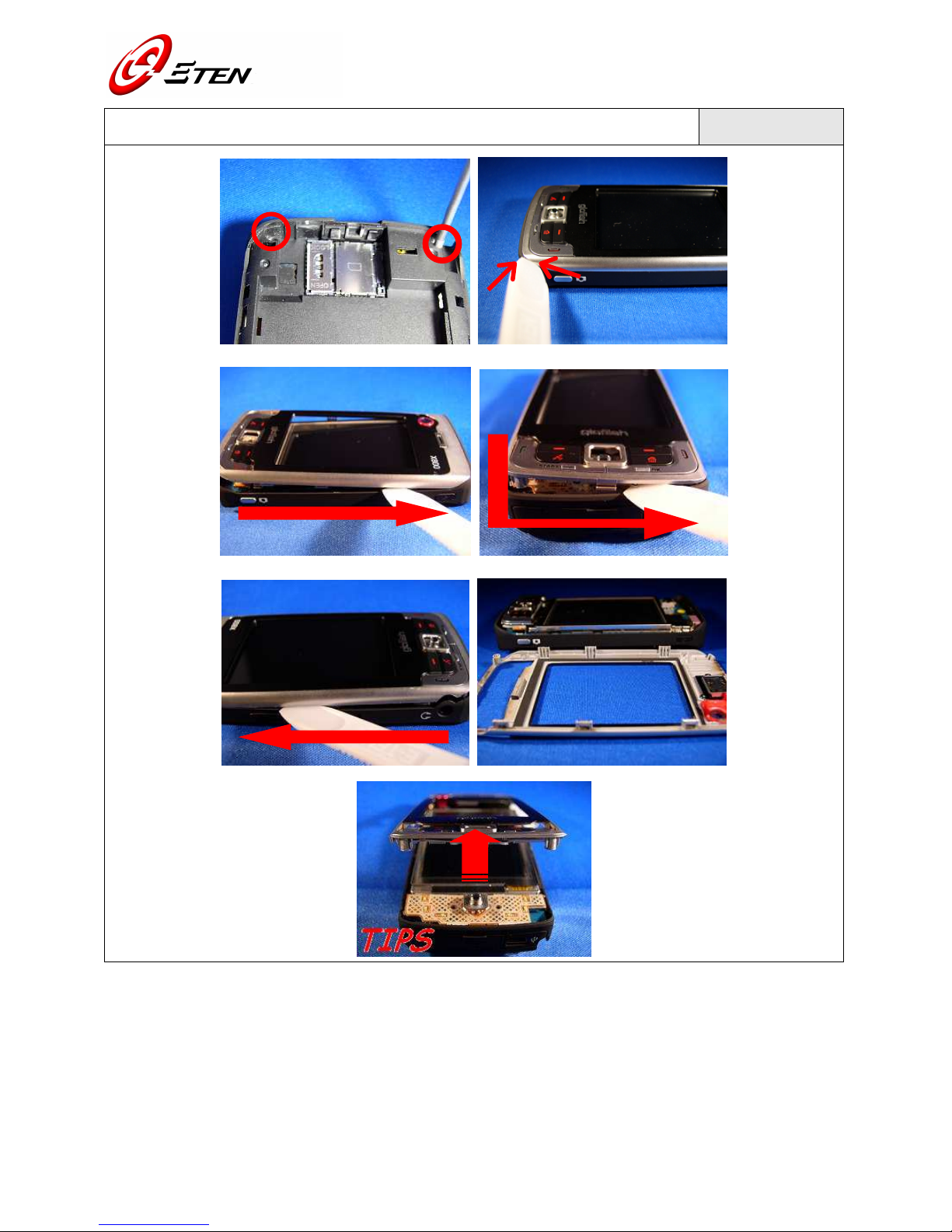
15
A. Two screw holes are at bottom of the unit. Use T5-screwdriver to unscrew them both.
B. Use plastic-stick to pick a hole near the camera-button, dig it up by using a little strength.
C. Sliding stick to the top of cover, separate them from the bracket.
D. Sliding through bottom case by the same way.
E. Slightly move it along to the top, nicely to lifts the Cover up and remove it from the bracket.
F. Finish.
TIPS. Always the bottom go first, or you will hard to get this part disassembled at the end.
Caution!! Do not use over strength to do the works, other parts would be damaged when using the sticker.
Front Cover Assy
Receiver P/N: 64041650
490052 0
A. Remove receiver by using tweezers. Or, tapping it out by fingers.
B. Finish.
M/B
Keypad Module Assy P/N: 40010600

Copyright © 1985~ 2007, E-TEN Information Syst ms Co., Ltd. All Rights R s rv d.
16
A. Use plastic-stick to digging gap with a little strength, nicely to pick the Keypad Module up.
B. Bending FPC to the opposite way. Unlock connector from socket by using tweezers.
C. Finish.
Caution!! Use tweezers in an ease way to get the helps. The FPC Assy or other parts could be damaged by
tools misusage.
Main Bracket Assy
M/B(
((
(unscrew needed)
))
) P/N: 44001160*2

Copyright © 1985~ 2007, E-TEN Information Syst ms Co., Ltd. All Rights R s rv d.
17
A. Two screw holes at top of the unit. Use T5-screwdriver to unscrew them both.
B. Use plastic-stick digging M/B a little out from the top corner of bracket.
C. Hold the unit and make it straight on the desk.
D. Use two hands to apart the M/B from the bracket, smoothly to get it out from the mini USB port.
E. Next the headset port.
F. Slightly take the M/B out when released.
G. Finish.
TIPS. Follows “mini USB” then “headset” port in an order.
Main Bracket Assy
Speaker & Vibrator, Rubber Reset Key
P/N: 40009410
49005290
49005260
43001070

Copyright © 1985~ 2007, E-TEN Information Syst ms Co., Ltd. All Rights R s rv d.
18
A. Pulling out Speaker from bracket with the hook side of plastic-stick.
B. Pick Vibrator out from bracket by using tweezers.
C. Pick key rubber up from the bracket.
Note. Removing the tape as clean as possible and make it ready for the new parts on the bracket.
M/B
Rubber MIC & Shielding Camera, Camera 2M
P/N: 64041620
43001060
41002670
03040220
A. Peel off Rubber from the MIC.
B. To get a lifting point along shielding edge by using Tweezers. Both side
s should get the balance
strength to picking it up.
C. Unlock CAMERA connector from the socket of M/B.
D. Finish.

Copyright © 1985~ 2007, E-TEN Information Syst ms Co., Ltd. All Rights R s rv d.
19
M/B
LCM & Shielding LCM P/N: 02000670
41002650
A. Unlock LCM connector on the M/B.
B. Release all shielding latches along the edge of M/B.
C. Pick M/B up from LCM shielding, handle with care if you were caught it by hands.
D. Unlock latches beside the LCM, get apart LCM from the shielding.
E. Finish.
Note. Move or sliding the LCM with care, it can be easily damaged by indiscreet disassembly.

Copyright © 1985~ 2007, E-TEN Information Syst ms Co., Ltd. All Rights R s rv d.
20
CHAPTER 7. ASSEMBLY
P/N
*Quick Ref. Figure Reading Sequences
LCM & Shielding LCM
M/B
P/N: 02000670
41002650
64041620
A B
C D
E F
Table of contents


