EarthLinked HCM-1836C User manual

HCM-410CP-IM (12/15) Copyright 2015 Earthlinked Technologies, Inc
Hybrid Cooling Module
Models HCM-1836C and HCM-4272C
Installation Manual
for R-410A
CONTENTS
PAGE
Pre-Installation
3
Installation
5
Placement
5
Refrigerant Connections
7
Electrical and Start-Up
9
Fan Speed Control
10

HCM-410CP-IM (12/15) Page 2
Disclaimer
The EarthLinked®Hybrid Cooling Module is sold as a system component part and must be properly
sized and matched to the system compressor unit to provide the intended performance and safe
operation of the system. This component must be installed and serviced by an ETI authorized
technician. Installation and service must be made in accordance with the instructions set forth
within this manual.
Failure to provide installation and service by an ETI authorized technician in a manner consistent
with this manual will void the limited warranty coverage for the EarthLinked® system.
EarthlinkedTechnologies shall not be liable for any defect, unsatisfactory performance, damage or
loss, whether direct or consequential, relative to the design, manufacture, construction, application
or installation of other components in the EarthLinked® system.
Earthlinked Technologies, Inc.
4151 South Pipkin Road
Lakeland, Florida 33811
tel. 863-701-0096 ● fax 863-701-7796
info@earthlinked.com ● www.earthlinked.com

HCM-410CP-IM (12/15) Page 3
Pre-Installation
This Hybrid Cooling Module (HCM) is sold as a system component and must be properly matched
with the compressor unit to provide the anticipated performance and safe operation of the system.
The table below lists the properly matched EarthLinked®Hybrid Cooling Module models with
EarthLinked®compressor unit models.
If the HCM is installed as a retrofit, the refrigerant charge in the existing system must be
recovered before HCM installation. Use new refrigerant to recharge the system.
Application of the Hybrid Cooling Module (HCM) to EarthLinked®systems will require the
use of two (2) field supplied Type ACR copper couplings to match the HCM with the line set
vapor tube size. See the table below to determine the required coupling sizes.
COMPRESSOR UNIT/HCM MODEL MATCH
Compressor
Unit Model
Hybrid Cooling Module
Vapor Line Set Size,
OD, in.
Model HCM
Connections
OD, In.
R-410A
-018
-1836C
7/8
5/8
-024,-025
5/8
-030
3/4
-036
3/4
-040
3/4
-042
-4272C
1-1/8
3/4
-048
7/8
-050
7/8
-054
7/8
-060
7/8
-066,-068
1-1/8
-072
1-1/8
.
WARNING!
Before installing this Hybrid Cooling Module (HCM), be sure that all electrical
power to the EarthLinked® system is “OFF”. Wear adequate protective
clothing and practice all applicable safety precautions within installating this
equipment. Failure to do so may result in equipment and/or property damage,
personal injury or death.
IMPORTANT!
This EarthLinked® Hybrid Cooling Module (HCM) is for use with EarthLinked®
space heating and cooling systems that provide cooling. The HCM is a
required component of the EarthLinked® systems where indicated in the
EarthLinked® Performance Tables for R-410A systems.

HCM-410CP-IM (12/15) Page 4
The dimensions data for the Hybrid Cooling Module is shown in Figure 1.
Dimensions,
Inches
Connections
Tube, OD,
inches
Sound,
dB(A)
Net
Weight,
Lbs
Coil
H
W
D
Inlet
Outlet
Rows
Fins/inch
Face Area,
Sq Ft
25-7/8
36
17-3/8
7/8
7/8
52.0
95
2
15
7.0
Fan
Electrical
Type
CFM
RPM
Dia., inches
Power
Fan HP
Fan FLA
Min Voltage
Swept
1,800
810
20
230-1-60
1/6
1.0
207
Figure 1. Hybrid Cooling Module Dimensions and Data

HCM-410CP-IM (12/15) Page 5
Installation –Hybrid Cooling Module Placement
The Hybrid Cooling Module unit is placed as shown in Figure 2 relative to other components in the
EarthLinked®system. The Hybrid Cooling Module is located outdoors and will be connected
to the refrigerant line set (vapor tube) outside the building.
Figure 2. Hybrid Cooling Module Placement in EarthLinked®System
Location Requirements for the Hybrid Cooling Module:
1. Within 20 Feet of the earth loop line set. Minimize refrigerant line lengths.
2. No more than 20 feet higher than the earth loop manifolds.
3. With proper clearances around the unit:
24 inches minimum on the two sides and back (coil side)
36 inches minimum on the front (fan side)
4. Away from windows, patios, decks, etc., where unit operation sounds may disturb the
occupants.

HCM-410CP-IM (12/15) Page 6
5. On a solid, level mounting pad. The mounting pad should extend a minimum of 2 inches
beyond the cabinet size of the Hybrid Cooling Module. The minimum pad size is to be 22
inches by 46 inches. The pad should NOT be in contact with or be an integral part of the
building foundation. The following DiversiTech Pads (or their equivalent) are recommended.
The standard pads are 2inches thick. Local building codes may require a 3 inch thick pad.
Model Number
Size, Inches
Comments
Ultralite®UC2448-2
24 x 48 x 2
Fiber-cement construction
Ultralite®UC2448-3
24 x 48 x 3
Fiber-cement construction
Elite®EL3648-2
36 x 48 x 2
Plastic-drillable for securing
unit
Elite®EL3648-3
36 x 48 x 3
Plastic-drillable for securing
unit
6. Where conditions or local codes require the Hybrid Cooling Module to be attached to a
mounting pad or frame, tie down bolts should be used to fasten through the holes provided
in the Hybrid Cooling Module feet.
7. Elevate the Hybrid Cooling Module per local climate and code requirements to provide
clearance above estimated snowfall level and ensure adequate water drainage of Hybrid
Cooling Module. Use snow stand in areas where prolonged freezing temperatures are
encountered.
Do NOT Locate the Hybrid Cooling Module:
1. On brick, concrete blocks or unstable surfaces
2. Near clothes dryer exhaust vents
3. Near sleeping area or near windows
4. Under eaves where water, snow or ice can fall directly in the unit
5. Within clearance less than 2 Feet from a second unit
6. Within the minimum distance the Hybrid Cooling Module can be installed from the property
line, where local zoning ordinances apply.

HCM-410CP-IM (12/15) Page 7
Installation –Refrigerant Connections
The Hybrid Cooling Module has two refrigerant connections on the service side of the unit as shown
in Figure 1. The connections are the same size as each other. Each connection is identified with a
label saying “Compressor” or “Earth loops”. Check Figure 1 and the table on page 3 to determine
coupling sizes to match the line set vapor tube size.
The refrigerant connections have caps brazed on at the factory. They should be un-brazed at the
time that tubing is to be connected to the Hybrid Cooling Module.
After locating the Hybrid Cooling Module as noted earlier, a trench 3 to 4 Feet deep is to be
excavated running from the Hybrid Cooling Module to the earth loop line set. If the lines to and from
the Hybrid Cooling Module are to be run parallel to and within 10 Feet of the building foundation or
basement wall, both lines are to be insulated with ½” wall thickness Armaflex®or InsulTube®tubing
insulation, cased within a PVC pipe. The PVC pipe must be a minimum of 3 Feet from the building
foundation or wall. This is illustrated for a typical application in Figure 3.
Figure 3. Hybrid Cooling Module Refrigerant Piping
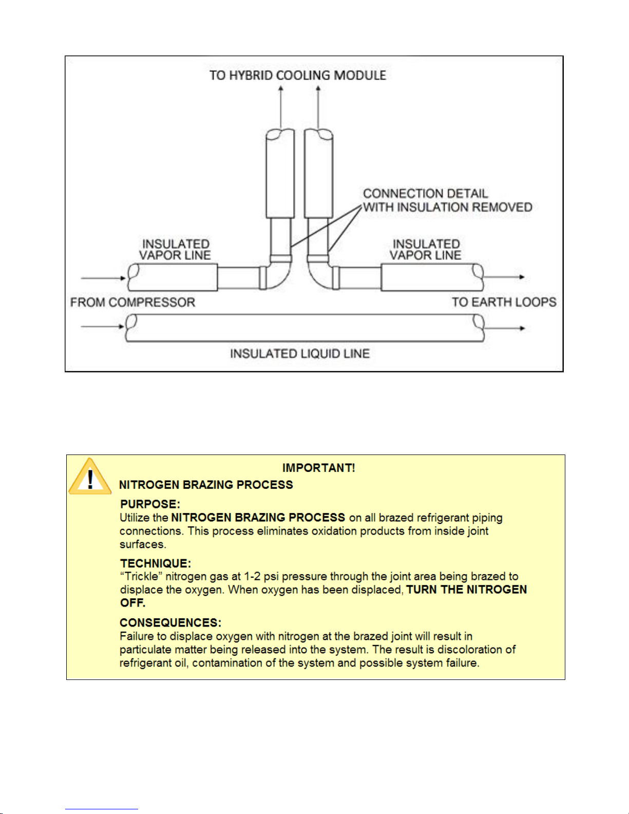
A top view of typical Hybrid Cooling Module and line set vapor line connections are illustrated in
Figure 4. For new installations of an EarthLinked system with an HCM, an alternate method to the
one shown in Figure 4 is to run a single piece vapor line from the compressor unit to the HCM and
another single piece vapor line from the HCM to the vapor manifold of the earth loop system.
IMPORTANT!
The Hybrid Cooling Module has a factory charge of dry nitrogen at
approximately 35 psig. Relieve the nitrogen from the system by means of the
Schrader valve located on the compressor unit connection shown in Figure 1.

HCM-410CP-IM (12/15) Page 8
Figure 4. Top View of Line Set Connections
All refrigerant piping joints and connections in the EarthLinked® heating and cooling system,
including the Hybrid Cooling Module, line sets and earth loop system are to be brazed with 15%
silver content brazing alloy, utilizing the NITROGEN BRAZING PROCESS.

HCM-410CP-IM (12/15) Page 9
Installation –Electrical and Start-Up
1. After turning “OFF” power to all EarthLinked®and field supplied system components at the
appropriate breakers remove the Hybrid Cooling Module control box access panel.
2. Connect appropriately sized line voltage wires and ground wire to the Hybrid Cooling
Module, as shown in Figure 5.
Figure 5. Hybrid Cooling Module Field Wiring
3. The Hybrid Cooling Module contains a pressure actuated fan speed control that has been
factory set for a pre-determined R-410A system condensing pressure.
4. Check all wiring and electrical connections to ensure proper routing and good
contact before restoring electric power, evacuating and recharging system in accordance
with the current EarthLinked®system installation manual.
WARNING!
The Hybrid Cooling Module cabinet must have an unbroken ground. The
ground must be installed in accordance with applicable electrical codes.
Failure to follow this warning can result in injury, fire or death.

HCM-410CP-IM (12/15) Page 10
Installation - Fan Speed Control
The Hybrid Cooling Module (HCM) is equipped with a variable fan speed control that varies the
speed of the fan as a direct function of the system condensing pressure. When the system is
operating in cooling mode and the compressor unit turns on, the Hybrid Cooling Module fan
speed will increase as condensing pressure increases. The fan will reach full speed at the factory-
set condensing pressure.
The system pressure setting and associated condensing temperature for full speed fan has been
factory-set and is shown in Figure 6.
Factory Setting for
Full Speed Fan
Field Adjustment Guide (per ¼ Turn)
Condensing
Pressure,
psig
Condensing
Temperature,
ºF
Setting Screw
Rotation
Condensing
Pressure
Change, psig
Condensing
Temperature
Change,
ºF
448
115
1/4 Turn
~12
~2
Figure 6. R-410A Condensing Pressure and Temperature Information
If it is necessary to adjust the full speed fan pressure setting in the field, the Hybrid Cooling Module
pressure control may be adjusted by accessing it through the HCM control panel cover.
With the control panel cover removed, the pressure control will appear as it does in the left view of
Figure 7. After removing the sealing plug, the 5/64” Allen key is inserted into the setting screw to
adjust the pressure level and associated condensing temperature for full speed fan operation.
Figure 6 indicates the change in full speed fan pressure and condensing temperature for each
¼ turn of the setting screw.
CLOCKWISE rotation of the setting screw INCREASES full speed fan pressure and condensing
temperature.
COUNTER-CLOCKWISE rotation of the setting screw REDUCES full speed fan pressure and
condensing temperature.
IMPORTANT!
Be sure that the Hybrid Cooling Module disconnect is OFF prior to removing
the control panel cover.

HCM-410CP-IM (12/15) Page 11
Figure 7. Field Adjustment Procedure
After adjustment has been made, install the sealing plug and replace and fasten the control panel
cover prior to restoring power to the Hybrid Cooling Module.
The Hybrid Cooling Module does not operate in heating mode.
This manual suits for next models
1
Table of contents
Popular Freezer manuals by other brands

Polar Electro
Polar Electro CT330 instruction manual

Miele
Miele FN 9752 i Operating and installation instructions

Zanussi
Zanussi ZFC21400WA user manual

Skope
Skope ActiveCore TMF650N Series Service manual

Whirlpool
Whirlpool EL87TRRRQ - on 35.3 Cu. Ft. SideKicks Use and care guide

saro
saro KYRA GN 700 BT instruction manual