EarthLinked PW1 User manual

PW1/PW2 KIT (09/12) Copyright 2012 Earthlinked Technologies, Inc.
EarthLinked®
Pump Wire Kits PW1 and PW2
Installation Manual
for
R-410A or R-407C Systems
Disclaimer
Proper installation and servicing of the EarthLinked®Kit is essential to the Heating and Cooling
Systems reliable performance. All EarthLinked®systems and kits must be installed and serviced by
an authorized, trained technician who has successfully completed the training class and passed the
final examination. Installation and service must be made in accordance with the instructions set
forth in this manual and the EarthLinked®Heating and Cooling System Installation, Operation and
Maintenance Manual. Failure to provide installation and service by an authorized, trained installer in
a manner consistent with these manuals will void and nullify the limited warranty coverage for the
system.
EarthLinkedTechnologies shall not be liable for any defect, unsatisfactory performance, damage or
loss, whether direct or consequential, relative to the design, manufacture, construction, application
or installation of the field specified components.
EarthLinked Technologies, Inc.
4151 South Pipkin Road
Lakeland, Florida 33811
tel. 863-701-0096 ● fax 863-701-7796
info@earthlinked.com ● www.earthlinked.com
CSI # 23 80 00

PW1/PW2 KIT (09/12) Page 2
Pre-Installation
Upon receipt of the pump wire kit, carefully check the model number against the bill of lading.
Next, check the pump wire kit model number against the compressor unit application requirement
to assure proper match of the pump wire kit to the specific application.
Pump wire kits are required for the following two types of applications. Check the application
requirements and reference Figure 1 below to ensure that you have the appropriate pump wire kit
for your specific application.
A pump wire kit is required for the following:
1) SC, SD, SCW Compressor Units in radiant panel hydronic heating applications. The specific
pump wire kit required is determined in Figure 1 from the compressor unit model and power supply.
2) SW Compressor Units utilized in an application requiring both radiant panel hydronic heating
(with an HWM) and priority domestic potable water heating (with a DWM) from a single compressor
unit. The specific pump wire kit required is determined in Figure 1 from the compressor unit model
and power supply.
POWER SUPPLY
PARAMETERS
COMPRESSOR UNIT MODEL
SC
SD
SCW
SW*
208/230-1-60
PW1
PW1
PW1
PW1
208/230-3-60
PW1
PW1
PW1
PW1
460-3-60
PW2
NA
PW2
PW1
575-3-60
PW2
NA
PW2
PW1
*SW Series available in R-407C only.
Figure 1. Pump Wire Kit Model Specification
PW1-1872 Installation
WARNING
BEFORE REMOVING ANY ACCESS PANELS AND INITIATING ANY PHASE OF
THIS INSTALLATION MAKE SURE THAT POWER IS TURNED “OFF” TO ALL
EARTHLINKED® AND FIELD SUPPLIED SYSTEM COMPONENTS. FAILURE TO DO
SO COULD RESULT IN PROPERTY DAMAGE, SERIOUS INJURY OR DEATH.
WARNING
WEAR ADEQUATE PROTECTIVE CLOTHING AND PRACTICE ALL APPLICABLE
SAFETY PRECAUTIONS WHILE INSTALLING THIS EQUIPMENT. FAILURE TO DO
SO MAY RESULT IN EQUIPMENT AND/OR PROPERTY DAMAGE, PERSONAL
INJURY OR DEATH.
1. After turning “OFF” power to all EarthLinked® and field supplied system components at the
appropriate breakers, remove the front and top panels of the compressor unit cabinet.
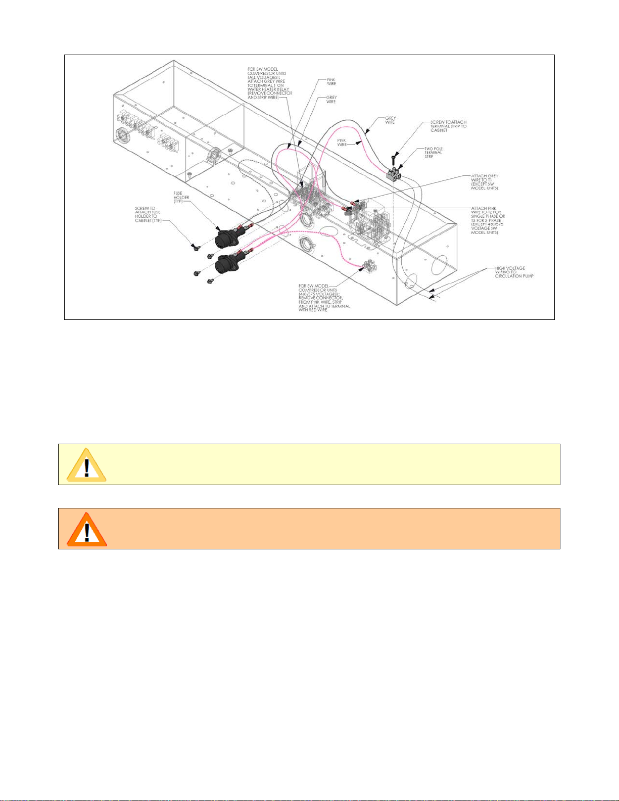
2. Reference Figure 2 for PW1 assembly to electrical box. Remove available hole covers from the
front of the electrical box.

PW1/PW2 KIT (09/12) Page 3
Figure 2. PW1 Assembly to Electrical Box
3. Install fuse holders into existing fuse holes with screws provided. Install fuses in fuse holders.
4. Install two-pole terminal strip inside electrical box and fasten into existing hole with screw
provided.
5. Attach pink wire with piggyback connector onto “T2” (for single phase) or “T3” (for 230 volt,
three phase) on the compressor contactor and the other connector to the center terminal of the
bottom fuse holder.
IMPORTANT
USE PIGGY BACK TO REATTACH WIRES IF NO TABS ARE AVAILABLE FOR
INSTALLING KIT.
CAUTION
DO NOT REMOVE CLIP BY PULLING ON WIRE.
DO NOT ALLOW PIGGY BACK CLIP TO TOUCH OTHER TERMINALS.
6. For SC, SD and SCW compressor unit models, attach the gray wire with the piggy back
connector onto “T1” on the compressor contactor, and the other connector to the center terminal
of the top fuse holder.
7. For SW compressor unit models for application to radiant panel hydronic heating and priority
domestic potable water heating, install the piggy back onto terminal “5” of the heat-cool relay.
8. Attach the pink wire with connector to the collar connection of the bottom fuse holder, and
tighten the terminal screw of the terminal block onto the stripped end of the pink wire.
9. Attach the gray wire with connector to the collar of the top fuse holder, and tighten the other
terminal screw of the terminal block onto the stripped end of the gray wire.
10. Run high voltage wiring from the two-pole terminal strip in the electrical box out the grommeted
end hole of the electrical box and through the conduit connection of the compressor cabinet, to
the circulating pump motor.

PW1/PW2 KIT (09/12) Page 4
11. Check all wiring and connections to ensure proper routing and good contact to connections
before restoring power to all the system components.
PW2-1872 Installation
WARNING
BEFORE REMOVING ANY ACCESS PANELS AND INITIATING ANY PHASE OF
THIS INSTALLATION MAKE SURE THAT POWER IS TURNED “OFF” TO ALL
EARTHLINKED® AND FIELD SUPPLIED SYSTEM COMPONENTS. FAILURE TO DO
SO COULD RESULT IN PROPERTY DAMAGE, SERIOUS INJURY OR DEATH.
WARNING
WEAR ADEQUATE PROTECTIVE CLOTHING AND PRACTICE ALL APPLICABLE
SAFETY PRECAUTIONS WHILE INSTALLING THIS EQUIPMENT. FAILURE TO DO
SO MAY RESULT IN EQUIPMENT AND/OR PROPERTY DAMAGE, PERSONAL
INJURY OR DEATH.
IMPORTANT
THE PW2 PUMP WIRE KIT IS INSTALLED ON SC, SD AND SCW MODEL
COMPRESSOR UNITS ONLY.
THE SW MODEL COMPRESSOR UNITS TAKE THE PW1 PUMP WIRE KIT.
1. After turning “OFF” power to all EarthLinked® and field supplied system components at the
appropriate breakers, remove the front and top panels of the compressor unit cabinet.
2. Reference Figure 3 for PW2 assembly to electrical box. Remove available hole covers from the
front of the electrical box.

PW1/PW2 KIT (09/12) Page 5
Figure 3. PW2 Assembly to Electrical Box and Base Pan
3. Install fuse holders into existing fuse holes with screws provided. Install fuses in fuse holders.
4. Install the two-pole terminal strip inside electrical box and fasten into the existing hole with
screw provided.
5. Reference Figure 3 for the location of the transformer for the SC and SD Model compressor
units, and a different location for the SCW model compressor unit.
6. Using the transformer base as a template, drill four holes in the base pan to accommodate #10-
6 screws provided. Collect and dispose of all metal shavings from drilled holes.
7. Fasten the transformer firmly to the base pan with the screws provided.
8. Route the stripped pink and gray wires form the transformer through the grommeted bottom
center hole of the electrical box and attach to the terminal strip terminals by tightening the
terminal screws onto the stripped wire ends.
9. Route the pink and gray wires with connectors and the green stripped-end wire from the
transformer through the grommeted bottom center hole of the electrical box and connect as
follows:
a. Pink wire to the collar connection of the BOTTOM fuse holder.
b. Gray wire to the collar connection of the TOP fuse holder.
c. Green wire with stripped end to the #6 high voltage terminal strip.

PW1/PW2 KIT (09/12) Page 6
10. Install the pink wire with the piggy back connector onto the compressor contactor terminal “T3”
for 460/575 volt three phase, and the connector at the other end of the same wire to the center
terminal of the BOTTOM fuse holder.
11. Install the gray wire with the piggy back connector onto the compressor contactor terminal “T1”
and the connector at the other end of the same wire to the center terminal of the TOP fuse
holder.
12. Run high voltage wiring from the two-pole terminal strip in the electrical box out the grommeted
end hole of the electrical box through the conduit connection of the compressor cabinet to the
circulating pump motor.
13. Check all wiring and connections to ensure proper routing and good contact at connections,
before restoring power to all the system components.
This manual suits for next models
1
Table of contents
Popular Water Pump manuals by other brands

True Source
True Source TS-60 Series user manual

AMT
AMT 4430-95 Information manual

Jesco
Jesco MEMDOS E Operation manual

PRAKASH
PRAKASH SP-R5A-8 Installation, maintenance and operation manual

Becker
Becker VT 4.2 operating instructions

GORMAN-RUPP PUMPS
GORMAN-RUPP PUMPS SFV4C Installation, operation, and maintenance manual with parts list

Buffalo Tools
Buffalo Tools TWPUMP Assembly & operating instructions

Wilo
Wilo Rexa UNI Installation and operating instructions

Giant
Giant LP122A Series Operating and service manual

Oilpress Keller
Oilpress Keller 286.932 operating instructions

SKF
SKF LAGG 18M Instructions for use

Ribiland
Ribiland PRSI24JET101I User and maintenance manual