Easycar E8-B User manual

INSTALLATION GUIDE
U S A
EP400 / E8-B
www.Easycar-USA.com
www.Easycar-USA.com


4
INSTALLATION GUIDE
5
INSTALLATION GUIDE
USA USA
1. Wire Connection Guides
➢Heavy Gauge, 10-pin Connector (CN1)
There are 6 heavy gauge wires coming from the large 6-pin connector. They are
used to energize the ignition circuits in the vehicle. It is crucial to ensure that these
connections are capable of handling the current demands. For this reason, Scotch-
Locks, T-taps and other such connectors are strongly discouraged.
CN1/1 YELLOW STARTER OUTPUT
After cutting the starter wire, connect the YELLOW wire to the ignition switch wire.
This wire supplies power to the starter motor output.
CN1/2 WHITE (+) IGNITION 2
This wire is the polarity feed for the ignition 2. (+) 12V with the key ON and 0V in
the START position. This wire supplies power to subsidiary accessories such as car
audio, lights and to climate control such as air conditioner and heater. If the vehicle
is not equipped with this wire, do not connect it.
CN1/3 GREEN (+) IGNITION 1 INPUT/OUTPUT
Search for a 0 volt wire with the key in the ACC position, (+) 12V wire with the key on
the ON position, and (+) 12V wire with the key on the START position.
CN1/4 RED/WHITE (+) MAIN POWER 2
Connect to constant (+) 12V source, minimum 30A capacity.
CN1/5 BLUE (+) ACC
Search for a wire that is 0V with the key in the OFF position, (+) 12V with the key on
the ACC & ON position, and 0V with the key on the START position.
CN1/6 RED (+) MAIN POWER 1
Connect to constant (+) 12V source, minimum 30A capacity.
Before Beginning the Installation
• Please read this entire installation guide before beginning the installation.
The installation of this push button remote start system requires interfacing with
many of the vehicle’s systems. Many new vehicles use low-voltage or multiplexed
systems that can be damaged by low resistance testing devices, such as test lights
and logic probes (computer safe test lights). Test all circuits with a high quality digital
multi-meter before making connections.
• Do not disconnect the battery if the vehicle has an anti-theft-coded radio.
If equipped with an air bag, avoid disconnecting the battery if possible. Many airbag
systems display a diagnostic code through their warning lights after they lose power.
Disconnecting the battery requires this code to be erased, which can require a trip to
the dealer.
• Roll down a window to avoid being locked out of the car.

6
INSTALLATION GUIDE
7
INSTALLATION GUIDE
USA USA
➢Door Lock Harness, 6-pin Connector (CN2)
CN2/1 BLACK (-) GROUND
CN2/ 6 PIN PLUG
AFTER MARKET DOOR LOCK SYSTEM
CN2/ 3 PIN PLUG
OEM DOOR LOCK SYSTEM
➢Primary Harness (CN3)
CN3/1 YELLOW DOOR UNLOCK OUTPUT
CN3/2 GREEN DOOR LOCK OUTPUT
N
egative Door Lock System
Positive Door Lock System
Reverse Polarity System
Vacuum Door Lock System
Installation Essentiality Matters
Door Connection (CN2)
For the Vehicle
with OEM
Power Door Lock System
For the Vehicle
with After Market
Power Door Lock System

8
INSTALLATION GUIDE
9
INSTALLATION GUIDE
USA USA
Negative One-Way System
Positive One-Way System
CN3/3 VIOLET (+) PARKING LIGHT OUTPUT
This wire should be connected to the parking light (+) wire in the vehicle.
CN3/4 GRAY (+) KEY TRIGGER OUTPUT
For vehicles with an auto escort light, please proceed with the following.
1) With the key out from the key box, find the (+) 12V wire and cut the wire.
2) Directly connect the (+) side of the cut wire to the CN3/4 wire.
CN3/5 BROWN (+) TRUNK RELEASE OUTPUT
When the system receives the code controlling trunk release output for longer than
1.5 seconds, the BROWN wire supplies an output as long as the transmission
continues. This is typically used to operate a trunk/hatch release or other relay-driven
function.
CN3/6 WHITE (+) SIREN OUTPUT
Connect this to the BROWN (+) wire of the siren.
CN3/7 ORANGE (-250mA) KEY TRIGGER OUTPUT
For vehicles with an auto escort light, please proceed with the following.
1) With the key out from the key box, find the (+) 12V wire and cut the wire.
2) Directly connect the (-) side of the cut wire to the CN3/7 wire.
CN3/8 BLUE (-) PARKING LIGHT OUTPUT
This wire should be connected to the parking light (-) wire in the vehicle.
CN3/9 VIOLET/WHITE
(-250mA) STATUS/BYPASS
CN3/10 BLACK
(-) GROUND

10
INSTALLATION GUIDE
11
INSTALLATION GUIDE
USA USA
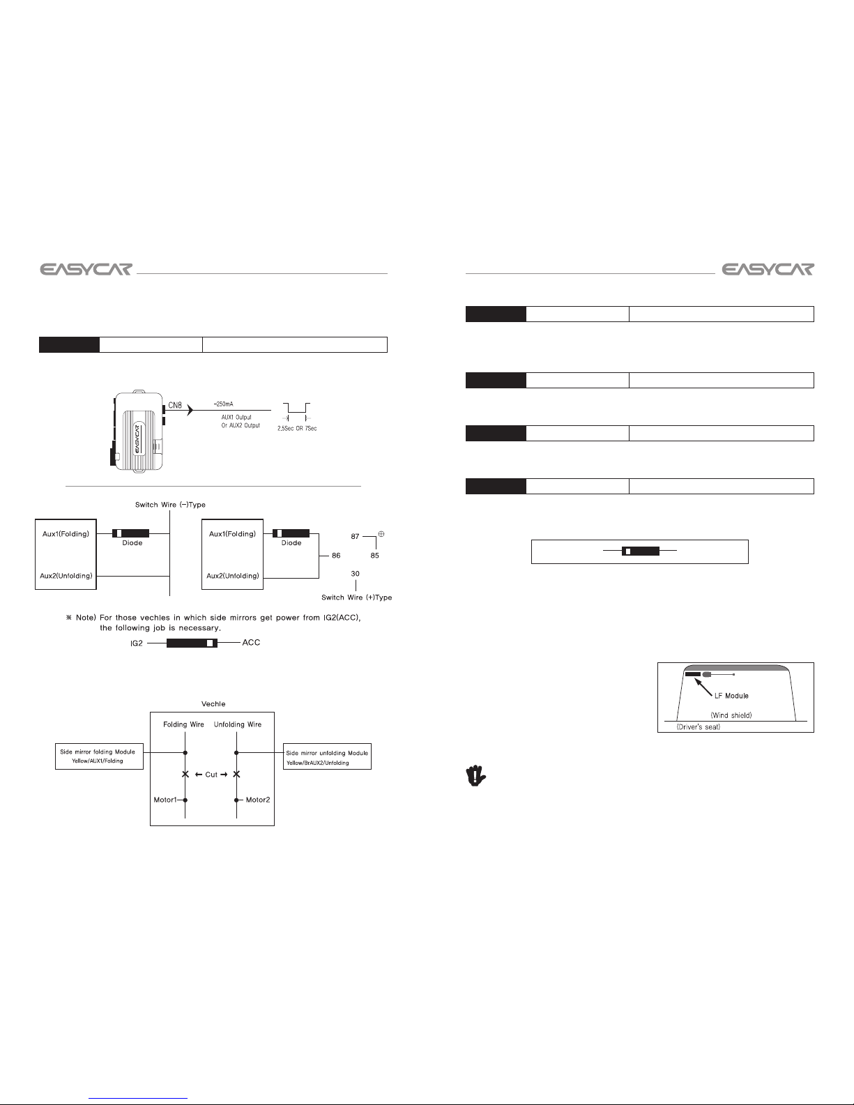
➢Additional Harness (CN4)
CN4/1 GREEN (+) TACHOMETER INPUT WIRE
This input provides the module with information about the engine’s revolutions per
minute (RPMs). It can be connected to the uncommon colored wire of the fuel
injector, the crankshaft position sensor, the camshaft position sensor or the negative
side of the coil in vehicles with conventional coils. In multi-coil and high energy
ignition systems locating a proper signal may be more difficult. It will shows lower
than 5V without engine running (with the key ON) , 7V-14V with engine running.
(This wire can be utilized as a tach sensing wire. Please confirm the dip switch on
the main unit is in correct position.)
CN4/2 BROWN (+) PARKING LIGHT INPUT
Connect this wire to parking light (+). This wire is connected to prevent the vehicle
from discharging. When the parking light or headlight is ON during the arming
stage, it sends warning signal to the transmitter. (Pager model ONLY)
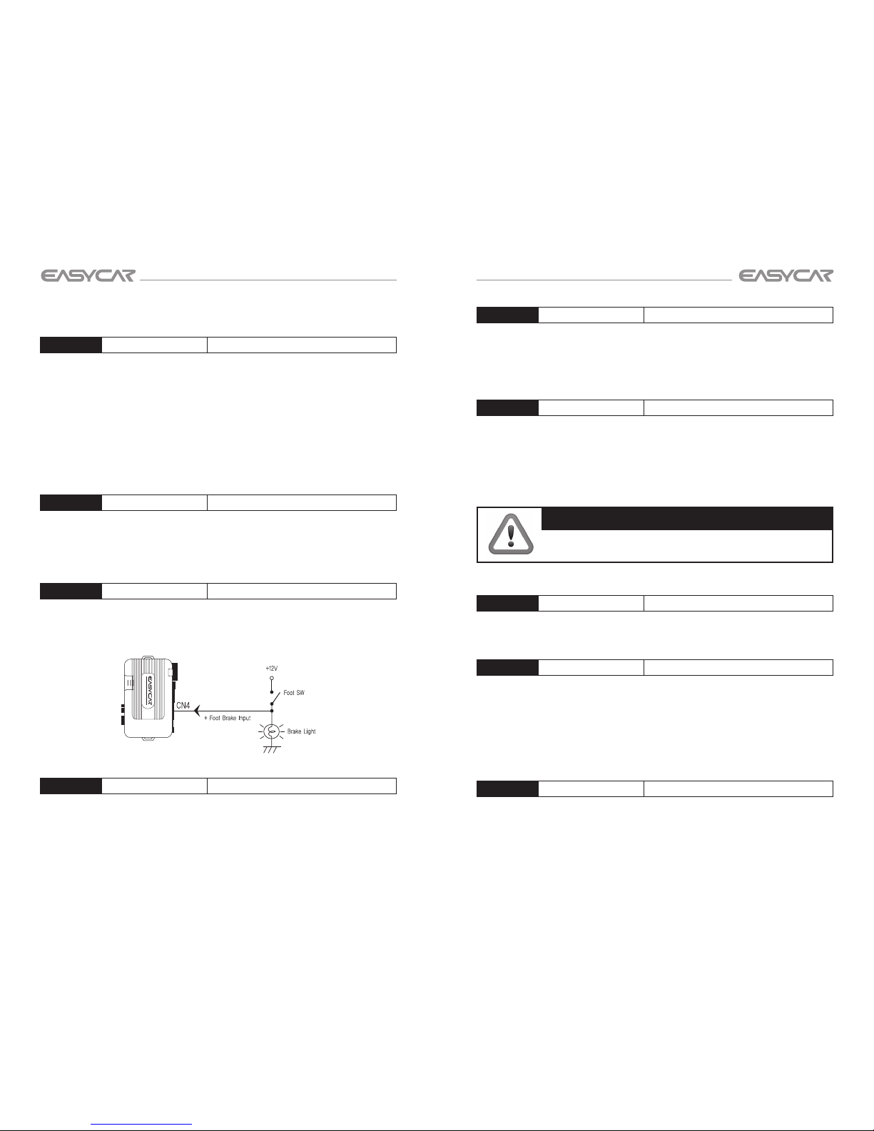
CN4/3 YELLOW (+) FOOT BRAKE (BRAKE SHUTDOWN WIRE)
This wire MUST be connected to the vehicle’s brake light wire. This is the wire that
shows (+) 12V when the brake pedal is depressed. The remote start is disabled or
shuts down any time the brake pedal is depressed.
CN4/4 RED (+) DOOR TRIGGER
This wire is used in vehicles that have a positive (+) switched dome light circuit.
Connect the RED wire to a wire that shows (+) 12V when any door is opened, and
ground when the door is closed.
CN4/5 RED/BLACK (-) DOOR TRIGGER
Most vehicles use negative door trigger circuits. Connect the RED/BLACK wire to a
wire that shows ground when any door is opened. In vehicles with factory delays on
the dome light circuit, there is usually a wire that is unaffected by the delay circuitry.
CN4/6 WHITE (-) PARKING BRAKE/NEUTRAL SAFETY INPUT
(Automatic transmission) Connect this wire to a ground source when the gear is in
the Parking position or Emergency brake is applied.
(Manual transmission) Connect this wire to a ground source when the Emergency
brake is applied. This input MUST rest at ground in order for the remote start system
to operate.
IMPORTANT!
Always verify that the vehicle cannot be started in ANY drive
gear and that the override switch is functioning properly.
CN4/7 BLUE (+) SYSTEM TURN ON
Connect this wire to the (+) 12V. This is Push Button Start key signal wire.
CN4/8 ORANGE/BLACK (-) DIESEL WAIT TO START INPUT
Connect this wire to the wire in the vehicle that sends the signal to turn on the Wait-
To-Start bulb in the dashboard. In most diesels the wire is negative (ground turns
on the bulb) and the ORANGE/BLACK wire can be directly connected to the wire in
the vehicle. If the vehicle uses a positive wire (12V to turn on the bulb) a relay must
be used to change the polarity.
CN4/9 VIOLET/BLACK (-) TRUNK TRIGGER INPUT
This input responds with an instant (-) trunk trigger.

12
INSTALLATION GUIDE
13
INSTALLATION GUIDE
USA USA
➢Easy Door Lock Sensor, LED Light Connector (CN5)
Easy Door Lock Sensor
Doors can be locked (armed) or unlocked (disarmed) without the remote or car keys
with this function. Simply input the 4 digit pass-code by knocking on the Easy Door
Lock Sensor on the front windshield.
** On the pager model (E8-B), knocking twice on the sensor will send a call signal to
the pager remote. However, it will not operate when the vehicle is on the ON position
nor when the engine is running.
LED Light
The 10 digit blue LED displays various functions such as arming, disarming, valet
mode and emergency status (panic, shock, and theft).
➢ Dual Shock Sensor (CN6)
Install the sensor in a central loca-
tion and adjust its sensitivity after
opening the door in accordance
with different shocks and status of
LEDs on the shock sensor. It sens-
es shocks by two steps (strong and
weak shock).
➢Antenna Module (CN7)
Mount the antenna horizontally at the top left or right corner of the front windshield.
The transmitting distance may decrease if the vehicle has a UV protective coating
on the windshield.
➢Start Button (CN8)
1. Push button ON/OFF
<Ignition Off>
<Ignition On>
1-1) Engine ON
To start your vehicle, press the
brake and press the Push-to-Start
button. The “STOP” will illuminate
to red.
Once the parking brake
(automatic transmission) or the
emergency brake (manual
transmission) is released, the
red illumination will disappear. Once the red "STOP" illumination disappears,
you will not be able to stop the engine.
1-2) Engine OFF
To turn your engine off, press the brake and press the Push-to-Start button.
Once the parking brake (automatic transmission) or the emergency brake
(manual transmission) is engaged, the green illumination will appear on
“START”.
2. OFF ACC ON OFF
<ON>
<ACC>
2-1) ACC
To enable the vehicle in the ACC mode,
press the Push-to-Start button once
without pressing on the brake
2-2) ON
To enable the vehicle in the Ignition ON
mode, press the Push-to-Start button
twice without pressing on the brake.

14
INSTALLATION GUIDE
15
INSTALLATION GUIDE
USA USA
➢Auxiliary Harness (CN9)
CN9/1 YELLOW (-250mA) AUX 1 OUTPUT
This wire provides (-) 250mA programmable output whenever the transmitter
button(s) controlling Aux 1 is pressed.
• For two switch vehicles: Please connect it with folding Switch wire as below
CN9/2 YELLOW/BLACK (-250mA) AUX 2 OUTPUT
This wire provides (-) 250mA programmable output whenever the transmitter
button(s) controlling Aux 2 is pressed.
CN9/3 VIOLET (-250mA) STARTER KILL
This wire supplies a (-) 250mA ground as long as the system is armed.
CN9/4 BLANK N/A
CN9/5 GREY/BLACK (-250mA) AUTO LIGHT CONTROL OUTPUT
Utilize this option to stop the auto light function in remote start, reservation start,
and turbo start modes.
Autolight control
(gray/black)
Door trigger pin in
driver seat
➢LF Module - Smart Door (CN10)
Mount the LF module on the front windshield (if the LF module is mounted under
the dash, it decreases the transmitting
distance). When the Smart Remote is
within the communication range (6 - 8 feet)
of the LF module, it will unlock the vehicle.
When the Smart Remote is not detected in
the communication range (6 - 8 feet),
the vehicle will lock within 12~15 seconds.
Note
The Smart Door function mode can be activated from the remote. Simply hold the
unlock button for 3 seconds to activate the Smart Door mode.

16
INSTALLATION GUIDE
17
INSTALLATION GUIDE
USA USA
➢Temperature Sensor (CN11): E8-B ONLY
This sensor senses the interior temperature of the vehicle. Do not mount the
sensor on the floor or the body of the vehicle.
2. Selection For Automatic and Manual
Transmission
The Jumper wire inside the cover of the main unit is used for Manual transmission
vehicles. If the unit is installed on an Automatic transmission vehicle, simply cut
the Jumper wire.
WARNING!
Do not reconnect the Jumper wire once it has been cut. It will
void all warranty and it is very unsafe.
3. Alternator Sensor
1. Dip Switch
2. Noise Sensing LED
Noisy Sensing LED
LED
The LED on the cover of the main controller unit is lit when the engine is running
and the light is turned off when the engine is off.
4. Programming
IMPORTANT!
These steps must be completed in order for the
product to operate properly.
A. Remote Control Registration
1) Press the “Start” button (OFF ACC ON) 4 times; “ON” light should be
displayed. (Parking light flash once, ready to program the remotes)
2) Press the I or button on the 1st remote.
3) Then press the I or button on the 2nd remote.
(When the lock button is pressed on the remote, paking light flash once)
4) Remote programming is now complete.

18
INSTALLATION GUIDE
19
INSTALLATION GUIDE
USA USA
C. Smart Door Lock Registration
1) Open the driver side door.
2) Make sure the Push-to-Start button is set to the “OFF” position.
(“START” light should be lit)
3) Press the II or button for 2 seconds on the 1st remote.
(Siren will beep twice)
4) Press the II or button for 2 seconds on the 2nd remote.
(Siren will beep twice)
5) Smart Door programming is now complete.
5. Remote/Push Button Start Diagnostics
When the remote start function is activated and the vehicle emits an error tone
(3 chirps); you have the ability to see what the cause of the no-start situation is by
counting the amount of flashes of the parking lights from the vehicle.
Number of parking
lights flashes Cause of Error
1 Engine is on
2 Ignition is to the ON position
3Door is open (Door wire is active) or Knock Sensor is not
programmed
4 Trunk is open (Trunk wire is active)
5 Brake is being pressed (Brake wire is active)
6 CN4/7 wire is not connected
7 Manual transmission mode is enabled and not initialized
8
Parking brake / Emergency brake is off
Neutral safety wire has no ground or the neutral safety switch
is off
B. Easy Door Lock Program
(Push button will not operate until Easy Door Lock is programmed)
1) Decide on a passcode, a 4 digit number. (i.e. 1234)
2) Step into the vehicle.
3) Open the driver side door.
4) Press the “Start” button so that it is on the “Ignition ON” position.
5) Step out of the vehicle.
6) Knock on the Easy Door Lock a few times until you see all the LED lights flash.
7) LED light will now move from 1 to 0.
(Each number will be lit for 2 seconds)
8) Knock on the pad when the number to your passcode is lit.
(Each time a number is entered, the LED light will restart from the 1 position)
i.e.) On a passcode for 1234.
a.Tap when the LED light is lit on the 1.
b.LED light will restart from the 1 position and move onto 2.
c. Tap when the LED light is lit on the 2.
d. LED light will restart from the 1 position and move onto 2 and 3.
e.Tap when the LED light is lit on the 3.
f. LED light will restart from the 1 position and move onto 2, 3 and 4.
g.Tap when the LED light is lit on the 4.
9) Once all 4 number passcodes are entered, the siren will beep once and the
parking light will flash once.
10) Easy Door Lock programming is now complete.

20
INSTALLATION GUIDE
21
INSTALLATION GUIDE
USA USA
6. How to Program the Options
A. To Program
1) Review the options above and remember the button sequence required for
that specific option.
2) Press the I + IV ( + ) button simultaneously for 2 seconds to begin the
programming mode. The vehicle’s parking lights will flash once and chirp
once, stating that it is now in programming mode.
3) Immediately press the two corresponding buttons (one after another).
i.e.) Sound Select option press I ( ), then IV ( ).
4) Within 3 seconds, the vehicle’s parking lights will flash as well as chirp;
corresponding to the first button pressed followed by chirp(s) and flashes
matching the second button pressed.
i.e.) Sound Select option vehicle chirps once with one flash (since the I ( )
button was pressed), followed by 4 chirps and 4 flashes (since the IV button
was pressed).
5) To end programming mode, press I + IV ( + ) for 2 seconds. It will also
end programming with 30 seconds of inactivity. The vehicle’s parking lights will
flash once and chirp once, stating that it is now out of the programming mode.
B. Incorrect Programming
Vehicle will chirp once to warn you that the programming was not properly
programmed.
Please begin the programming once again.
C. Factory Setting Reset
1) Press the I + IV ( + ) button simultaneously for 2 seconds to begin the
programming mode. The vehicle’s parking lights will flash once and chirp once,
stating that it is now in programming mode.
2) Immediately press IV ( ) twice. Within 3 seconds, the vehicle’s parking lights
will flash as well as chirp four times, followed by four chirps and flashes.
3) To end programming mode, press I + IV ( + ) for 2 seconds. It will also end
programming with 30 seconds of inactivity. The vehicle’s parking lights will flash
once and chirp once, stating that it is now out of the programming mode.
Tech Support available on Monday thru Saturday, 9am ~ 5pm (PST)
(562) 841-4968

M/E/M/O
U S A
Select Market Trading, Inc.
Limited One Year Warranty
This limited warranty is given to the end-user or the retail purchaser (referred to this warranty as "Original Purchaser")
that it will be free from defects in material and workmanship for a period of 1 year from the date of the purchase of
the new product (excluding accessory items such as harness, keypad, antenna, remote control and pager). A copy
of the original proof of purchase and this warranty card with RMA number given by Select Market Trading,
Inc. is required to receive warranty service. In the unlikely event that the new product should fail due to defect in
material or workmanship, Select Market Trading, Inc. will repair or replace the entire product, where each party will
be responsible for one-way shipping.
This limited warranty does not cover any physical damage to this product, damage caused by improper installation;
improper use; misuse; neglect; repair of cracked, scratched, broken or modified cosmetics; or parts that have been
altered or removed; damages done by another device used with this product resulting from use of non Easycar USATM
- brand parts. This warranty is VOID if you purchased this product as used, floor model sample, or refurbished; if the
product has been altered or modified in any way (including but not limited to attempted repair without authorization
from Easycar USATM - Select Market Trading, Inc. and/or alteration/removal of the serial number). This limited
warranty does not cover the vehicle of any damages or liabilities in which this product is installed or being installed.
This product does not guarantee avoidance of vehicle collision or accident.
If you think your product is eligible for warranty service, please email to [email protected] to receive an RMA
Number with further instructions.
Model Number:
Serial Number:
Date of Purchase:
Purchased Store Name:
RMA Number:
Reason:
Name:
Address:
City:
State:
Zip:
Tel:
Important: An RMA (Return Material Authorization) is REQUIRED to receive warranty on defective
products, along with proof of purchase and this warranty card.

This manual suits for next models
1
Table of contents
Other Easycar Car Alarm manuals