Easystreet 75532 User manual

1
Technical Support
1-800-248-0892
1992-2001HondaPrelude
FrontKitPartNo.75532
www.airliftcompany.com
MN-542
(04409)
NPR 4778
Pleasereadtheseinstructionscompletelybeforeproceedingwithinstallation
EASYSTREET
Warranty Information
1. All goods come with a one year manufacturer’s warranty against defects.
2. Warranty will be void if the strut is altered for any reason and/or adapted to
applicationsotherthanthosesuggested.
3. Any abrasions or rub marks on the spring portion of the strut will not be covered
under warranty. The customer is responsible for all repair charges.
4. Driving at a low PSI can cause thestruttobottomout. Repeatedbottomingoutcan
causethe strut to fail. Failure resulting from repeated bottoming out is notcovered
under warranty.
5. The customer is responsible for all shipping costs to Air Lift Company for all warranty
claims.
6. Please calltechsupportat1-800-248-0892beforeshippingaproducttoAir Lift
Company.

2
Technical Support
1-800-248-0892
Figure 1 IMPORTANT: Alwayskeepsafetyinmindwhenworking
on your vehicle. Completely read these instructions
before installing the kit.
I. PreparingtheVehicle
1. Begintheinstallation by elevatingthe car. Secure theframe with
jack stands.
2. Removethefront wheels.
II.StrutRemoval
1. Remove the three nuts on the top of the strut and retain for later
use. Theseare locatedonthe insideof theenginecompartment
above the strut pocket (Figure 1).
2. Remove the anti-rotation bolt that holds the lower strut to the
fork and retain for later use.
3. Move the fork out of the way.
4. Remove the strut assembly and upper strut mount from the
vehicle.
NOTE: The upper strut mount and the anti-rotation bolt will be
used for reassembly.
Figure 2
Figure 3
Hardware
Item P/N Description Qty.
35066 StrutAssembly 2
09333 RubberWasher 2
C 21263 1/4”NPT x 1/2”Tube Elbow 2
A
B

3
Technical Support
1-800-248-0892
III.AssemblingtheStrut
1. Remove the O.E.M.rubber bumper from the O.E.M.upper strut
mount(Figure2).
2. Marka notchon asideoftheupperstrutmount usingthe grooves
in the top of the strut mount as a guide (Figure 3).
3. Cutouta notchlarge enoughtoclear theair fittingwhenthestrut
is in place (Figure 4).
NOTE: Steps four through seven are shown in Figure 5.
4. Insert the supplied 1/2” 90° air fitting (C) into the strut.
5. Place a supplied rubber washer (B) onto the bolt at the top of the
strut.
6. Place the previoulsy removed O.E.M. rubber bumper on top of
thewasher.
7. Put the upper strut mount back in place on top of the rubber
bumper and fasten using a supplied flat washer and nylock nut.
8. Tighten only finger-tight at this time.
9. Tighten the fitting finger-tight plus 1 1/2 turns being careful to
tighten on the metal hex nut only.
NOTE: The fitting needs to be turned so that a base of the hex
nut is parallel to the end cap (Figure 6).
V. SpindleCastingFlash
IMPORTANT: This stepiscriticaltothe lifeand
performanceofyourairbags.
1. It will be necessary to grind the inside of the flashing off the
spindle arm that attaches to the upper control arm (Figure7).
Caution: Failure to grind the flashing may cause the air bag
to rub against the spindle arm flashing and rupture. This
will void the air bag warranty.
NOTE: Make sure the face is smooth and clear of burrs.
Figure 5
Figure 6
Figure 4
Correct Air
Fitting Installation:
Hex Nut edges are
parallel with top
and bottom upper
end cap edges.
Incorrect Air
Fitting Installation:
Hex Nut point extends
over bottom of upper
end cap edge and
could puncture air bag.
Grind OffGrind Off
Flashing fromFlashing from
SpindleSpindle
Grind Off
Flashing from
Spindle
Figure 7

4
Technical Support
1-800-248-0892
Trim
Trim
Flange
Flange
Trim
Flange
VI. TrimmingtheUpperA-Arm
NOTE: It will be necessary to trim the flange off of
theupperA-arm inordertomakeclearanceforthe
flexmember (Figure8).
1. Removethecontrolarmmountinghardwareandreplacewithbolts
(D), flatwashers (E), and nylock nuts (C) being sure to insert them
withtheboltheadsfacingtheinsideofthecontrolmountinorderto
provideadequateclearancefortheairstrut(Figure8).
2. The inside flange on the upper control arm can be trimmed by
usingadie grinderwith acut-offwheelorgrinding bit.Be sureall
sharp edges are removed, and paint the exposed area when
complete(Figure8).
3. Thetop barfortheuppercontrolarmwill alsoneedtobetrimmed.
Grind1/8”off of a3” area (Figure8).
IV.Installing the StrutAssembly
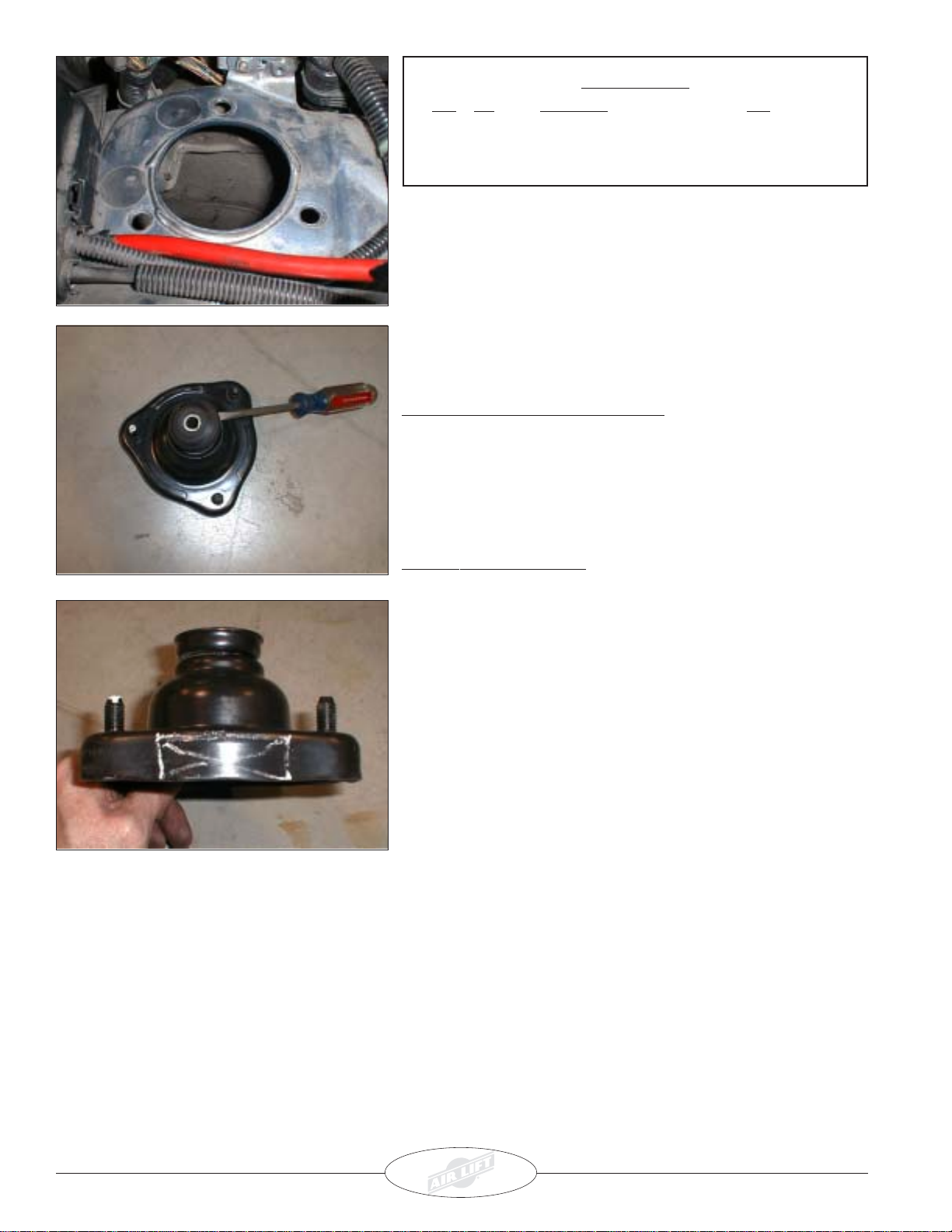
1. Using the template at the end of the manual, line up the three
holesin thetemplate withthe threeholes inthe upperstrut tower.
2. Make a mark in the engine compartment where the fourth hole
will need to be drilled.
3. Remove the template and drill a hole in the upper strut tower
large enough to accomodate the air fitting from the top of the
strut(Figure9).
NOTE: Be surethat youhaveadequate clearancebeforedrilling.
NOTE: The same template will be used for both sides of the
vehicle.
NOTE: A silicone seal or rubber grommett is recommended to
protect the air line where it passes through the strut tower.
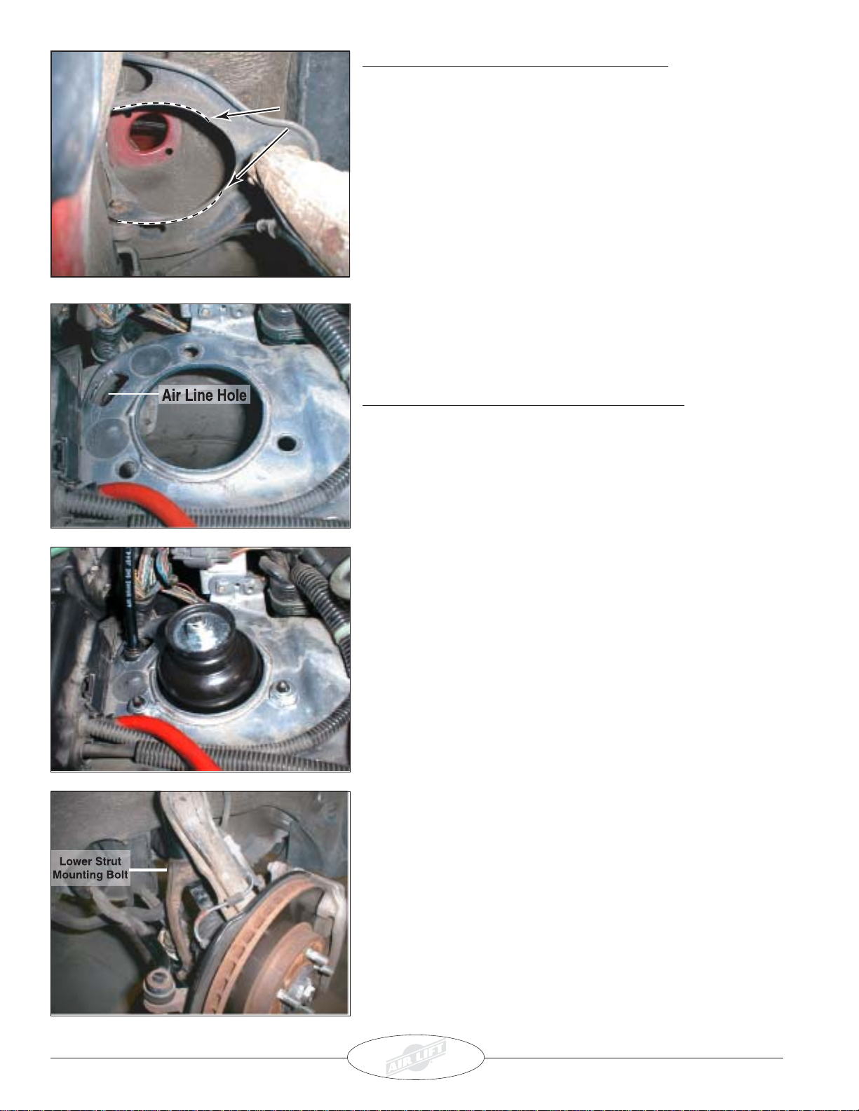
4. Place the upper strut mount back into the compartment.
NOTE: Rotate thestrutassembly sothatthe air fittingisthrough
the center previously drilled hole.
5. Fastenthestrut usingthethree previouslyremovednuts(Figure 10).
6. Tighten the nut at the top of the upper strut mount at this time.
7. Slide the lower end of the strut into the strut fork.
8. Replacethe previouslyremovedlowerstrutmountingbolt(Figure
11). Leave loose at this time.
9. Tighten the the lower strut mounting bolt.
10.Securelytighten thethreenylocknutsintheenginecompartment.
11. Install the air line at this time (Figure 10).
Figure 11
Figure 10
Figure 9
Figure 8

5
Technical Support
1-800-248-0892
V. Before Operating
1. Inflate and deflate system (do not exceed 150 p.s.i) to check for clearance or binding issues. With air springs
deflated, check clearances on everything so as not to pinch brake lines, vent tubes, etc. Clear lines if necessary.
2. Tighten and visually inspect all hardware after 100 miles.
3. The struts for the vehicle come with a nine-position dampening dial (shown below) for added adjustability. To start,
we recommend setting the dial at the third position for the most versatility.
4. Air Lift part #27741 is highly recommended for this product.
5. Pleasecontinueby readingtheMaintenance and Operationsection.
9-position
dampening
dial
strut body
VI. MaintenanceandOperation:
By following these steps, vehicle owners should obtain the longest life and best results from their air springs.
1. Always maintain Ride Height. Never inflate beyond 150 p.s.i.
2. Alwaysadjust theair pressureto maintainRide Height. Increaseor decreasepressure fromthe systemas necessary
to attain Ride Height for optimal ride and handling.
3. Should it become necessary to raise the vehicle by the frame or do any service work, make sure the system is at
minimum pressure (10 p.s.i.) for safety and to reduce the tension on the suspension/brake components.
MinimumPressure Maximum Pressure
10p.s.i. 150 p.s.i.
Failureto maintaincorrect minimumpressure(or pressure proportionalto load),bottoming
out,overextension,or rubbingagainst anothercomponent willvoidthewarranty.

6
Technical Support
1-800-248-0892
10
EASYSTREET
10
“The Choice of the Professional Installer”
For Technical Assistance call 1-800-248-0892
Thank you for purchasing Air Lift Products
Mailing Address: Street Address:
AIR LIFT COMPANY AIR LIFT COMPANY
P.O.Box 80167 2727 Snow Rd.
Lansing, MI 48908-0167 Lansing, MI 48917
Local Phone: (517) 322-2144
Fax: (517) 322-0240
Printed in the USA
Trim the Outer Edge of theTemplate as Necessary
Flip the template over for the remaining side of the vehicle.
Table of contents
Popular Motorized Toy Car manuals by other brands

Kogan
Kogan KAMERSUVBKA user guide

Fisher-Price
Fisher-Price Power Wheels V4343 Owner's manual with assembly instructions

Carrera RC
Carrera RC Mario Kart 8 Mario Assembly and operating instructions

Reely
Reely Slim Dart operating instructions

Team Losi
Team Losi LOSB0221 Getting started

Canon
Canon Creative Park Mercedes Benz 500K Assembly instructions