manuals.online logo
Brands
  1. Home
  2. •
  3. Brands
  4. •
  5. EAW
  6. •
  7. Universal Remote
  8. •
  9. EAW UR1 User manual

EAW UR1 User manual

The UR1 is a real-time universal remote
control. The UR1 may be programmed to operate
any number of things, such as volume, muting
inputs, recalling priorities, etc. Up to ten UR-family
remotes may be connected to one DX Remote bus
port on the rear of a DX family processor
(e.g. DX1208).
The function of each DX Remote is software
programmable from within the DX Navigator
software application.
Quick-Start Guide
SAFETY FIRST!
Before connecting and using the equipment,
please read this Quick-Start Guide carefully
and keep it for future reference.
WARNING! This equipment has been
designed to be installed by qualified
professionals only! There are many factors to
be considered when installing professional
sound reinforcement systems. Some of these
factors include mechanical and electrical
considerations, as well as acoustic coverage
and performance. LOUD Technologies strongly
recommends that this equipment be installed
only by a professional sound installer or
contractor.
1. Never install, connect, or disconnect the
remote control with the power supply on.
2. Before applying power to the UR1, make
sure the cabling is correct as described in
this Quick-Start Guide.
CAUTION: To avoid the risk of electric
shock, never allow this equipment to be
exposed to rain or dampness.
UR1
Universal Remote Control
CONNECTING MULTIPLE REMOTE CONTROLS
1 2 3 4 5 6
Pin Signal Pair Suggested Color
01 GND 3- Orange
02 COMMS+ 2+ White/Green
03 VBUS 1- Blue
04 VBUS 1+ White/Blue
05 COMMS- 2- Green
06 GND 3+ White/Orange
COMMS+/- are the RS-485 bus connections.
GND is the common connection.
VBUS is power for the remotes coming from the
master unit; or coming from another remote,
or going to another remote (passing from the
master unit, or an alternately powered remote
- see the section on power). DO NOT make
alternate power connections directly to the
modular plugs or jacks.
CONFIGURING FUNCTIONS
Please refer to the DX Navigator Help File for more information.
Up to ten remote controls on 3000 feet of cable
may be connected to the master unit.
Unshielded twisted pair (UTP) cable is
suggested for the cable, with suitable connectors.
For example: Tyco/AMP 5-555426-3 (modular plug,
6 position, 6 termination, unshielded, long body for
solid core). The tool in this example is Tyco/AMP
2-231652-7.
The table below shows the connections for the
modular plug:
EAW Commercial | One Main Street | Whitinsville, MA 01588 USA | www.eaw.com
TEL: toll free in US & Canada 888.337.7404 | TEL outside US 425.892.6503 | FAX: 425.485.1152
UK 44.1268.570.808 | FAX 44.1268.570.809
Part No. SW0818 Rev. B 01/10 © 2010 LOUD Technologies Inc. All Rights Reserved.
INSTALLING THE UR1
The UR1 may be installed in a single standard
electrical box, or in a double-gang box along with a
second UR1 or UR2 remote control.
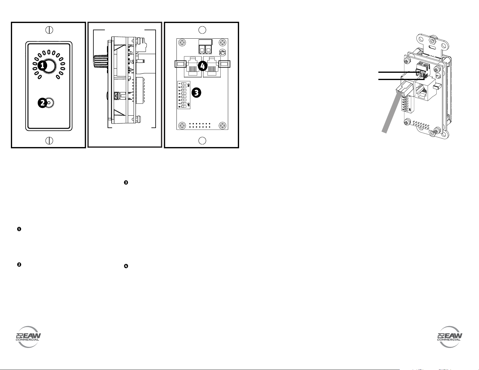
FRONT PANEL FEATURES
ROTARY ENCODER
Use this to adjust the level of the function assigned
to the remote control. A ring of 15 LEDs surrounding
the encoder indicates the relative level.
FUNCTION BUTTON
The function button may be programmed for a
number of actions, such as "Mute an Input" or
"Recall a Priority." When the function is activated,
the LED in the button illuminates. Programming is
done in the Remotes window of DX Navigator.
REAR PANEL FEATURES
ID
This 8-position DIP switch provides 128 (0-127)
unique device IDs read via binary code. Switch 1
is the least significant bit (LSB), and switch 7 is the
most significant bit (MSB). Switch 8 is ignored, but
should be set off. ID '12', for example, would be set
as follows: 0001100. All DIP switches are off except
for three and four.
Each remote control must have the selection switch
set to a unique ID. When the master unit is first
turned on, it polls the REMOTE BUS and identifies the
remote controls connected to it by each unique ID.
CONNECTOR (RJ-25)
Connect the cable from the master unit
(e.g. DX1208) directly to this connector. It should
easily snap in place. The other RJ-25 connector goes
to the next remote. The order of devices or device
IDs is not important. The chain must be a simple
chain (no branches), and must not link back to itself
at any point (no loops).
POWER
The easiest way to power a UR1 remote is
from the master unit over the remote bus cable.
Both jumpers should be installed on J6 and J7
(default).
Alternative power (7-24VDC) may be used
if the power required by the number of remotes
needed exceeds the capability of the master
unit. Connect positive to the 'Alt PWR' screw
terminal and common/0V/ground to the 'GND'
screw terminal.
WARNING: power from the master unit must
be disconnected at an appropriate point by
removing one or more jumpers on J6 and/or
J7. J6 and J7 connect and disconnect VBUS
to the remote on the J1 and J2 modular jacks
respectively.
The alternative power goes directly to
the remote and will also connect to either or
both modular jacks if the respective jumper
is installed. Therefore, it is possible to power
several remotes over the interconnection cable
from the alternative power of one remote.
The maximum current allowed into any
single alternative power connection is 0.4A
(e.g. 9.6W @ 24V, 3.6W @ 9V). This is limited
by a self-resetting fuse at the alternate power
connection terminals in the remote.
Power required: 0.1W 7-24VDC
For example: 4.1mA @ 24VDC, 11.1mA @ 9VDC
Voltage at the remotes must be >7VDC,
even after taking account of any resistive losses
in the cables.
CONNECTION DISTANCES
As connection distances increase, or
cable DC resistance increases, or VBUS
current increases, the VBUS voltage losses
will increase. In many situations, this will be
negligible. Remotes are constant power devices
within their rated voltage, so the current
will increase as the voltage at the remote
decreases. This, in turn, increases cable losses.
As a general guide, if using 24AWG wire,
connected as specified (total resistive loss = 3Ω
per 100 feet of cable - round-trip):
When using 24VDC supply capable of 0.4A
(e.g. DX1208), it can typically support:
• Up to 8W load up to 250 feet*
• Up to 2W load up to 2000 feet*
• Up to 1W load up to 4000 feet*
*The load does not include cable losses.
When using 12VDC supply capable of 0.4A, it
can typically support:
• Up to 4W load up to 150 feet*
• Up to 1W load up to 1000 feet*
*The load does not include cable losses.
J6 J7
39.4 mm / 1.55 in*
49.4 mm / 1.94 in*
*the connector and cable will add
~25 mm / 1 in to the overall depth
Alternative
Power:
+V
Gnd
Remote bus:

Popular Universal Remote manuals by other brands

Memorex CP8 TURBO UNIVERSAL REMOTE CONTROL owner's manual

Memorex

Memorex CP8 TURBO UNIVERSAL REMOTE CONTROL owner's manual

RCA RCU704 Series user guide

RCA

RCA RCU704 Series user guide

Contro l4 C4-SR250-Z-B user guide

Contro l4

Contro l4 C4-SR250-Z-B user guide

One Forall KAMELEON 4 User guide & code book

One Forall

One Forall KAMELEON 4 User guide & code book

One Forall URC-7040 user manual

One Forall

One Forall URC-7040 user manual

One Forall Kameleon URC-9964B00 user guide

One Forall

One Forall Kameleon URC-9964B00 user guide

One Forall URC-2981 Quick & easy set-up guide guide

One Forall

One Forall URC-2981 Quick & easy set-up guide guide

Life Smart SPOT LS034SL user guide

Life Smart

Life Smart SPOT LS034SL user guide

One Forall URC-7930 instruction manual

One Forall

One Forall URC-7930 instruction manual

Philips SRP1103 Specifications

Philips

Philips SRP1103 Specifications

HTD Universal Touch Screen Remote Control owner's manual

HTD

HTD Universal Touch Screen Remote Control owner's manual

Chamberlain 82LM owner's manual

Chamberlain

Chamberlain 82LM owner's manual

Kogan KAUNIRMLCDA user manual

Kogan

Kogan KAUNIRMLCDA user manual

GDI GDLN-800 user manual

GDI

GDI GDLN-800 user manual

Perel CRC1001 user manual

Perel

Perel CRC1001 user manual

Philips SRU8010 Specifications

Philips

Philips SRU8010 Specifications

Ruwido m_8 operating instructions

Ruwido

Ruwido m_8 operating instructions

X10 Wireless MouseRemote UR86A owner's manual

X10

X10 Wireless MouseRemote UR86A owner's manual

manuals.online logo
manuals.online logoBrands
  • About & Mission
  • Contact us
  • Privacy Policy
  • Terms and Conditions

Copyright 2025 Manuals.Online. All Rights Reserved.