Eckman EKETC6 User manual
1
1
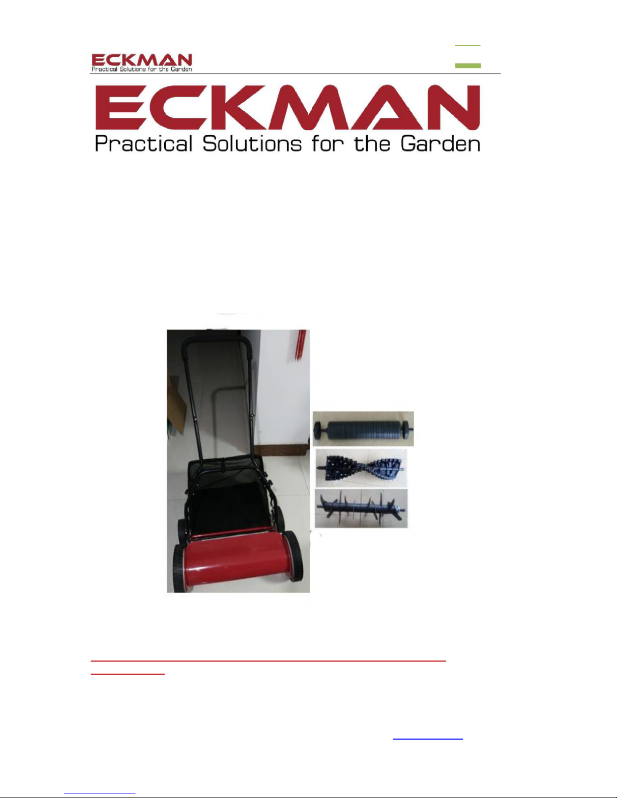
Hand Push Lawn Mower, Lawn Scarifier &
Lawn Aerator
(With Optional Roller) Model EKETC6
Instruction Manual
PLEASE READ AND SAVE THESE INSTRUCTIONS FOR FURTHER
REFERENCE!
ANY QUESTIONS OR PROBLEMS?-Call the ECKMAN Helpline on: 0844 441 3011 or go to www.ECKMAN.co.uk

2
Contents
I. Parts List..................................................................................3-4
II. Specification.....................................................................4
III. Assembly Instructions.......................................................4-8
IV. Safety Guidelines ...........................................................8
V. Height Adjustments........................................................9
VI. Mower Blade Calibration Adjustments.................10-11
VII. Changing Accessory Cassettes......................................11-12
VIII. Guarantee....................................................................12
Exploded View & Parts List.............................................13-14

3
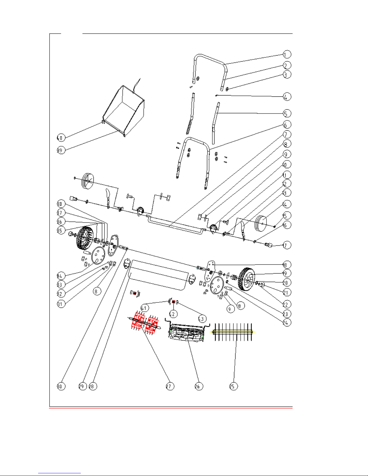
I. Parts List
PART NO.
NAME
QUANTITY
(PCS)
1
Mower cassette
1
2
Aerator cassette
1
3
Scarifier cassette
1
4
Foam padded top handle
1
5
Bar A
2
6
Lower handle
1
7
Bolt 35mm
6
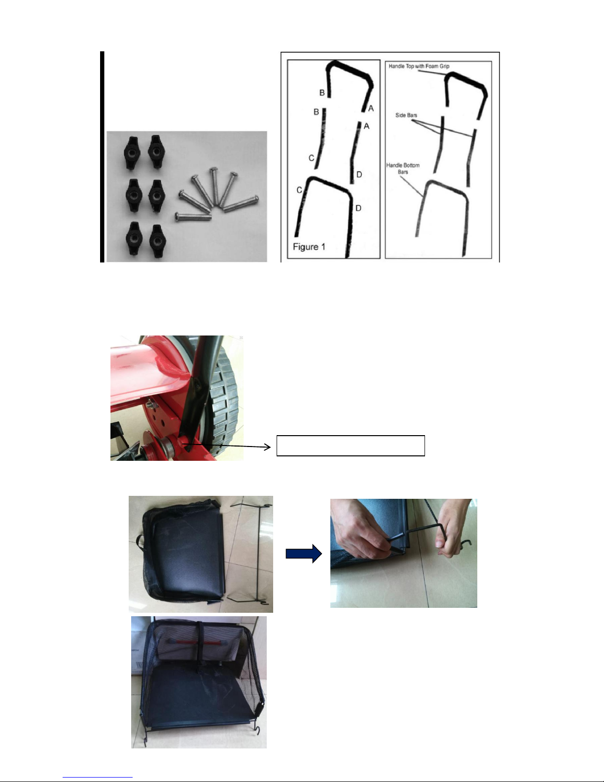
8
Handle connection knob
6
9
Collection bag
1
10
Bag attachment strap
1
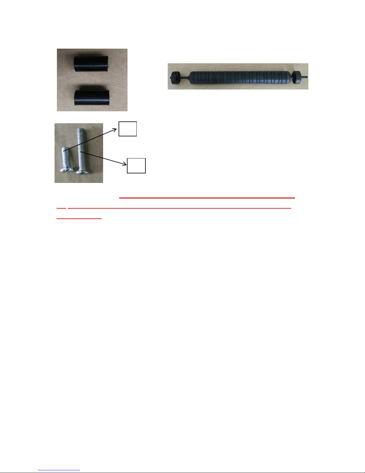
11
Roller spacer tubes
2
12
Roller
1
13
Bolt 25mm
2
14
Bolt 15mm
2
6.Lower
handle
8.Handle connection knob
4.Foam
padded top
handle
9.Collection bag
10.Bag attachment strap
4
BEFORE ASSEMBLY Firstly unpack and check all parts have been supplied. If you think
any parts are missing, first check the packaging again before calling the Eckman helpline
on 0844 441 3011
II. Specifications
Product Name: GRASSHOPPER(3-in-1 Mower/Aerator / Scarifier , With Optional
Roller) Model: EKETC6
Carton Size: 590x480x430mm
Product Size: 570x670x1190 mm
Net weight (with all accessory cassettes): 16.6 kgs
Gross weight: 19.7 kgs
The capacity of collection bag(fabric material) : 30.4 Litres
Working width of accessories 344mm (13 ½”)
Cutting height adjustment range:14-36mm
III. Assembly Instructions
Step 1 Attach the side bars to the handle bottom bars using the knobs, bolts and washers supplied
as illustrated in Figure 1..
Step 2 Attach the handle top with Foam Grip to the Side bars using the knobs, bolts and washers
as illustrated in Figure 1..
11.Roller spacer tubes
12. Roller
13
14
5
Step 3 Attach handle bottom bars to mower by locating the holes at the end of each bottom
bar over the lugs on the mower body. The bottom bars are sprung so this works best if you
first fit one side then push the opposite bottom bar inwards and into place.
Step 4 Bag Assembly (The bag and frame are supplied pre-assembled per illustrations
below.)
Bottom Handle Locating Lugs
6
Step 5 To attach the grass catcher, attach both sides of the support to the metal bar that’s located
at the bottom of the mower by the height adjustment levers (see picture below). Clip
the strap to the hook at the rear of the catcher, loop the strap over the bottom bar of
the handle and push through.. Adjust catcher height as required.
Fully Assembled
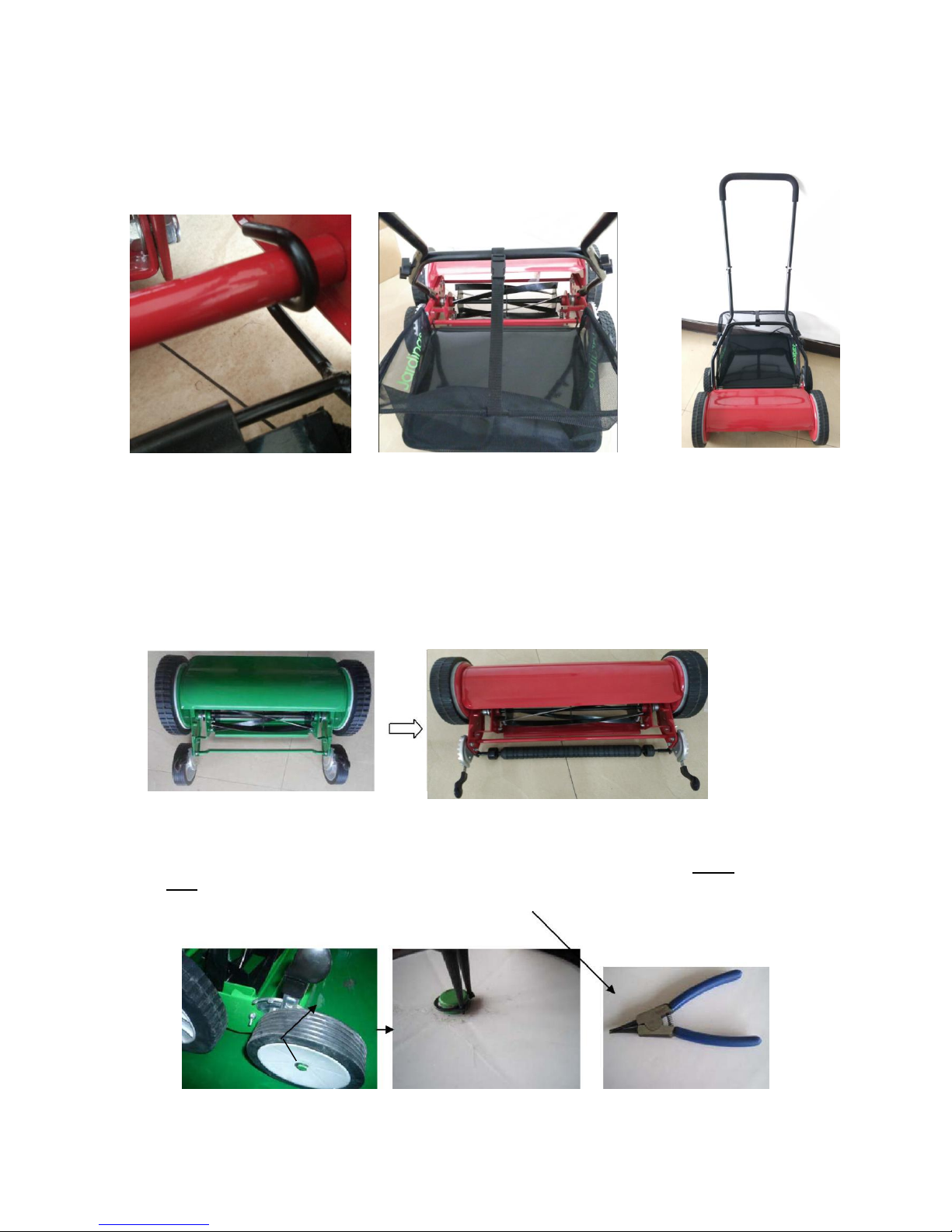
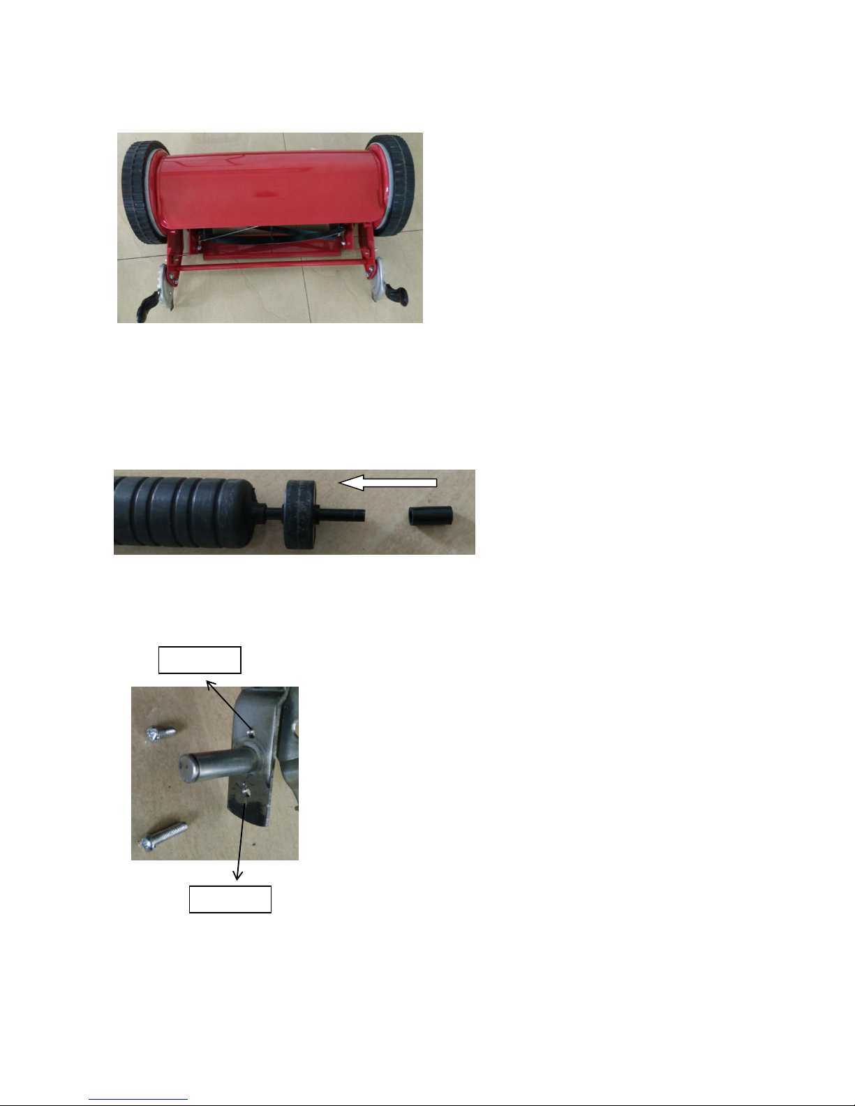
How to assemble roller
Step 1 Take off the two rear wheels’s circlips(see photo as below) using supplied circlip
plier.
circlip
7
Step 2 Remove the wheels.
Step 3 Attach roller.
a. attach roller spacer tubes to the both sides of roller.
b. line up the two holes located on metal bar, long bolt for outer hole, short bolt for inner hole.
c. Fit short bolt to inner hole fully,As this is used for fixing the roller adjustment lever for
roller’s four adjustment levels . Then locate the long bolt just a bit through the outer hole and
attach the roller with roller spacer tubes already fitted to the long bolt. Fully tighten the long
bolt.
Inner hole
Outer hole

8
d. The roller assembled is completed and ready
for operation now .
IV. Safety Guidelines
·Never allow onlookers to place hands, fingers or feet inside any of the accessories
(mower/scarifier/aerator) whilst you are working.
·Take extra care and wear non-slip shoes if using this machine when the grass is wet.
·Do not use the machine whilst barefoot or if wearing sandals.
·Walk slowly, never run.
·Never intentionally strike or ram trees, fences etc. This can cause injuries and severely damage the
machine. Your guarantee will be invalidated.
·Make sure that the equipment is in a safe operating condition before starting work..
-Do not wear loose-fitting clothes when operating this equipment.
-Only work in good lighting conditions.
-Make sure you wear good protective gloves when fitting any of the attachments.
-Do not use this equipment whilst under the influence of alcohol or medication that could make
you drowsy.

9
V. Height Adjustments
1)Wheels height adjustments
The height of the machine above the ground can be adjusted by moving the height adjustment levers
to the required position. To set the lowest position, one at a time pull the adjustment levers located
next to the smaller wheels and move them to their highest position.To set the highest cutting position,
move the adjustment levers one at a time to their lowest position .
NOTE: The two height adjustment levers must be set to the same height positions.
2)Roller height adjustments
The Roller height can be adjusted by moving the height adjustment levers to the required position. This is
same as above wheels height adjustments. The only difference is roller height only has four height
grades,The function of the shorter screw is to prevent the user from setting the adjustment lever on the
fifth height grade or above. (see photos as below)
Adjustment
lever
Lowest position
Highest position
Lowest position
Highest position
Shorter screw
10
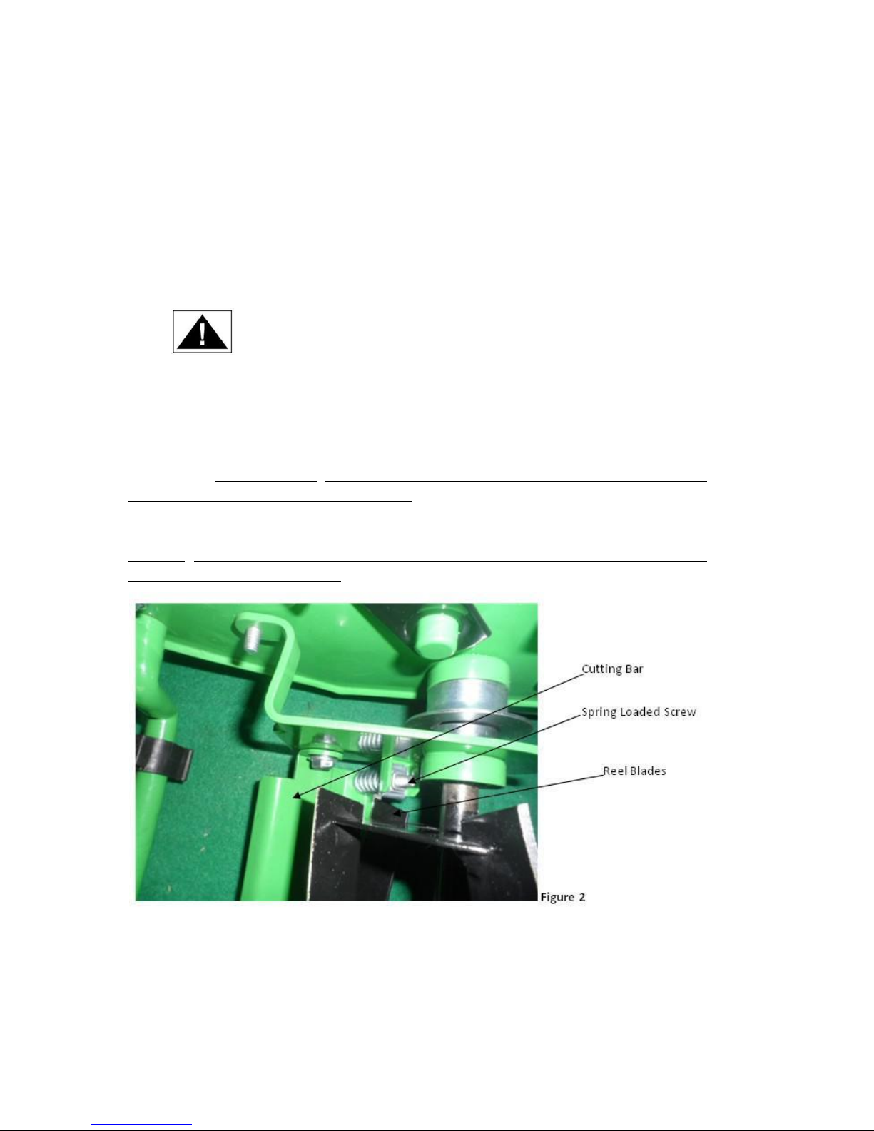
VI. Mower Blade Calibration Adjustments
The blades on the push mower are all calibrated prior to leaving the factory and generally do
not require adjustment .However adjustments may be required only if you notice a rough,
uneven cut; the mower is difficult to push, or the mower simply does not cut the grass. Please
note before proceeding, adjusting the blades is a very sensitive procedure. A turn(adjustment)
of 1/16 is considered a major adjustment! Carefully follow the procedures below.
Proper calibration is achieved when the cutting blades are adjusted so that the rotating cutting
reel ever so slightly comes in even contact along the entire length of the cutting bar
,creating a shearing or scissor-like effect.
WARNING The cutting bar and the rotating reel blades can be damaged if they are
adjusted too close to each other.
1. Loosening the blades
The cutting bar must be moved away from the rotating cutting reel by turning the spring loaded
screws equally counter clockwise. Be sure to loosen both spring loaded screws on both sides of the
mower the same amount of turns (see Figure 2). Use very fine adjustments!
2.Tightening the blades
The cutter bar must be moved closer the cutting reel by turning the spring loaded screws equally
clockwise. Be sure to tighten the spring loaded screws on both sides of the mower the same
amount same of turns(see Figure 2). Use very fine adjustments!
3.Checking the adjustments
a).Turn the mower upside down.

11
b).Insert a piece of paper between the cutter bar and the reel blades and carefully turn the reel blades
by hand.
c).All blades should slice the paper evenly along the entire length of the cutter bar while the reel turns
smoothly.
d).If the mower has an intermittent cut, adjustment should be made to the appropriate sides of the
blades to attain proper cutting action. Remember, only adjust in tiny increments.
4.General care
To extend the life if the equipment, clean, lightly oil and store the machine and accessories during
inclement weather. Minimum care is required to ensure smooth operation. To avoid damage to the
cutting blades, keep the area to be mowed free from any debris like small stones. For best results
regularly apply oil or lubricant to the machine, accessories, bearings and any other moving parts.
WARNING Keep cutter bar free from any debris.
VII. Changing Accessory Cassettes
Fitting and changing accessory cassettes only takes a few moments provided you follow
these instructions. This 3-in-1 machine is supplied with the mower accessory already
fitted.
To remove the mower cassette, first unscrew the two butterfly bolts(see Figure3) (one on
each side of the machine). After removing these two bolts, squeeze the spring loaded
connectors(see Figure 4) inwards with two hands(remember to wear protective
gloves) ,then pull out the mower cassette carefully(see Figure 5). You may find it easier
to first remove the handle and set the adjustable height to maximum.
Butterfly bolt
Figure 4 Spring loaded connector
Figure 3

12
Take off the spring loaded connectors from mower cassette and fit them to aerator cassette or
scarifier cassette, then squeeze the connectors inwards and fit to the slots.
Ensure that both spring-loaded connectors are fully locked in place before attempting to use the
machine.
(All accessory cassettes are held in place with the wheel-drive mechanism via a spring loaded
connector as in the picture below. There must be one spring-loaded connector at each end. These
connectors MUST be fitted each time you fit any cassette.)
Keep all connectors cleaned and well-oiled.
VIII. Guarantee
This product carries a 12 month guarantee from date of purchase for use only within the
domestic environment. This guarantee covers defective parts and faulty workmanship and
not misuse, abuse, using the product for purposes other than those for which it was
Figure 5
Slot

13
intended, or if the product has been modified in any way. Proof of purchase will be
required. Your statutory rights remain unaffected.
Exploded view & Parts list
14

15
Table of contents
Other Eckman Tiller manuals


![Powermate P-RTT-196MD-[E] Operator's manual](/data/manuals/2k/2/2k2fl/sources/powermate-p-rtt-196md-e--manual.jpg "Powermate P-RTT-196MD-[E] Operator's manual")


