6 Safety MAN1177
(07/28/2023)
■ Do not operate equipment while under the inu-
ence of alcohol or drugs.
■ Operate only in daylight or good articial light.
■Keep hands, feet, hair, and clothing away from
equipment while engine is running. Stay clear of
all moving parts.
■Always comply with all state and local lighting
and marking requirements.
■Never allow riders on power unit or attachment.
■Power unit must be equipped with ROPS or
ROPS cab and seat belt. Keep seat belt secure-
ly fastened. Falling off power unit can result in
death from being run over or crushed. Keep
foldable ROPS systems in “locked up” position
at all times.
■Always sit in power unit seat when operating
controls or starting engine. Securely fasten
seat belt, place transmission in neutral, engage
brake, and ensure all other controls are disen-
gaged before starting power unit engine.
■Operate tractor PTO at 540 RPM. Do not exceed.
■Do not operate PTO during transport.
■Connect PTO driveline directly to power unit
PTO shaft. Never use adapter sleeves or adapt-
er shafts. Adapters can cause driveline failures
due to incorrect spline or incorrect operating
length and can result in personal injury or death.
■Look down and to the rear and make sure area is
clear before operating in reverse.
■Use extreme care when working close to fences,
ditches, other obstructions, or on hillsides.
■Do not operate or transport on steep slopes.
■Do not stop, start, or change directions sudden-
ly on slopes.
■Use extreme care and reduce ground speed on
slopes and rough terrain.
■Watch for hidden hazards on the terrain during
operation.
■Stop power unit and equipment immediately
upon striking an obstruction. Turn off engine,
set parking brake, remove key, inspect, and re-
pair any damage before resuming operation.
■Before performing any service or maintenance,
disconnect driveline from tractor PTO.
■Before dismounting power unit or perform-
ing any service or maintenance, follow these
steps: disengage power to equipment, lower
the 3-point hitch and all raised components to
the ground, operate valve levers to release any
hydraulic pressure, set parking brake, stop en-
gine, remove key, and unfasten seat belt.
■Never go underneath equipment (lowered to the
ground or raised) unless it is properly blocked
and secured. Never place any part of the body
underneath equipment or between moveable
parts even when the engine has been turned off.
Hydraulic system leak down, hydraulic system
failures, mechanical failures, or movement of
control levers can cause equipment to drop or
rotate unexpectedly and cause severe injury or
death. Follow Operator’s Manual instructions
for working underneath and blocking require-
ments or have work done by a qualied dealer.
MAINTENANCE
■Service and maintenance work not covered in
OWNER SERVICE must be done by a qualied
dealership. Special skills, tools, and safety pro-
cedures may be required. Failure to follow these
instructions can result in serious injury or death.
■Before performing any service or maintenance,
disconnect driveline from tractor PTO.
■Before dismounting power unit or perform-
ing any service or maintenance, follow these
steps: disengage power to equipment, lower
the 3-point hitch and all raised components to
the ground, operate valve levers to release any
hydraulic pressure, set parking brake, stop en-
gine, remove key, and unfasten seat belt.
■Never go underneath equipment (lowered to the
ground or raised) unless it is properly blocked
and secured. Never place any part of the body
underneath equipment or between moveable
parts even when the engine has been turned off.
Hydraulic system leak down, hydraulic system
failures, mechanical failures, or movement of
control levers can cause equipment to drop or
rotate unexpectedly and cause severe injury or
death. Follow Operator’s Manual instructions
for working underneath and blocking require-
ments or have work done by a qualied dealer.
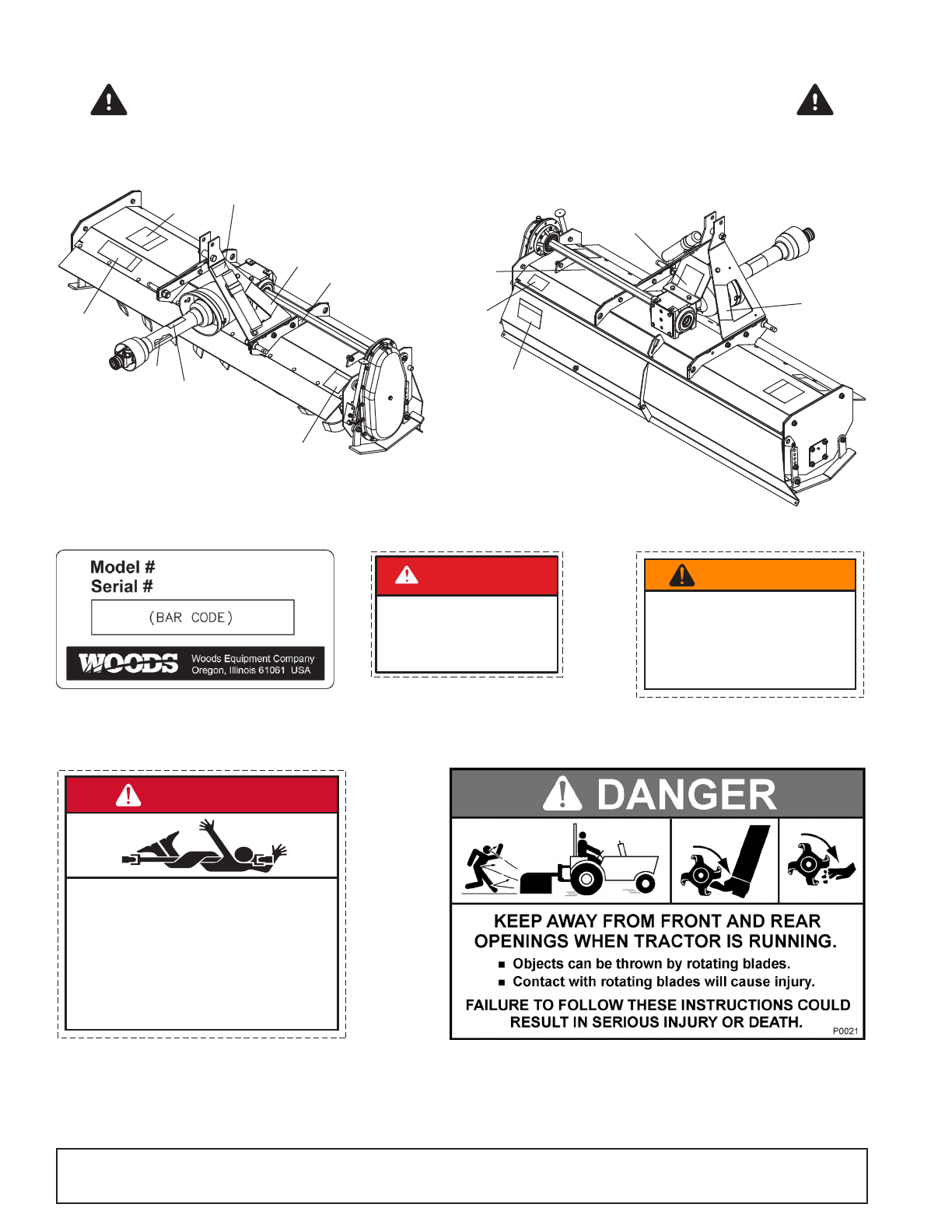
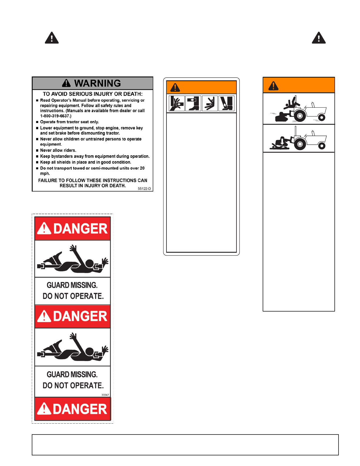
SAFETY RULES
ATTENTION! BECOME ALERT! YOUR SAFETY IS INVOLVED!