Eclipse TD508MK3 User manual

JAPANESE
GERMAN FRENCH ITALIAN SPANISH
ENGLISH
MANUAL No. 090003-32270700
・Thank you for purchasing this product.
・Please read this owner's manual thoroughly prior to carrying out installation and connections.
・Depending on the specific installation specialised skills maybe required. In such a case, please consult a
qualified technician.
・Installation by two people is always advised.
Keep this Owner’s Manual together with the Warranty Certificate in a safe place for later reference.
OWNER'S MANUAL

− 28 −
ENGLISH GERMAN FRENCH ITALIAN SPANISH
Parts listParts list Check that all of the following items are present
*This speaker has been designed around the Time Domain concept.
《What is Time Domain theory?》
The theory seeks to accurately reproduce the timing of the air and sound movement exactly, as if were present in
the original recording. The difference is you feel the sense of ‘being there’ at the original sound recording. We could
only achieve this experience using our unique technology.
Time domain theory is an audio theory proposed by Hiroyuki Yoshii, the President of TIMEDOMAIN Corporation.
Speaker
×1
Hexagonal wrench
(large) ×1
Hexagonal wrench
(small) ×1
Logo sticker
×1
Owner’s Manual
×1
Warranty
×1
Grille
×1
Plug
×5
Included with
TD510MK2 only
Contents
Parts list 28
Safety guidelines 29
Checklist before use 29
Speaker installation example 30
Parts and connections 31
Adjusting the speaker angle 32
Installing the speaker grille 33
On a floor or shelf 34
On a ceiling or wall 37
Care / Specifications 48
Warranty and After Service 49
Bracket installation positioning template 51
Contents
Before
installation
Installation

− 29 −
GERMAN FRENCH ITALIAN SPANISHENGLISH
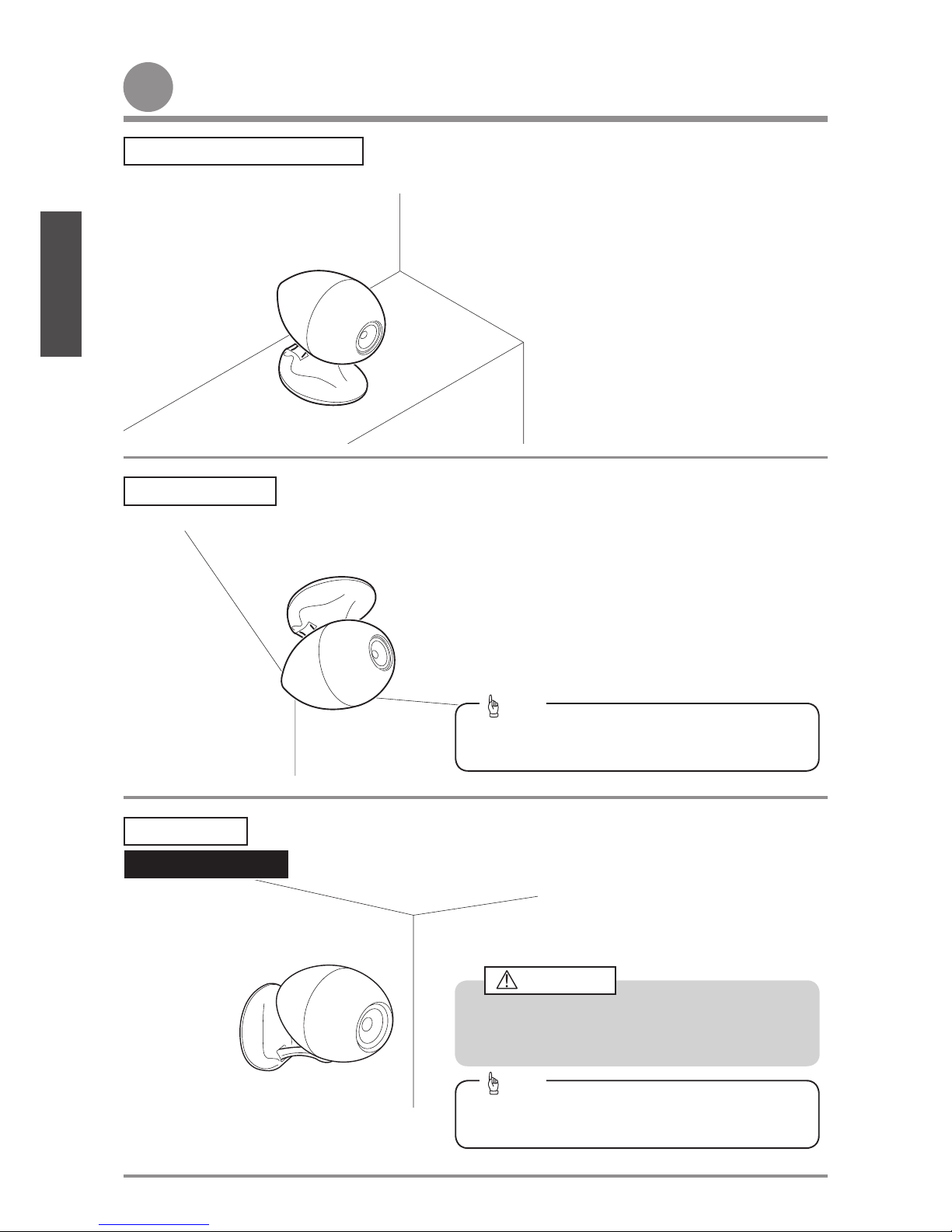
Checklist before useChecklist before use
Safety guidelinesSafety guidelines
Caution
・The unit should be placed on a hard, flat surface. Placing the unit on an unstable surface may cause it to fall over and cause
injury.
・Do not climb on or swing from the unit. In particular, care should be exercised when children are present. The unit may fall or
break and cause injury.
Warning
・Do not open the unit as this may cause electric shock or injury. For repair or maintenance, please contact a Customer Service
Center. Do not attempt to modify the unit. This may cause fire or electric shock, and invalidate the warranty.
・Do not place the unit in the bathroom or anywhere exposed to rain. Do not use the unit in places with high humidity. This may
cause fire or electric shock. Be particularly careful when using the unit in rainy weather or when it is snowing, at the beach or near
water. Do not place above or near the unit, any flower vases, plant pots, cups, makeup, medicine or any vessel containing liquid
or any small metal objects. In case any liquid or small metal objects enter the unit, fire or electric shock may result.
・Be sure to set the volume to the minimum level before turning on the power supply for connected equipment and before switching
the input source. Sudden high levels of output can cause damage to the connected speaker system.
・Even pleasant music can be a disturbance at times. To avoid disturbance in your neighborhood, enjoy your unit at an appropriate
volume. Remember that at night, even low volume carries into surrounding areas. Help to maintain a pleasant living environment.
・Always be sure to turn off the power supply for the connected equipment before connecting the speaker.
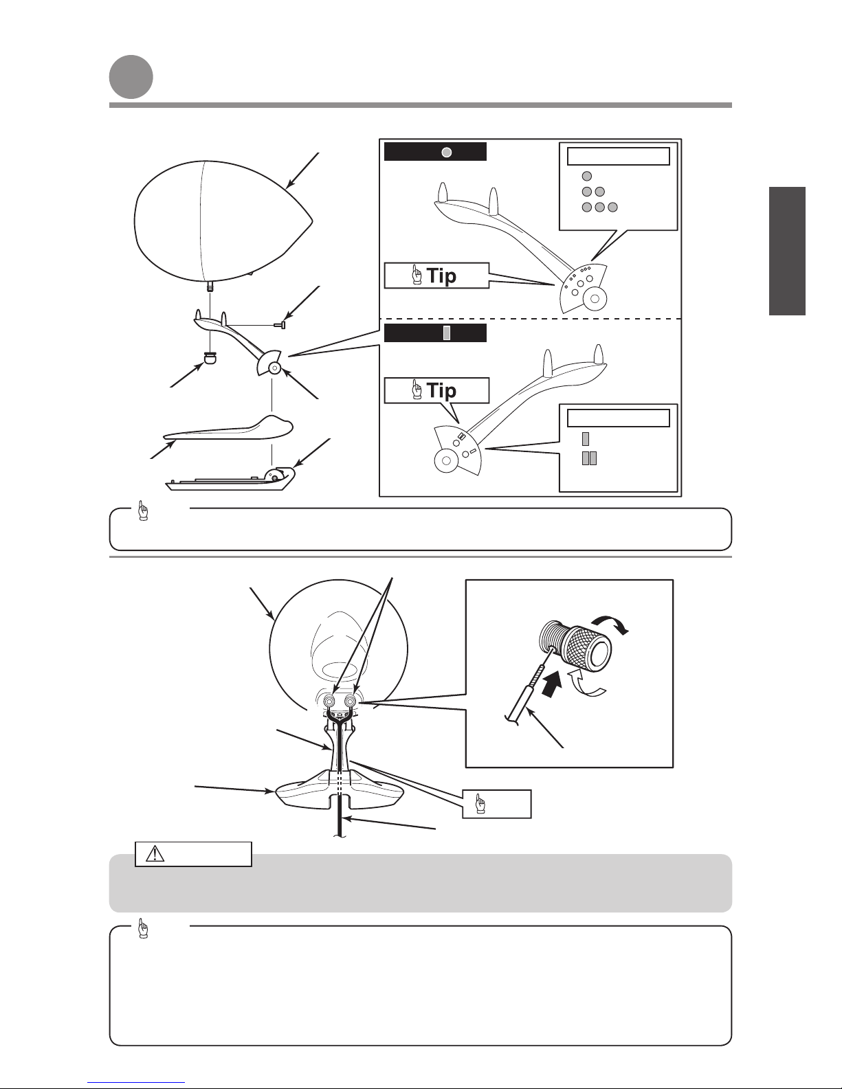
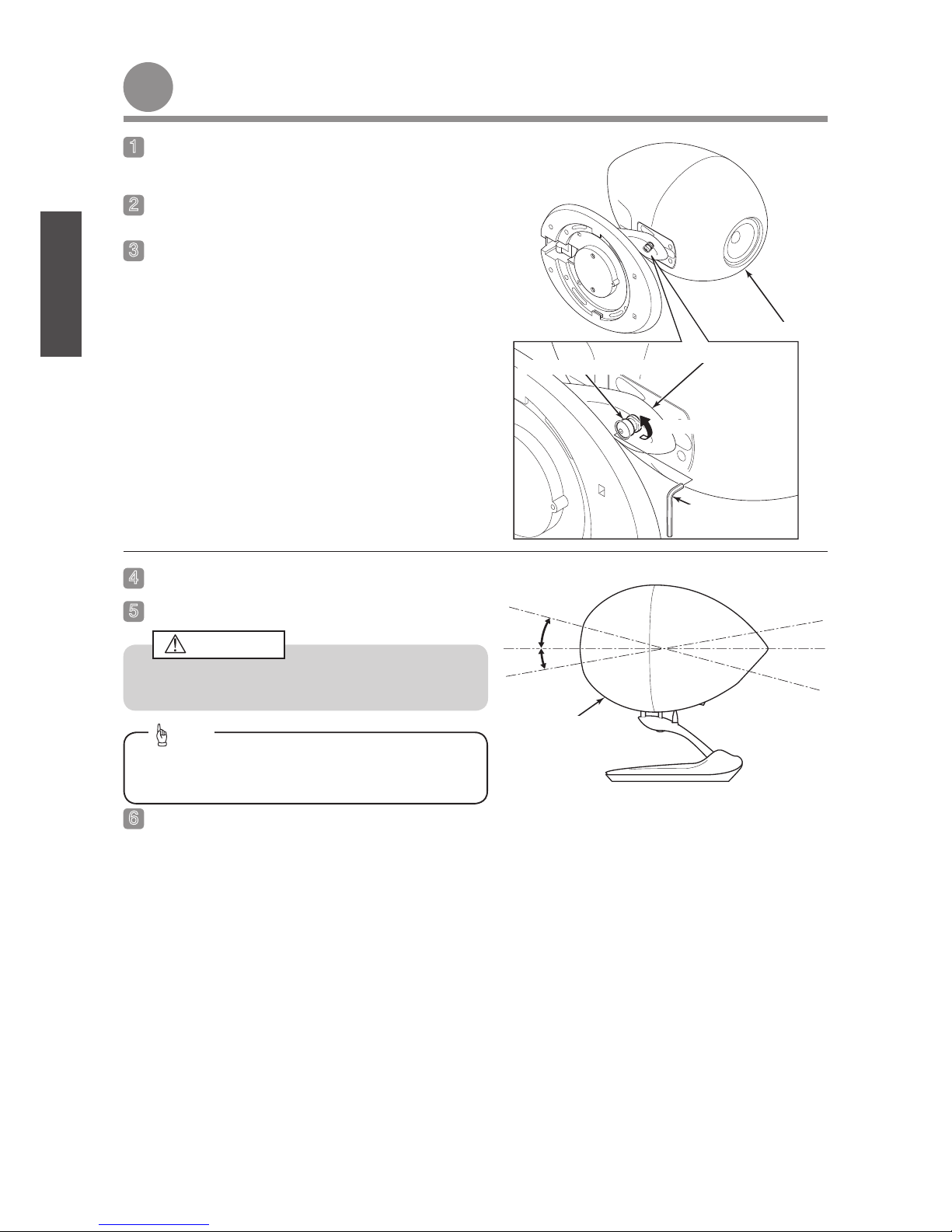
・Be careful not to tip over the stand.
・Clean the unit by wiping it gently with a soft cloth moistened in neutral detergent. Do not use liquid solvents such as alcohol or
thinner to clean this product.
The following WARNING and CAUTION signs are used throughout this owner’s manual as well as on the product.
These signs alert the installer and users of important safety information to avoid risk of injury and damages to the
product. Make sure that you understand these signs thoroughly before reading this manual.
Warning
The instructions which follow this sign indicate situations where failure to follow the
instructions may result in death or severe injury.
Caution
The instructions which follow this sign indicate situations where failure to follow the
instructions could cause injury when using the product or physical damage to equipment
and surroundings.
Tip This section contains information that can help to prevent problems and damage to the
unit, and also contain other useful information.

− 30 −
ENGLISH GERMAN FRENCH ITALIAN SPANISH
Speaker installation exampleSpeaker installation example
Installation on a floor or shelf ・Make fine adjustments to the speaker angle. Refer to P.32.
・Adjust the angle of the speaker arm. Refer to P.34.
・Installation summary Refer to P.37.
・Determine the speaker installation angle. Refer to P.38 - 39.
・Install the speaker on the ceiling. Refer to P.41 - 47.
・Make fine adjustments to the speaker angle. Refer to P.32.
TD508MK3 only
Ceiling installation
Wall mounting ・Installation summary Refer to P.37.
・Determine the speaker installation angle. Refer to P.40.
・Install the speaker on the wall. Refer to P.41 - 47.
・Make fine adjustments to the speaker angle. Refer to P.32.
The only speaker which can be installed on a wall is the
TD508MK3. The TD510MK2 cannot be installed on a
wall.
Caution
The CB1 mounting bracket available separately should
be used to provide the most flexible installation.
Tip
The CB1 mounting bracket available separately should
be used to provide the most flexible installation.
Tip

− 31 −
GERMAN FRENCH ITALIAN SPANISHENGLISH
Parts and connectionsParts and connections
※The diagrams are for the TD508MK3 are the same for the TD510MK2.
Speaker cable
Speaker cable
(diameter less than φ7 mm)
Speaker arm
Speaker base
Speaker input terminals
Speaker angle adjustment nut
Speaker base cover
Speaker base
Side with mark
2 main positions
:Default
Speaker arm
3 main positions
Side with mark
Hexagonal head screw
Speaker
Speaker
When connecting the speaker wires, insert the bare ends of the speaker wires correctly so that they do not touch
neighboring terminals, otherwise it may cause short-circuits.
Caution
The marks on the speaker arm can be used as a guide when adjusting the angle of the speaker arm.
Tip
For speaker cable diameter φ7 mm or less
If the speaker cable is passed through the cable holes in the speaker base and the speaker arm, it will improve
the outer appearance of the speaker.
For speaker cable diameter φ7 mm or more
The speaker cable cannot be passed through the speaker arm, so route it along the outside.
Tip
Tip

− 32 −
ENGLISH GERMAN FRENCH ITALIAN SPANISH
Adjusting the speaker angleAdjusting the speaker angle
Speaker angle adjustment nut
Loosen the speaker angle adjustment nut on the under
side of the speaker arm.
Stand the speaker upright.
Adjust the speaker to the desired angle.
Spread a soft cloth over the floor in order to prevent
damaging the surface of the speaker.
Place the speaker on its side.
Be careful not to let the speaker stand fall over while
adjusting the angle.
Caution
Securely tighten the speaker angle adjustment nut.
Speaker
+15°
-10°
Speaker
Loosen
Speaker arm
Hexagonal wrench
(large)
The angle of the speaker can be adjusted within the
range of +15° to -10°.
Tip

− 33 −
GERMAN FRENCH ITALIAN SPANISHENGLISH
Installing the speaker grilleInstalling the speaker grille
Grille
Install the grille as shown in the illustration.
TD510MK2 only
Install the plugs as indicated.
Speaker
Speaker
Plugs X5
・The grille may be attached when the speaker is not
in use or at the users discretion.
・Clip the edge of the grille to secure it.
Tip

− 3 −
ENGLISH GERMAN FRENCH ITALIAN SPANISH
On a floor or shelfOn a floor or shelf
Screws X4
Speaker base cover
Safety cable
Remove the screws from the bottom of the speaker base
and keep to hand for use later.
Stand the speaker upright.
Remove the cover from the speaker base.
Remove the safety cable from the speaker base.
Speaker base
Screwdriver
Spread a soft cloth over the floor in order to prevent
damaging the surface of the speaker.
Place the speaker on its side.
-
Adjusting the angle of the speaker arm
-
Speaker
Speaker
Speaker base
Screw
Screwdriver
Keep screws to hand for use later.
Tip
・If you wish to use the speaker at the standard angle position (as it is when removed from its packaging), there is
no need to adjust the angle.
・You can increase the speaker angle by 15° from its standard position (as it is when removed from its packaging)
by adjusting the speaker arm. (The angle of the speaker [including fine adjustmentsrefer to P.32] can be
adjusted by up to a maximum of +30°.)
Tip

− 35 −
GERMAN FRENCH ITALIAN SPANISHENGLISH
Speaker arm side with
mark
Remove the retaining bolt and the angle adjustment bolt
from the speaker arm side with the mark.
Install the retaining bolt to the speaker arm side with the
mark.
Set the angle of the speaker arm so that it is aligned with
the mark, and then tighten the angle adjustment bolt.
Mark:
Speaker arm
Speaker arm side with mark
Angle adjustment bolt
Speaker cone
Speaker
Speaker
Speaker cone
・When the retaining bolt and locking screw have been
removed, ensure the speaker does not fall forwards
so neither the cone or cabinet is damaged.
・Be careful not to get your hand or fingers caught in
the movable part of the speaker arm.
Caution
・When the retaining bolt and locking screw have been
removed, ensure the speaker does not fall forwards
so neither the cone or cabinet is damaged.
・Be careful not to get your hand or fingers caught in
the movable part of the speaker arm.
Caution
Speaker arm
Retaining bolt
Angle adjustment bolt
Angle
adjustment
bolt
Fixing holes
Hexagonal wrench
(small)
Hexagonal wrench
(large)
Spread a soft cloth over the floor in order to prevent
damaging the surface of the speaker.
Place the speaker on its side.
The fixing holes at the and marks on the
speaker arm will not be used.
Tip
Remember to refit the locking bolt after adjusting the
angle.
Tip
The fixing hole at the mark on the speaker arm will
not be used.
Tip
Retaining bolt
Retaining bolt

− 36 −
ENGLISH GERMAN FRENCH ITALIAN SPANISH
Replace the safety cable, fixing to the base as shown.
Install the cover over the speaker base.
Install the screws from the bottom of the speaker base.
Spread a soft cloth over the floor in order to prevent
damaging the surface of the speaker.
Place the speaker on its side.
Speaker
Speaker
Speaker base
Speaker base
Screw
Speaker base cover
Stand the speaker upright.
Screws X4
Safety cable

− 37 −
GERMAN FRENCH ITALIAN SPANISHENGLISH
On a ceiling or wallOn a ceiling or wall (The bracket (CB1) which is sold separately is required.)
Bracket
(included with the CB1)
Spacer
(included with the CB1)
For speaker cable diameter φ7 mm or more
For speaker cable diameter φ7 mm or less
Caution
Space
This product can be installed on ceilings and walls. If installing on a ceiling or a wall, you will need to use extra screws
(sold separately). When installing the speaker, be sure to fit the safety cable (included with the CB1).
Safety cable
(included with the CB1)
Base cover
Speaker
Speaker base
Space
Leave enough space so that the rear of speaker does not touch the ceiling or wall.
Caution
・Please read this owner's manual thoroughly prior to carrying out installation and connections.
・Depending on the specific installation specialised skills maybe required. In such a case, please consult a
qualified technician.
・Installation by two people is always advised.
・Please note the screws for fixing the product and safety cable to the ceiling are NOT supplied.
Caution
Wall
Ceiling
Screw
(sold separately)

− 38 −
ENGLISH GERMAN FRENCH ITALIAN SPANISH
Alignment mark:
If the speaker angle is 0°
Alignment mark:
−30°
−15°
-
Installing on a ceiling (installation example)
-
Speaker arm : Standard Fixing holes:Side with mark
(Mark:)
0°
Standard speaker arm type
Alignment mark:
If the speaker angle is -15° Speaker arm : Standard
If the speaker angle is -30° Speaker arm : Standard
Fine adjustment range:−15° ~10°
(Refer to P.32.)
Fine adjustment range:−30° ~−5°
(Refer to P.32.)
Fine adjustment range:−45° ~−20°
(Refer to P.32.)
Select an installation method for the speaker arm in
accordance with the speaker installation angle that will
be used at the installation location.
Install the speaker on the ceiling.
Speaker
Speaker base
Speaker arm
Fixing holes:Side with mark
(Mark:)
Fixing holes:Side with mark
(Mark:)
・The installation angle can be varied within a wide
range by means of the direction of the speaker arm
and the fixing holes used.
・For examples of the speaker angles, refer to the
installation examples on pages 38 and 39.
・
The position of the fixing hole (mark) is important
when assembling the speaker and the speaker arm.
For details, refer to “Assembling the speaker” on P.46.
Tip
For details on the installation procedure, refer to P.41 -
47.
Tip
Fixing holes
Fixing holes
Fixing holes

− 39 −
GERMAN FRENCH ITALIAN SPANISHENGLISH
Alignment mark:
Alignment mark:
Alignment mark:
−30°
−45°
−60°
Reverse speaker arm type
If the speaker angle is -30° Speaker arm : Reverse
If the speaker angle is -45° Speaker arm : Reverse
If the speaker angle is -60° Speaker arm : Reverse
Fine adjustment range:−45° ~−20°
(Refer to P.32.)
Fine adjustment range:−60° ~−35°
(Refer to P.32.)
Fine adjustment range:−75° ~−50°
(Refer to P.32.)
Speaker
Speaker base
Speaker arm
Be careful not to get your hand or fingers caught in the
movable part of the speaker arm.
Caution
Fixing holes:Side with mark
(Mark: )
Fixing holes:Side with mark
(Mark:)
Fixing holes:Side with mark
(Mark:)
The position of the fixing hole (mark) is important when
assembling the speaker and the speaker arm. For
details, refer to “Assembling the speaker” on P.46.
Tip
Fixing holes
Fixing holes
Fixing holes

− 0 −
ENGLISH GERMAN FRENCH ITALIAN SPANISH
角度調整ボルト穴
30°
45°
60°
-
Installing on a wall (installation example)
-
If the speaker angle is 30° Speaker arm : Reverse
If the speaker angle is 45° Speaker arm : Reverse
If the speaker angle is 60° Speaker arm : Reverse
Alignment mark:
Alignment mark:
Alignment mark:
For the TD508MK3
Fine adjustment range:20° ~45°
(Refer to P.32.)
Fine adjustment range:35° ~60°
(Refer to P.32.)
Fine adjustment range:50° ~75°
(Refer to P.32.)
Speaker
Speaker base
Speaker arm
Select an installation method for the speaker arm in
accordance with the speaker installation angle that will
be used at the installation location.
Install the speaker on the wall.
The only speaker which can be installed on a wall is the
TD508MK3. The TD510MK2 cannot be installed on a wall.
Caution
Fixing holes:Side with mark
(Mark: )
Fixing holes:Side with mark
(Mark:)
Fixing holes:Side with mark
(Mark:)
・If installing the speaker on a wall, the direction of the
speaker arm is reversed.
・The position of the fixing hole (mark) is important
when assembling the speaker and the speaker arm.
For details, refer to “Assembling the speaker” on P.46.
Tip
For details on the installation procedure, refer to P.41 - 47.
Tip
Fixing holes
Fixing holes
Fixing holes

− 1 −
GERMAN FRENCH ITALIAN SPANISHENGLISH
Hexagonal wrench
(large)
Remove the screws from the bottom of the speaker base
and the speaker angle adjustment nut from the speaker
arm.
Rear view of the speaker
Spread a soft cloth over the floor in order to prevent
damaging the surface of the speaker.
Place the speaker on its side.
Retain the adjustment nut as it will be required to lock
the unit in position.
Caution
Remove the hexagonal head bolt from the speaker arm.
-
Preparation for installation
-
Speaker
Speaker arm
Speaker arm
Screwdriver
Speaker angle adjustment nut
Speaker base
Speaker angle adjustment nut
Hexagonal head bolt
Hexagonal head bolt
Hexagonal wrench
(small)
Screws X4
The hexagonal head bolt which is removed will be used
later, so be careful not to lose it.
Tip
The 4 cover retaining screws can be kept with the
packing for future use.
Tip

− 2 −
ENGLISH GERMAN FRENCH ITALIAN SPANISH
Remove the base cover.
Lift up the speaker to remove it from the speaker arm.
Speaker
Speaker
Speaker base
Speaker arm
Stand the speaker upright.
Remove the safety cable from the speaker base.
・The speaker is heavy, so hold it firmly while removing
it from the speaker arm.
・After removing the speaker, place it on a surface that
will not mark it or allow it to roll around.
Caution
Speaker base cover
Screw
Screwdriver
Remember to retain the screw as it will be used later.
Tip
Safety cable

− 3 −
GERMAN FRENCH ITALIAN SPANISHENGLISH
Screw
(included
with the
CB1) Safety cable
(included with the CB1)
Fixing point
Remove the retaining bolt and the angle adjustment bolt,
and then lift the speaker arm from the speaker base.
Install the safety cable to the bottom of the speaker. Screwdriver
Speaker arm
Speaker base
Front
Be careful not to get your hand or fingers caught in the
movable part of the speaker arm.
Caution
Safety cable
(included with the CB1)
・Pass the safety cable from the speaker front side into
the wire fixing point.
・TD508MK3 speakers only: Use the screw (binding
M5 x 8) that is included with the bracket.
・TD510MK2 speakers only: Use the screw (binding
M4 x 8) that is included with the bracket.
Make sure that the screw installation holes are
correct.
・Securely connect the safety cable to the speaker to
prevent the speaker from falling down.
・Place the speaker on top of the soft cloth while
working so as not to damage the speaker.
Caution
Angle adjustment bolt
Hexagonal wrench
(small)
Hexagonal wrench
(large)
The retaining bolt and angle adjustment bolt will be
used later, so keep them to hand.
Tip Retaining bolt

− −
ENGLISH GERMAN FRENCH ITALIAN SPANISH
Template
Speaker installation position
Screws (sold separately)
Attach to the surface without the
[] mark.
-
Installing the bracket
-
Use the template in the back of this manual to determine
the speaker installation position on the ceiling, and
attach the template to the ceiling with tape.
Use an awl or similar tool to mark the positions of the
bracket mounting holes.
Remove the template from the ceiling.
Peel off the backing paper from the double-sided tape on
the spacer, and then attach the spacer to the bracket.
Attach the bracket to the spacer installation position with
the correct screws for the location.
Route the speaker cable.
・Securely install the bracket to prevent the speaker
from falling down.
・The screws which are used to install the bracket to
the ceiling or wall are not provided with the bracket,
so purchase them separately.
・When securing the bracket to the ceiling or wall
with the screws, if the screws are overtightened, the
bracket may become bent and it may not be possible
to install the speaker. Be careful not to overtighten the
screws.
Caution
Bracket
(included with the CB1)
Bracket
(included with the CB1)
Bracket
(included with the CB1)
Spacer
(included with the CB1)
Spacer
(included with the CB1)
View A
About 1 m
For speaker cable
diameter φ7 mm or
more (sold separately)
For speaker cable diameter
φ7 mm or less (sold separately)
The illustration shows the speaker being installed on a ceiling, but carry out the same procedure if installing the
speaker to a wall.
Tip
Use scissors or similar to cut the template.
Tip
・When installing the bracket to the ceiling or wall, vary
the positions and number of screws used in accordance
with the strength of the ceiling or wall and the locations
of beams.
・If the installation location is not strong enough when
the standard installation holes are made, install more
screws using the slits marked with in order to
increase the installation strength.
Standard installation holes
Bracket
(included with the CB1)
Slits X3
Tip
・Leave an excess length of about 1 m when routing
the speaker cable in order to make it easier to
connect the speaker cable to the speaker.
■For speaker cable diameter φ7 mm or less
If you route the speaker cable inside the bracket, it
will improve the outer appearance of the speaker.
Tip

− 5 −
GERMAN FRENCH ITALIAN SPANISHENGLISH
Align the projections on the
speaker with the slots in the bracket
(included with the CB1).
Screws (included with the CB1) X4
Route the speaker cable.
Insert the tabs on the speaker base into the grooves in
the bracket.
Turn the speaker base to hook the tabs on the speaker
base into the bracket.
Securely install the speaker base to the bracket.
Mark
Speaker base
Speaker base
Speaker base
Speaker base
Screwdriver
Screwdriver
Speaker base
Bracket
(included with the CB1)
Bracket
(included with the CB1)
Bracket (included with the CB1)
Bracket
(included with the CB1)
・Loosen the screws of the speaker base, and then turn
the speaker base to the left or right in steps of 10° to
adjust.
・When adjusting the direction of the speaker base,
never remove the screws, otherwise the speaker
base may fall down.
Caution
・Align the tabs on the speaker base and the grooves
in the bracket, and then securely fit the speaker base
onto the bracket. If the speaker base and the bracket
are not securely locked together, there is the danger
that the speaker base may fall down.
・Be careful not to clamp the speaker cable with the
speaker base, the bracket or the ceiling.
Caution
Screws (included with the CB1) X4
For speaker cable diameter
φ7 mm or less (sold separately)
Cable holes
■For speaker cable diameter φ7 mm or less
If the speaker cable is passed through the cable
holes in the speaker base, it will improve the outer
appearance of the speaker.
Tip
When securing the speaker to the bracket, turn the
speaker base in the direction of the arrow marked on
the speaker base to secure it. The illustration shows the
TD508MK3.
Tip

− 6 −
ENGLISH GERMAN FRENCH ITALIAN SPANISH
Speaker angle
adjustment nut
If installing the speaker arm to the speaker
base in the standard position
Angle adjustment bolt
Insert the locking pin of the speaker into the hole in
the speaker arm, and then secure it by tightening the
speaker angle adjustment nut.
-
Assembling the speaker
-
Assemble the speaker arm to the speaker base.
Grooves X3
Pins X3
Locking pin
Tighten the retaining bolt and the angle adjustment bolt.
Make fine adjustments to the speaker angle.
Tighten the hexagonal head bolt into the speaker arm.
Hexagonal head bolt
Safety cable
(included with the
CB1)
Speaker
Speaker
Speaker
Speaker arm
Speaker base
Speaker arm
Speaker base
Speaker arm
Be careful not to get your hand or fingers caught in the
movable part of the speaker arm.
Caution
Be careful not to get your hand or fingers caught in the
movable part of the speaker arm.
Caution
If installing the speaker arm to the speaker
base in the reverse position
Angle adjustment bolt
Insert the locking pin into the hole in the speaker
arm, and align the three pins with the grooves in the
speaker.
Tip
・Adjust the angle of the speaker when installing the
speaker arm.
・When adjusting the angle of the speaker, refer to
P.38 – 40 for details of the mark alignment positions.
Tip
Securely tighten the retaining bolt and the angle
adjustment bolt.
Tip
For details on making fine adjustments to the speaker
angle, refer to “Adjusting the speaker angle” on P.32.
Tip
Retaining bolt
Retaining bolt
This manual suits for next models
1
Table of contents
Other Eclipse Speakers manuals

Eclipse
Eclipse SE8235 User manual

Eclipse
Eclipse TD712z MK2 User manual

Eclipse
Eclipse 512 User manual

Eclipse
Eclipse TD307MK2A User manual

Eclipse
Eclipse 508DMK3 User manual

Eclipse
Eclipse TD508II User manual

Eclipse
Eclipse D3II User manual

Eclipse
Eclipse D5II Quick start guide

Eclipse
Eclipse TD508II User manual

Eclipse
Eclipse TD510ZMK2 User manual
Popular Speakers manuals by other brands

Polk Audio
Polk Audio SURROUNDBAR quick start guide

Krix
Krix HEMISPHERIX A20 installation guide

DLS
DLS PA6.20 user manual

TAG MCLAREN AUDIO
TAG MCLAREN AUDIO Proteus F1-CA AvantGarde owner's manual

ENERGY SISTEM
ENERGY SISTEM home speaker4 user manual

Miller & Kreisel Sound
Miller & Kreisel Sound LCR-750THX Operation manual