manuals.online logo
Brands
  1. Home
  2. •
  3. Brands
  4. •
  5. Meyer Sound
  6. •
  7. Speakers
  8. •
  9. Meyer Sound MSL-2A User manual

Meyer Sound MSL-2A User manual

Meyer Sound Laboratories, Inc.
2832 San Pablo Avenue
Berkeley, CA 94702
MSL-2A
Reinforcement
Loudspeaker Operating Instructions
The MSL-2A is designed to be operated as a
system with the Meyer Sound S-1 Control Elec-
tronics Unit (one S-1 per channel). The S-1
comprises electronic crossover, Meyer Sound
exclusive MultiSense™ driver protection cir-
cuitry with excursion protection, and amplitude
and phase response alignment circuitry opti-
mized for the loudspeaker.
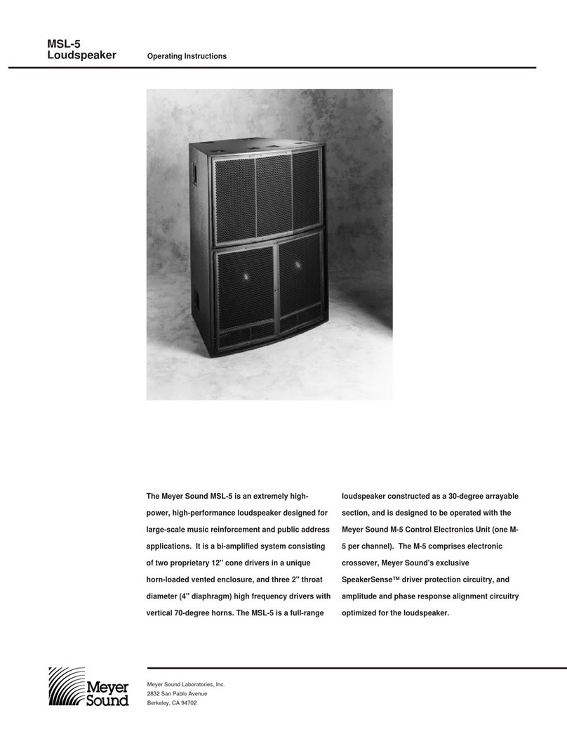
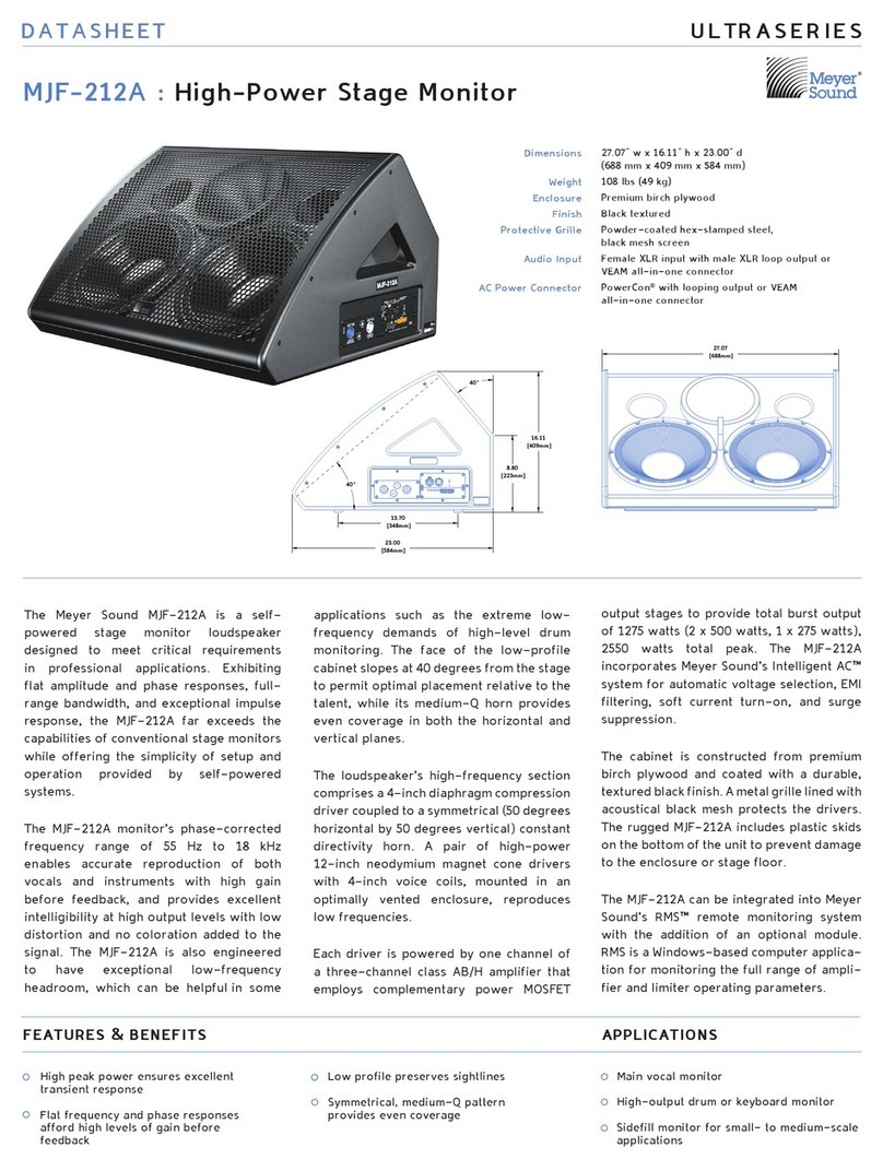
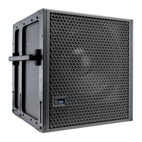
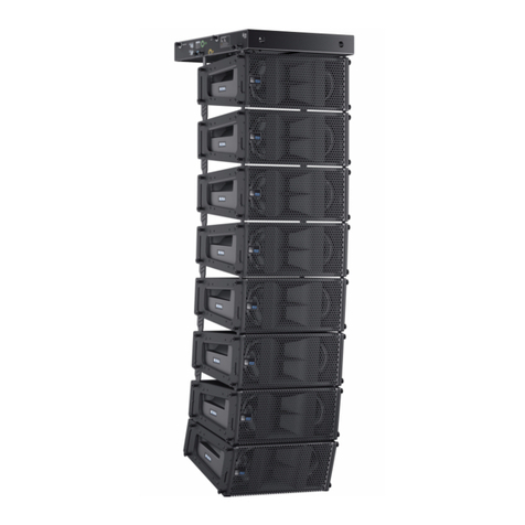
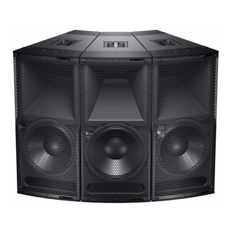
The Meyer Sound MSL-2A is a high-powered,
wide coverage loudspeaker for professional
sound reinforcement applications. Specifically
designed for touring reinforcement, the accu-
rate, rugged MSL-2A is a biamplified system
consisting of a proprietary 15-inch low-fre-
quency driver in a vented enclosure, and a 70-
degree high-frequency horn with a 2-inch (throat
diameter) driver.
MSL-2A
Reinforcement
Loudspeaker Operating Instructions
Meyer Sound Laboratories, Inc.
2832 San Pablo Avenue
Berkeley, CA 94702
Amplifier
Requirements room of the MSL-2A to be realized (though
this may be acceptable in applications where
high pressure levels are not required.) Con-
versely, use of amplifiers rated at significantly
more than 600 watts per channel may endan-
ger the loudspeaker, and is not recom-
mended.
The MSL-2A requires a professional quality
two-channel power amplifier rated at least 300
watts per channel (and not exceeding 600
watts per channel) continuous into 8 ohms.
(If two MSL-2As are to be operated in parallel
from the amplifier, it should be capable of
driving 4 ohms.) Use of amplifiers of lower
power will not allow the full power and head-
Connections Note. If you are using standard Meyer Sound
Loudspeaker cables and adapters, simply
connect the female end of the loudspeaker
cable to the MSL-2A, the male end of the
cable to the Meyer Sound pigtail adapter, and
the banana connectors of the adapter to your
amplifier outputs. In making connections
between the MSL-2A and the amplifier, be
sure to connect the 15-inch driver to the Lo
channel, and the horn driver to the Hi channel.
The adapter banana plugs are color-coded as
follows:
Red — Low frequency driver
Black — High frequency driver
For connections between the S-1 and the
power amplifier, refer to the S-1 Operating
Instructions.
The MSL-2A is a biamplified system and must
be used with the S-1 Control Electronics
Unit. The S-1 functions as an active cross-
over, dividing the input sgnal into high and low
frequency components.
The connection terminals of the low and high
frequency drivers appear on a single Cannon
P-type 4-pin connector located on the rear of
the MSL-2A cabinet.
The pin assignments for this connector are:
Pin 1 — 15-inch driver, hot
Pin 2 — 15-inch driver, common
Pin 3 — horn driver, common
Pin 4 — horn driver, hot
(When the cabinet is fitted with a Cannon EP-
5 connector, Pin 5 is unconnected)
The minimum wire size for connections be-
tween the MSL-2A and the power amplifier is
14 gauge.
Verifying System
Polarity All Meyer Sound loudspeakers are thoroughly
tested in all stages of manufacture and correct
polarity of individual cabinets is assured. How-
ever, accidental polarity reversal is possible
when there are multiple amplifier connections.
A cabinet which is 180 degrees out of phase
with the rest of the system will cause severe
cancellation, resulting in a noticable decrease
in SPL and possible component damage.
The “phase-popper” type of polarity checkers
cannot reliably be used to test for correct po-
larity of the low and high drivers of the MSL-
2A. However, because the MSL-2A is phase-
corrected through crossover, any of the por-
table 1¦3rd octave spectrum analyzers can be
used, with a pink noise source, to test for
driver polarity as follows:
1. Single Cabinets. First, verify polarity of the
woofer by connecting a 9 volt battery at the
end of the loudspeaker cable.
Cannon connector Battery
Pin 1 + terminal
Pin 2 - terminal
• The woofer cone should move outward
toward the listener. Connect the speaker
cable to the amplifier.
• Input the pink noise source to the S-1 and
advance the S-1 input Level control to a
convenient measuring level.
• Standing in front of the loudspeaker, posi-
tion the analyzer microphone directly be-
tween the horn and the 15-inch driver, at
right angles to the cabinet face, and about
twenty inches in front of the MSL-2A.
• If polarity of the horn driver is reversed, a
trough will appear in the response curve,
centered around 900 Hz. If in doubt, re-
verse the polarity of the Hi amplifier output
while you watch the display.
Meyer Sound Laboratories, Inc.
2832 San Pablo Avenue
Berkeley, CA 94702
MSL-2A
Reinforcement
Loudspeaker Operating Instructions
2. Multiple Cabinets. Each cabinet should
first be tested as above.
• Connect one loudspeaker and advance the
pink noise to a convienent level. Position
the measuring microphone between the
two adjacent loudspeakers, and about six
feet distant. Note the frequency response
and overall level.
• With the first loudspeaker connected, con-
nect the adjacent one and observe the ana-
lyzer. The entire curve should jump up in
level, indicating addition between the loud-
speakers. Polarity reversal between the
cabinets will cause severe broadband can-
cellation. As the cabinets are moved apart,
cancellation becomes less severe at high
frequencies. For this reason, polarity
should be tested with cabinets adjacent.
Rigging The MSL-2A loudspeaker has four steel rig-
ging brackets internally mounted as an inte-
gral part of the cabinet design and the cabinet
is supplied with either aircraft pan fittings (ring
and stud) or 3¦8"-16 nut plates, according to
user preference. A flat plate is supplied when
no rigging hardware is specified. All three
plate types are held in place by six Phillips-
head machine screws and can be inter-
changed at any time. The handles on the
MSL-2A cabinet are provided for moving and
carrying the loudspeaker and are not to be
used for rigging purposes.
The rigging hardware is designed so that a
single point can support the normal load for
the cabinet. In the case of the MSL-2A, the
recommended maximum load is 420 lbs. (190
kg). Any of the individual rigging points are
capable of supporting this load with an ad-
equate saftey margin. However, Meyer Sound
strongly recommends that safety lines be run
to the other points. If the structural integrity of
any cabinet has been compromised by dam-
age or negligence, then the safety of the rig-
ging cannot be assured. All rigging should
be done by competent professionals.
18.25"
11.00"
12.75"
24.25"
18.25"
13.00"
21.25"
11.25"
Notes
Rigging Points
Top and Bottom
Grill (Not Shown)
Dimensions:
21.25" x 24.45" x 2"
Drawing Not To Scale
11.00"
MSL-2A
Reinforcement
Loudspeaker Operating Instructions
Meyer Sound Laboratories, Inc.
2832 San Pablo Avenue
Berkeley, CA 94702
Coverage Angle 3
Vertical 60 degrees
Horizontal 70 degrees
Maximum SPL @ 1meter
Continuous 130 dB
Peak 139 dB
Total Amplifier Power 600w
Narrow Horizontal Coverage Array
Coverage Angle3
Vertical 60 degrees
Horizontal 95 degrees
Maximum SPL @ 1meter
Continuous 136 dB
Peak 145 dB
Total Amplifier Power 1200w
Optimal Horizontal Coverage Array
Coverage Angle 3
Vertical 60 degrees
Horizontal 120 degrees
Maximum SPL @ 1meter
Continuous 134 dB
Peak 143 dB
Total Amplifier Power 1200w
8.75"
55˚
Acoustical - MSL-2A/S-1 System
Frequency response140-18k Hz ±4 dB
Maximum SPL2
Continuous 130 dB
Peak 139 dB
Maximum Peak (Music Signal) 144 dB
HF Distribution Pattern
Horizontal 70 degrees
Vertical 60 degrees
MSL-2A Loudspeaker
Driver Complement
Low Frequency Driver MS-15
High Frequency Driver MS 2001A
High Frequency Horn 70 degree modified radial
HF DC Protection 20µF Polypropylene capacitor
Enclosure 2.3 cu. ft. vented, multi-ply
Finnish birch plywood
Finish Black textured
Physical Dimensions 21 1¦4" W x 24 1¦4" H x 18 1¦4" D
Weight 82 lbs (37 kg)
Protective Grill Hex perforated metal, powder
coated, charcoal-grey foam covering
Connector Cannon EP-4 (male)
EP-5 (male, Europe only)
Rigging Aircraft pan fittings or 3¦8"-16 nut plate
Note 1.
Measured 1 meter on-axis to high
horn, half-space conditions, pink
noise input, in 1¦3octave bands.
Note 2.
Loudspeaker driven with "A"
weighted noise (peak-to-RMS ra-
tio ³12 dB), with amplifier rated at
600 W/channel at 8 ohms.
Note 3.
Coverage angle is the -6 dB aver-
age. All measurements made at
24 inches and confirmed at 6 feet
(on-axis except where noted) us-
ing pink noise source and mea-
sured in 1¦3octave bands. Fre-
quency response 40 Hz-18 kHz,
half-space conditions.
05.011.011.01A
© 1993, Meyer Sound

Other Meyer Sound Speakers manuals

Meyer Sound Studio Reference Monitor System 833 User manual

Meyer Sound

Meyer Sound Studio Reference Monitor System 833 User manual

Meyer Sound UPA-2C User manual

Meyer Sound

Meyer Sound UPA-2C User manual

Meyer Sound 750-LFC User manual

Meyer Sound

Meyer Sound 750-LFC User manual

Meyer Sound Ashby-5C User manual

Meyer Sound

Meyer Sound Ashby-5C User manual

Meyer Sound Self-Powered Loudspeaker HM-1 User manual

Meyer Sound

Meyer Sound Self-Powered Loudspeaker HM-1 User manual

Meyer Sound JM-1P User manual

Meyer Sound

Meyer Sound JM-1P User manual

Meyer Sound UltraSeries UPA-2C User manual

Meyer Sound

Meyer Sound UltraSeries UPA-2C User manual

Meyer Sound Stella-4 Constellation User manual

Meyer Sound

Meyer Sound Stella-4 Constellation User manual

Meyer Sound Stella - 4 Constellation User manual

Meyer Sound

Meyer Sound Stella - 4 Constellation User manual

Meyer Sound UltraSeries UPM-1 User manual

Meyer Sound

Meyer Sound UltraSeries UPM-1 User manual

Meyer Sound UPQ-1P User manual

Meyer Sound

Meyer Sound UPQ-1P User manual

Meyer Sound M1D User manual

Meyer Sound

Meyer Sound M1D User manual

Meyer Sound MILO 120 User manual

Meyer Sound

Meyer Sound MILO 120 User manual

Meyer Sound DS-4P User manual

Meyer Sound

Meyer Sound DS-4P User manual

Meyer Sound MICA User manual

Meyer Sound

Meyer Sound MICA User manual

Meyer Sound M SERIES User manual

Meyer Sound

Meyer Sound M SERIES User manual

Meyer Sound Self-Powered Reinforcement Loudspeaker MTS-4 User manual

Meyer Sound

Meyer Sound Self-Powered Reinforcement Loudspeaker MTS-4 User manual

Meyer Sound M SERIES User manual

Meyer Sound

Meyer Sound M SERIES User manual

Meyer Sound UPQ-D Series User manual

Meyer Sound

Meyer Sound UPQ-D Series User manual

Meyer Sound M SERIES User manual

Meyer Sound

Meyer Sound M SERIES User manual

Meyer Sound MILO 120 User manual

Meyer Sound

Meyer Sound MILO 120 User manual

Meyer Sound Self-Powered Loudspeaker HM-1 User manual

Meyer Sound

Meyer Sound Self-Powered Loudspeaker HM-1 User manual

Meyer Sound HMS-10 User manual

Meyer Sound

Meyer Sound HMS-10 User manual

Meyer Sound UPJunior UltraCompact VariO User manual

Meyer Sound

Meyer Sound UPJunior UltraCompact VariO User manual

Popular Speakers manuals by other brands

Inter-m CU-610M Operation manual

Inter-m

Inter-m CU-610M Operation manual

Vibe SLICK 4-V5 instruction manual

Vibe

Vibe SLICK 4-V5 instruction manual

Zycoo SC10 Quick installation guide

Zycoo

Zycoo SC10 Quick installation guide

Denver BTB-410 quick start guide

Denver

Denver BTB-410 quick start guide

poly-planar MA-3013 Specifications

poly-planar

poly-planar MA-3013 Specifications

PSB Imagine T3 owner's manual

PSB

PSB Imagine T3 owner's manual

Triad OnWall MicroSat 3.0 installation manual

Triad

Triad OnWall MicroSat 3.0 installation manual

LTC 10-7077 user manual

LTC

LTC 10-7077 user manual

Tannoy Definition owner's manual

Tannoy

Tannoy Definition owner's manual

YardBright GBTSP01 manual

YardBright

YardBright GBTSP01 manual

System Audio SA saxo 1 manual

System Audio

System Audio SA saxo 1 manual

Hama Sonic Mobil 500 Operating	 instruction

Hama

Hama Sonic Mobil 500 Operating instruction

Ground Zero GZIF 4003X owner's manual

Ground Zero

Ground Zero GZIF 4003X owner's manual

Logitech Z213 Setup guide

Logitech

Logitech Z213 Setup guide

AMC POWER BOX 61 user manual

AMC

AMC POWER BOX 61 user manual

JAMO E 500 instructions

JAMO

JAMO E 500 instructions

Somogyi Elektronic SAL PAR 20BT instruction manual

Somogyi Elektronic

Somogyi Elektronic SAL PAR 20BT instruction manual

Peecker Sound UPTURNED T Series user manual

Peecker Sound

Peecker Sound UPTURNED T Series user manual

manuals.online logo
manuals.online logoBrands
  • About & Mission
  • Contact us
  • Privacy Policy
  • Terms and Conditions

Copyright 2025 Manuals.Online. All Rights Reserved.