ECOALLIANCE ECO-135LEB User manual

Eco Alliance Heat Pump WaterHeater
Covering model numbers for residence
ECO-135LEB
ECO-155LE
ECO-155LS
ECO-215LE
ECO215LEB
ECO-260LE
ECO-260LS
ECO-290LEB
This appliance is not to be used by persons (including children) with reduced physical,
sensory or mental capabilities, or lack of experience and knowledge, unless they have
been given supervision or instruction. Children being supervised are not to play with the
appliance.
Eco Alliance
DynaHeat ™
Eco Alliance
DynaHeat™
1 of 29

2 of 29

3 of 29

Contents
Page title..............................................................................................1
Contents …………………………………………………………………………………4
Introduction …………………………………………………………………………….5
How it works …………………………………………………………………………….5
Safety precautions ……………………………………………………………………...6
Installation details ………………………………………………………………………11
Trouble-shooting guide ………………………………………………………………...12
Error Codes ……………………………………………………………………………...13
Removing air from the system …………………………………………………………14
Electrical Connections ………………………………………………………………….14
System operation outline continuous power …………………………………………14
System operation if connected to off-peak electricity ……………………………….15
How to connect power line ……………………………………………………………..15
Water supply Quality ……………………………………………………………………16
Change of water supply ………………………………………………………………..16
Technical data …………………………………………………………………………..19
Hot water storage tank unit …………………………………………………………….21
Push-button operation instructions ……………………………………………………25
Wiring Diagram ………………………………………………………………………….26
Warranty Policy ………………………………………………………………………….27
Warranty Period …………………………………………………………………………29
ECO Alliance Contact Details ………………………………………………………….30
Note: Every care has been taken to ensure accuracy in preparation of this
publication.
No liability can be accepted for any consequences that may arise as a result of its
application. Eco Alliance is in a process of continuous improvement; therefore,
specifications may be different to those referenced in this manual. Please contact
Eco Alliance International or its distributors for the latest specifications at the time of
install.
4 of 29

INTRODUCTION
The Heat Pump Water Heater System has been designed using the latest refrigeration
technology to remove the heat from the air to heat water. The refrigerant we use is R410a,
which does not contribute to global warming so it allows us to help keep a clean, healthy earth
for future generations. We have also considered the power requirement. By using R410a as
the refrigerant, we have produced one of the most energy efficient units currently available.
It's even more efficient when connected to off-peak power and the noise level is so low it will
operate unobtrusively throughout the night.
How it works
The Heat Pump Water Heater System heats water by transferring the heat from the
surrounding air to the water using a refrigerant. The refrigerant is heated by a heat
exchanger that absorbs heat from the surrounding air. (Figure1)
Figure 1: Heat Pump Water HeaterSystem
Note: Operating conditions may vary depending on the type of off-peak tariff that is available
in your area. The unit must have a minimum of 5 hours continuous power available at all time,
to allow the unit to operate without affecting reliability.
Compressor
Heat pump return
Hot water
supply
Tank
Heat
absorption
Heat pump supply
Water pump(condenser)
water
supply
Expansion valve
Air
heat
exchanger
5 of 29

Safety precautions
Please ensure you fully observe theprecautions
The following instructions need to be fully followed to prevent any harm to users and
others; or damage to your property.
■
The extent of the possible harm or damage caused by misuse of the product falls
under the following classifications.
■
The type of content to be observed can be explained with the following visual
classifications.
Indicates content requiring “attention”.
Indicates content that is prohibited.
Indicates content with “instructions” that need to be fully
followed.
Warning
The column with this classification indicates “the extent of
harm that includes the possibility of death or serious injury”.
The column with this classification indicates “the extent of
Caution
harm/damage that includes the possibility of injury or
damage to property”.
Warning
Do not touch the faucet while hot
water is being supplied.
Do not touch
Could result to being burnt by hot water.
Do not touch the relief valve, drainage
pipe, drain outlet or drain elbow when
inspecting the relief valve or while
draining hot water.
Do not touch
Could result to being burnt by hot water.
6 of 29

Check the water temperature before
supplying any hot water or taking a
shower.
Do not touch
Could result to being burnt.
Do not touch the heat pump unit
pipes or hot-water supply pipes.
Could result to being burnt.
7 of 29

Warning
Ensure that the product is removed from
any
gas containers, sources of fire, and
flammable substances.
Sparks from the electrical parts of the
product could result in fire.
Do not disassemble, repair or alter the
product in any way.
Do not
disassemble
Could cause electric shock or fire.
Contact the dealer for repair.
Do not open the front board of the hot
water storage unit or the heat pump unit
cover.
Do not
disassemble
Could cause electric shock.
Do not poke your fingers or a stick into
the air inlet (fins)/air outlet of the heat
pump unit.
Attention-
Rotating object
Could cause injury.
8 of 29
Do not use any damaged, altered, or
bundled power cords.
Verify that all the piping has been
insulated.
Any of the pipes freezing up and getting
damaged could result in scalding or
water leaking.
Please contact the dealer on insulating the pipes.

Caution
Do not climb or put anything on top of the
unit. Do not apply any force to the piping.
Could result in injuries from a fall or being scalded.
Do not use the heat pump unit if the
installation blocks have been damaged.
Damaged installation blocks could cause the
heat pump unit to fall over and cause injury.
Do not put anything susceptible to
humidity under the heat pump unit.
Water could drain out.
In addition, condensation could drip from the pipe
connections.
Ensure no animal or plant life is placed
directly in front of where air is blown from
the unit.
Could cause harm to animal and plant life.
Do not block the air inlet and outlet.
Could harmfully influence performance and lead
to failure.
Remove any snow from the units
after snowfalls.
Snow building up around the heat pump unit and
hot water storage tank unit could result in
malfunction and failure.
Select an installation place with
consideration given to neighbors.
Please select a place where noise and vibration
while operating will not bother your neighbors.
•
•
•
•
•,
9 of 29

In the case of any abnormality turnthe
earth leakage breaker to“OFF”.
WARNING:
IF THE HOT WATER SYSTEM IS NOT USED FOR TWO
WEEKS OR MORE, AQUANTITY OF HIGHLY FLAMMABLE
HYDROGEN GAS MAY ACCUMULATE IN THE WATER
HEATER. TO DISSIPATE THIS GAS SAFELY, IT IS
RECOMMENDED THAT A HOT TAP BE TURNED ON FOR
SEVERAL MINUTES OR UNTIL DISCHARGE OF GAS
CEASES. USE A SINK, BASIN, OR BATH OUTLET,BUT
NOT A DISHWASHER, CLOTHES WASHER, OR OTHER
APPLIANCE. DURING THISPROCEDURE, THERE MUST
BE NO SMOKING, OPEN FLAME, OR ANY ELECTRICAL
APPLIANCE OPERATING NEARBY. IF HYDROGEN IS
DISCHARGED THROUGH THE TAP, IT WILL PROBABLY
MAKE AN UNUSUAL SOUND AS WITH AIRESCAPING.
Warnings:
WARNING - THIS APPLIANCE MAY DELIVER WATER AT
A HIGH TEMPERATURE. REFER TO THE PLUMBING
CODE OF AUSTRALIA (PCA), LOCAL REQUIREMENTS
AND INSTALLATION INSTRUCTIONS TO DETERMINE IF
ADDITIONAL TEMPERATURE CONTROL IS REQUIRED.
WARNING - FOR CONTINUED SAFETY OF THIS
APPLIANCE IT MUST BE INSTALLED, OPERATED, AND
MAINTAINED IN ACCORDANCE WITH THE
MANUFACTURER'S INSTRUCTIONS.
Caution
Do not use the shower or any hot water
for at least one minute after recovery
from a power cut.
Hot water may unexpectedly exit from the shower.
When using the emergency water cock,
first verify the temperature of the hot
water and ensure to only use a
heat-resistant vessel.
Hot water will be discharged.
Ensure to avoid being burnt.
Glass vessels could be broken by the heat.
Do not install the unit anywhere it will be
exposed to seawater.
Could cause the unit to malfunction.
Do not run the hot water directly into
sink outlets etc.
Could result to being burnt or the drainage pipe
being damaged by the hot water.
Ensure to mix with cold water when running the
hot water.
Use of the breaker in
any abnormal
situation, could cause
electric shock or fire.
Please contact the
dealer from whom you
purchased the product.
10 of 29

Installation details
This Eco Alliance ECO Hot water Heat Pump System must be installed by a licensed
person in consideration of the following standards andregulations:
•Installation shall conform to the Plumbing Code of Australia (PCA).
•HB 263-2004 Heated water systems plumbing industry commission.
•AS/NZS 3000 Electrical installations (known as the Australian/New Zealand wiring
rules).
•Notice to Victorian customers from the Victorian Plumbing Industry Commission.
The Victorian Building Act 1993 requires that this Heat Pump Water Heater System
must be installed by a licensed person. Only a licensed person will provide a
Compliance Certificate, showing that the work complies with all the relevant
standards. Only a licensed person will have insurance protecting their workmanship
for six years.
•The unit has been specifically designed for domestic hot water heating and is not
suitable for any other purpose.
•The unit is designed to operate when connected to the town water supply with an
operating pressure of Rated Pressure 500kPa.To ensure the main pressure does not
exceed, a pressure-limiting device that complies with AS1357 must be connected to
the town water supply line.
•The unit must be stored and transported in an upright position. Failure to do so may
render the unit faulty. Such failure is not covered under any warranty agreements.
Failure to comply with the above conditions will void the warranty.
Figure 2: Typical installation layout
PTR Valve 850kPa
Hot water outlet
Shower
Heat Pump Unit
Thermistor Cable
Heat pump return
Tank Unit
Thermostatic
valve Water Tap
Hot Water Flow to
Tank Unit
Circulationoutlet
Heat pump supply
To House
Stop valve
From Town
Water Supply
Circular import
Circulation outlet
Drain Hopper
one-way valve
Pressure reduction
and shut off valve
500kPa
Cold water inlet
11 of 29

Trouble-shooting guide
If you faced a problem using our heat pump water heater system, please check the
following things prior to calling for a support.
Status
Considerable Causes
Action to take
No hot water
Small or no hot water is leftin
-Stop using hot water and wait for about 1
hour
-Consider a change of the electricity
supply off-peak mode (Length ofpower-
supply hours may be too short forthe
water heating cycle to cover the hotwater
consumption)
the storage tank
comes out of
water tap
Air removing procedure from
the heat pump system may be
insufficient.
-Open the water drain plugs on the Heat
Pump Unit to remove air fromwater
circuit. (Be careful for burning)
Filter on cold inlet connector
may be blocked
-Check the filter and remove if there is
any blockage
Temperature
of hot water
is too low
Water flow speed may be
dropped due to heatpump
piping bend, blockage or
crush.
-Check for any piping bend or crush and
remove if there’s any
Pipes may be frozen.
-If frozen area is found on the piping, melt
the ice on the pipe and provide a heat
insulation
Stop valve is closed.
-Open the valve.
Air absorption is not sufficient
due to a blockage on the
evaporator.
-Remove the object blocking the air
flow through the evaporator (e.g. fallen
leaves, grass, snow, etc.)
For those problems not listed above, an inspection provided by a skilled engineer is
required. Please contact the distributor.
Caution:
Do not shut the electricity supplied to the heat pump system, even if you go away from
home and not using hot water for a longwhile. If the system is equipped with freeze protect
heaters, do not shut the power supply to the heaters as well.
Failure to do so may cause a crack on the pipes due to the pipes getting frozen.
12 of 30

Error Codes
When an error has occurred, an LED on the operation panel turns on and an error code
is displayed on the LED display. The panel does not turn to the display sleep mode while
the error code is shown.
Figure 3: Error Code example
Below is the list of the error codes. If the corrective action does not solve the error problem,
a malfunction of the PCB is highly likely.
Error
code
Error contents
Solution
A12
Low pressure switch protection
Switch off power and reconnect.
If this fault occurs frequently,
please contact the authorized contractor
A13
Protection of high-pressure
switch
Switch off power and reconnect.
If this fault occurs frequently,
please contact the authorized contractor
A21
Water tank temperature sensor
Automatic recovery
If this fault occurs frequently,
please contact the authorized contractor
A22
Fault of coil temperature sensor
Automatic recovery
If this fault occurs frequently,
please contact the authorized contractor
A23
High Pressure Temperature
Sensor
Automatic recovery
If this fault occurs frequently,
please contact the authorized contractor
A25
Air Temperature Sensor
Automatic recovery
If this fault occurs frequently,
please contact the authorized contractor
A26
Low Voltage Temperature
Sensor
Automatic recovery
If this fault occurs frequently,
please contact the authorized contractor
13 of 29

Removing air from the system
•The following steps must be taken to ensure all air is removed from the system.
Incorrect removal of air may cause the water temperature to vary.
•Plumb pipes to the tank unit and the heat pump unit.
•Push up the lever on the PTR valve to open, and fill the tank unit with water.
•Confirm that the water comes out of the relief valve and then close the lever.
•Open the hot water taps at home to remove air.
•Close the hot water taps at home after no air is confirmed in the water.
Figure 4: Air removing process
PTR valve lever
Plumb pipes to Storage Tank Unit and
Heat Pump Unit.
Push up the lever on the PTR valve to
open, and fill in the tank with water.
Confirm the water comes out of the relief
valve, and then close the lever.
Relief valve reading gear should be
operated AT LEAST ONCE EVERY SIX
MONTHS.
If water does not discharge freely when
the lever is operated, the valve should be
checked by an authorized agent.
Electrical connections
•Electrical installation should be done only by a licensed electrician who carries out
the work according to the relevant regulations for electrical safety and wiring.
•Follow the wiring rules for the breaker rating and the thickness of the electrical
wiring.
•Verify that the tank unit is full of water and the water stop cocks are open before
turning on the power.
System operation outline continuous power
•The system runs its water heating cycle once a day to fill up the storage tank unit
with heated water.
•If the block out time function is selected (setting is covered in Installation
Manual) the unit will not operate during the block out times - this function is typically
used on installations that have time of use electricitytariffs.
•The water heating cycle operation starts automatically when the residual hot water
in the tank unit becomes less than 45℃.
•The system will not run if the electrical power supply is cut off (i.e. if it is connected
to off-peak power). However, the system will automatically start operation, once
the electricity becomes available.
14 of 29

System operation if connected to off-peak electricity
•There are no special settings for the off-peak connection. The system will run once
the power becomes available and the temperature in the tank drops below the set
point of the tank thermistor. If connecting the unit to off-peak, ensure that the off-
peak tariff provides a minimum of 2 hours continuous power, as it can take at least 2
hours to fill the tank unit with hot water, if the ambient temperature is lower than 10,
this can be longer.
•If the unit is connected to off-peak and consumption has been higher than normal,
hot water might not be available until the next power supply cycle.
•Daily frequency and amount of hot water consumption may also affect the duration of
the heating cycle operation.
Select the electrical supply mode that best suits the customer's hot water
consumption. The type of off-peak connection may need to be changed
if hot water supply is not maintained as required.
Figure 5: Outline of electrical system connections
`
240V Power line
Earth line
Tank thermistor cable line
How to connect power line
•Connect the power supply line to the terminal block.
Caution
Use Copper wiring
Electricity
power meter 220-
240V 50Hz
Heat pump unit
Please note
Electrical installation should only be done by a licensed electrician
Eco Alliance
DynaHeat™
Eco Alliance
DynaHeat™
15 of 29

Water supply Quality
Chloride and pH
In high chloride water supply areas, the water can corrode some parts and cause them to
fail. When the chloride level exceeds 200 mg/litre warranty does not apply to the heat pump
unit and tank unit. pH is a measure of whether the water is alkaline or acid. In an acidic water
supply, the water can attack the parts and cause them to fail. No warranty applies to the heat
pump unit and tank unit where the pH is less than 6.0. The water supply from a rainwater
tank unit in a metropolitan area is likely to be corrosive due to the dissolution of atmospheric
contaminants. Water with a pH less than 6.0 may be treated to raise the pH. It is
recommended that ananalysis of the water from a rainwater tank be conducted before
connecting this type of water supply to the system.
Figure 6:
Change of water supply
Changing or alternating from one water supply to another can have a detrimental effect on
the operation and/or life expectancy of the water tank unit cylinder, PTR valve, water
heating circulation and the heat exchanger in the system. When there is a changeover from
one water supply to another, for example, a rainwater tank supply, desalinated water
supply, public reticulated water supply or water brought in from another supply, then water
chemistry information should be sought from the supplier or the water should be tested to
ensure it meets the warranty requirements in this installationmanual.
Circulating Water Pump Flow
Changing or alternating from one water supply to another can have a detrimental effect
on flow rate in loop between heat pump and tank: 390L/h; actual measurement:
6.5L/min6.5*60=390L/h
Periodic Inspection
•It is recommended that a periodic inspection of the operating controls, heating elements
and wiring should be made by service personnel qualified in electric appliance repair.
Most electrical appliances, even when new, make some sound when in operation. If the
hissing or singing sound level increases excessively, please check the unit.
•Additionally, it is also recommended that the evaporator and refrigeration circuit are
checked every two years for dust and residues. In dusty environments it may be necessary
to have the appliance checked and cleaned on a more regular basis.
pH & CHLORIDES
350
300
250
200
150
100
50
No Warranty Applies
to the Heat Pump Unit or Tank Unit
No Warranty Applies
to the Heat Pump Unit or
Tank Unit
Within Warranty
Specification
4.0
5.0
6.0
acidic
7.0
pH
8.0
9.0
alkaline
Chloride
16 of 29

•Relief valve reading gear should be operated AT LEAST ONCE EVERY SIX MONTHS.
If water does not discharge freely when the lever is operated, the valve should be checked
by an authorized agent.
17 of 29

Checking the anode replacing if required
(Frequency: Every Half Year- Replace if required)
The anode protects the inner lining of your hot water tank. When the anode becomes
degraded the level of protection diminishes. It is recommended that the anode is periodically
checked for its level of degradation and gets replaced if required.
•Turn off the power, and turn off the cold-water inlet valve. Open a hot water tap, and
decrease the pressure of the inner container.
•Open the drain port, and release about 20 litres of water.
•Remove the top cover by removing the locking screw and rotating in a clockwise
direction the electrical compartment and put aside.
•Release the front casing, disconnect the disk.
•Locate the anode position on the left-hand side.
•Remove the anode cover by releasing the two screws.
•Unscrew the anode and lift directly up.
•Check for degradation.
•If still in suitable condition, refit ensuring an effective seal.
•If anode is in an unsuitable condition, replace with a new one, ensuring an effective
seal.
•Re-open the cold-water inlet valve.
•Open a hot water tap until hot water flows out, then turn off the hot water tap.
•Turn on the power to restart the unit.
•Now the unit can be used as normal.
18 of 29

Technical data
Heat pump Unit Dimension
Specification:
ECO-155LE/ECO-155LS/ECO-215LE/ECO-260LE/ECO-260LS
Refrigerant type
R410a
Mass volume
900g
Setting Outlet water temp
35~60℃(1℃step)
Product weight
30kg
Thermal capacity
3.5kw
Average input power
0.85kw
COP
4.23
Max power input
1.25kw
Circuit Breaker Size
5.43
Design Pressure (High/Low)
4.4/0.6MPa
Protection Raining Class
IPX4
Rated Pressure
500kPa
PTR Valve:
850kPa
351
124
280
289
170
640
836
331
19 of 29

ECO-135LEB/ECO-215LEB/ECO-290LEB
Refrigerant type
R410a
Mass volume
900g
Setting Outlet water temp
35~60℃(1℃step)
Product weight
30kg
Thermal capacity
3.5kw
Average input power
0.81kw
COP
4.51
Max power input
1.25kw
Circuit Breaker Size
5.43
Design Pressure (High/Low)
4.4/0.6MPa
Protection Raining Class
IPX4
Rated Pressure
500kPa
PTR Valve:
850kPa
►1: Factory default settings 55℃
2: Test condition: Outlet water setting 55℃, Inlet water 14℃
Ambient temperature Dry Bulb 19℃/Wet Bulb 15℃
►A pressure reducing valve is to be fitted in the installation
20 of 29
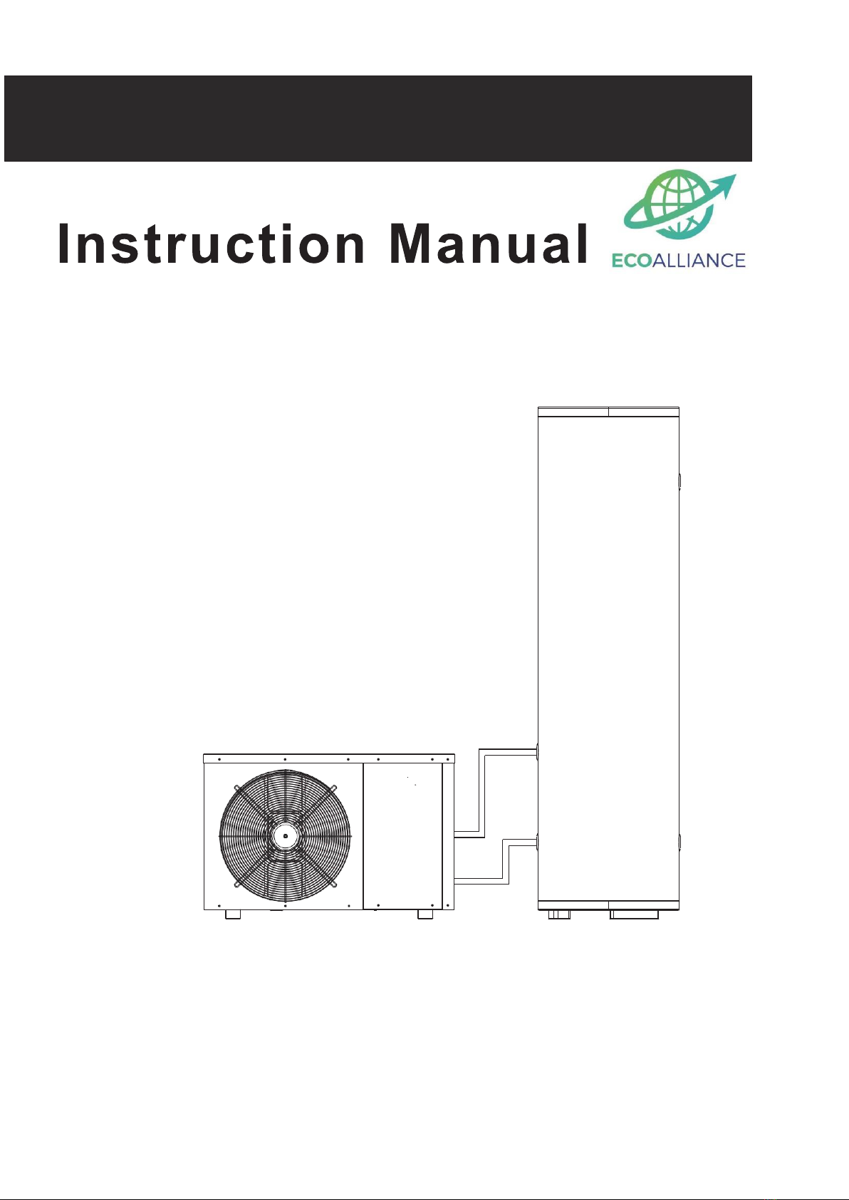
This manual suits for next models
7
Table of contents
Other ECOALLIANCE Water Heater manuals
Popular Water Heater manuals by other brands

Giant
Giant PV1 Owner's manual installation and operating instructions

IBC
IBC 30 Installation and operating instructions

Quantum
Quantum 270-11AC3-134 owner's manual

Danfoss
Danfoss Termix Novi 1 Series installation guide

onsen
onsen 10L operating manual

Ariston
Ariston VELIS TECH PW ABSE 80 Assembly and operation instructions

Flexiheat
Flexiheat S Series Installation, operation and maintenance manual

A.O. Smith
A.O. Smith 505 Operation & installation manual

State Water Heaters
State Water Heaters GPG/GPV-540A Replacement parts list

Koncar
Koncar EGV10P2R instruction manual

clage
clage Zip 27941 installation instructions

Midea
Midea MWH-35MPC Operation manual