Ecoer R-410A User manual

1/62
ESI (Ultra) Service Manual www.ecoer.com
03.2021Manufacturer reserves the right to change specifications or designs without notice.
ESI (Ultra) R-410A
Unitary Service Manual
Contents
1. General Information----------------------------
2. ESI (Ultra) Unitary System---------------------
2.1 Refrigerant Circuit----------------------------
2.2 Function and Control------------------------
2.3 Field Setting-----------------------------------
3. Troubleshooting----------------------------------
3.1 Problems without Codes --------------------
3.2 Error Codes list ----------------------------- -
4. Parts List--------------------------------------------
5. Appendix-------------------------------------------
5.1 Sensor Characteristics------------------------
5.2 Wiring Diagram-------------------------------
2
3
3
7
17
27
27
29
56
58
58
62
All phases of this installation must comply with National, State and Local Codes.
IMPORTANT
These instructions do not cover all variations in systems or provide for every possible contingency to
be met in connection with installing and servicing. Should further information be desired or should
particular problems arise which are not covered sufficiently for the purchaser’s purposes, the matter
should be referred to local distributor.
2/62
ESI (Ultra) Service Manual www.ecoer.com
03.2021Manufacturer reserves the right to change specifications or designs without notice.
1 General Information
E OD A 18 H - 4860
1 2 3 4 5 6
Brand
E: Ecoer
Product Series
OD: Outdoor Condensing Unit
Model Letters
A: 208/230V-1Ph-60Hz
SEER
18: 18SEER Series
Type
H: Heat Pump C: AC only
Capacity
2436: up to 3Ton 4860: up to 5Ton
Condensing
Unit
E AH A T N - 36
1 2 3 4 5 6
Brand
E: Ecoer
Product Series
AH: Indoor Air Handler
Model Letters
A: 208/230V-1Ph-60Hz
Metering device
T: TXV
Communications
N: 24V Normal
Capacity
24=2Ton 36=3Ton 48=4Ton 60=5Ton
E series
Air Handler
3/62
ESI (Ultra) Service Manual www.ecoer.com
03.2021Manufacturer reserves the right to change specifications or designs without notice.
2.1 Refrigerant Circuit
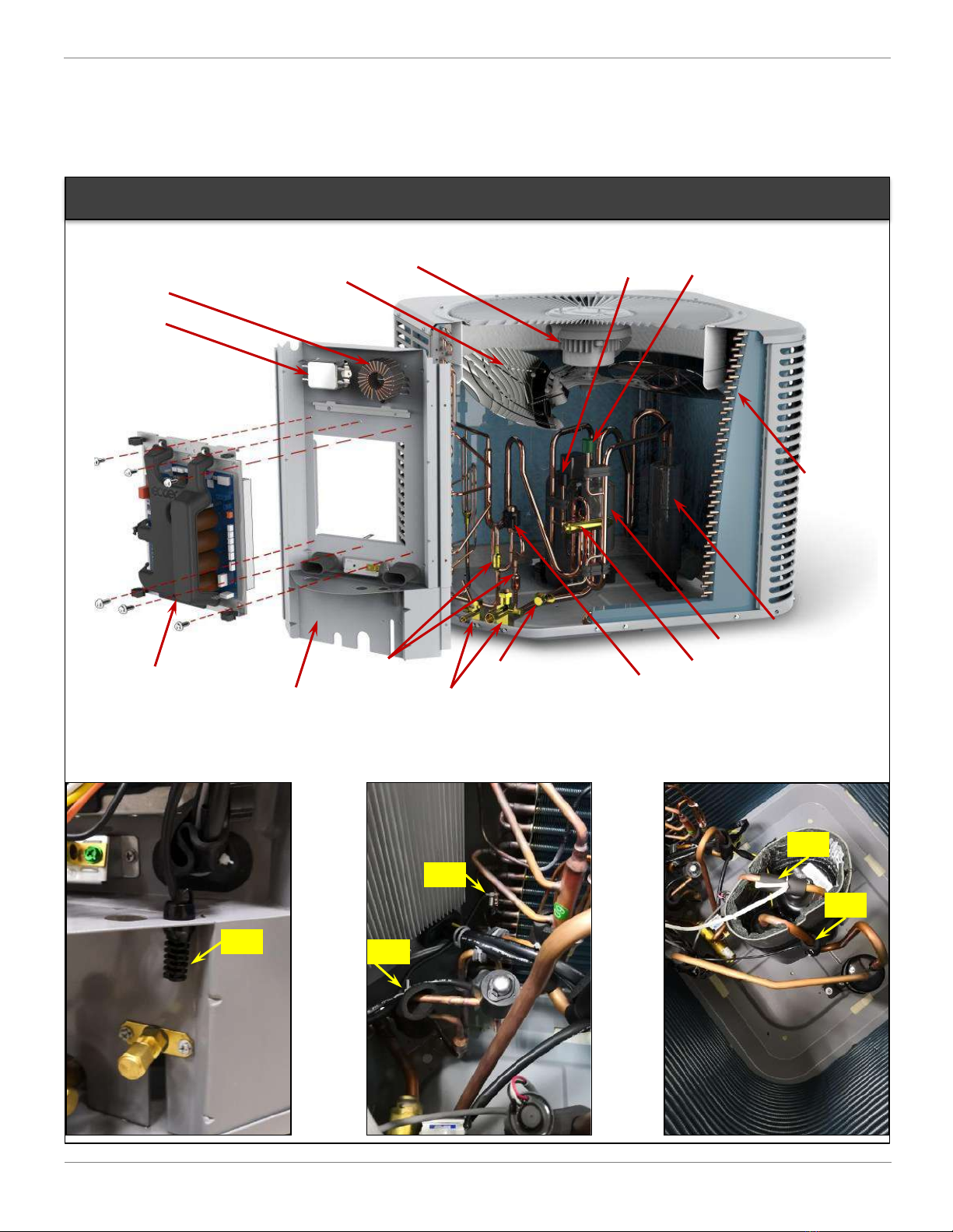
2.1.1 Functional Parts Layout of Condensing Units
2 ESI (Ultra) Unitary System
TH
TL
TS
TD
TA
DC Motor (FAN)
Main Control Board (PCB)
Accumulator (ACC)
Noise Filter
Inductance Fan Blades
Heat
Exchanger
Liquid / Gas Service Valve
Inverter Compressor (INV)
Reversing Valve (ST1)
Electronic Expansion
Valve (EEV)
Strainers Gauge Port
High Pressure
Sensor (HP) Low Pressure
Sensor (LP)
Lower Side Plate
EODA18H-2436

4/62
ESI (Ultra) Service Manual www.ecoer.com
03.2021Manufacturer reserves the right to change specifications or designs without notice.
TS
TD
TA
TA
DC Motor (FAN)
Main Control Board (PCB)
Accumulator (ACC)
Noise Filter
Inductance
Fan Blades Heat
Exchanger
Liquid / Gas Service Valve Inverter Compressor (INV)
Reversing Valve (ST1)
Electronic Expansion
Valve (EEV)
Strainers Gauge Port
High Pressure
Sensor (HP) Low Pressure
Sensor (LP)
Lower Side Plate
TIPS:
Remove screws to take away the lower
side plate to access TH / TL sensors.
A slotted screwdriver may be required to
open the plate from the condensing unit.
TH
TL
EODA18H-4860

5/62
ESI (Ultra) Service Manual www.ecoer.com
03.2021Manufacturer reserves the right to change specifications or designs without notice.
2.1.2 Major Components Functions and Refrigerant Circuits Diagram
HP TD
EEV
INV
TH
TA
ST1
(RV)
TS
TL
ACC
Liquid Service Valve
Heat Exchanger
Gas Service Valve
Gauge Port
FAN
LP
Name
Symbol
Function
Inverter compressor
INV Adjusts refrigerant flow rate by changing the compressor speed (RPS)
based on objective pressure.
DC motor FAN Outputs heat exchanger capacity by adjusting the motor rotation speed
based on operating pressure.
Electronic expansion
valve EEV 1) Fully open in cooling mode and defrost operation.
2) Control compressor discharge superheat in heating mode.
Reversing valve ST1
(RV)
Switches the operation mode between heating and cooling (including
defrost control).
Temperature sensor
TA Uses to detect outdoor air temperature and control fan speed.
TS Uses to detect compressor suction temperature and calculate compressor
suction superheat (SH).
TD Uses to detect compressor discharge temperature and calculate
compressor discharge superheat (DSH).
TH Uses to control defrosting during heating operation.
TL Uses to detect liquid line temperature and calculate sub-cooling (SC).
TF Uses to detect heat sink temperature of inverter module.
High pressure sensor
HP Uses to detect high pressure.
Low pressure sensor
LP Uses to detect low pressure.
Accumulator ACC Uses to store excess refrigerant.

6/62
ESI (Ultra) Service Manual www.ecoer.com
03.2021Manufacturer reserves the right to change specifications or designs without notice.
2.1.3 Refrigerant Flow of Each Operation Mode
Cooling Operation (including defrost operation and cooling oil return)
HP
TD
EEV
INV
TH
TA
ST1
(RV)
TS
TL
ACC
Liquid Service Valve
Heat Exchanger
Gas Service Valve
Gauge Port
TXV
Indoor Coil
High pressure Gas
High pressure Liquid
Low pressure Gas
Low pressure Mix.
FAN
LP
Strainer
Heating Operation (including heating oil return)
HP
TD
EEV
INV
TH
TA
ST1
(RV)
TS
TL
ACC
Liquid Service Valve
Heat Exchanger
Gas Service Valve
Gauge Port
TXV
Indoor Coil
High pressure Gas
High pressure Liquid
Low pressure Gas
Low pressure Mix.
FAN
LP
Strainer

7/62
ESI (Ultra) Service Manual www.ecoer.com
03.2021Manufacturer reserves the right to change specifications or designs without notice.
2.2 Function and Control
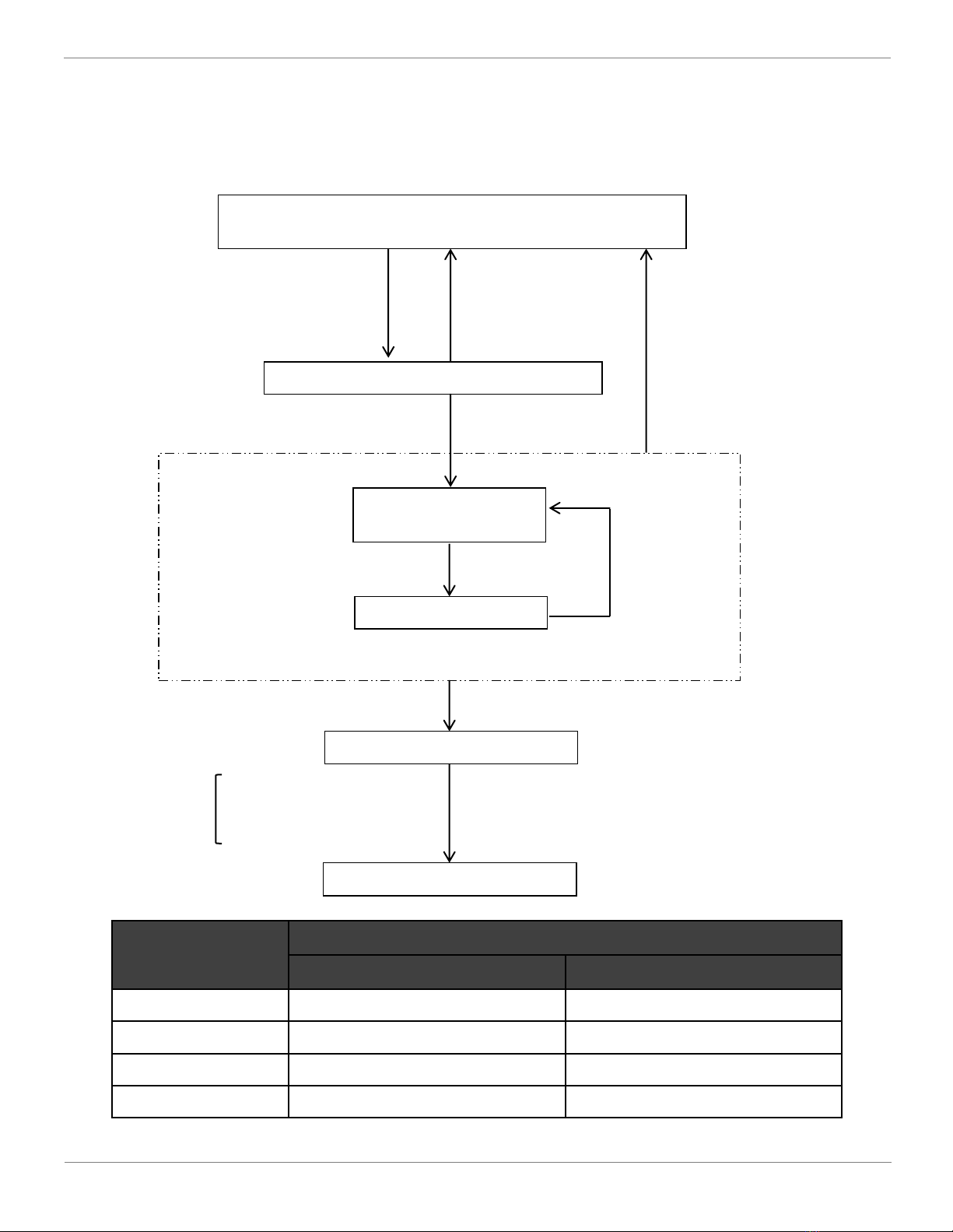
2.2.1 Operation Mode
NOTES: The operation may be enforced to complete under some conditions.
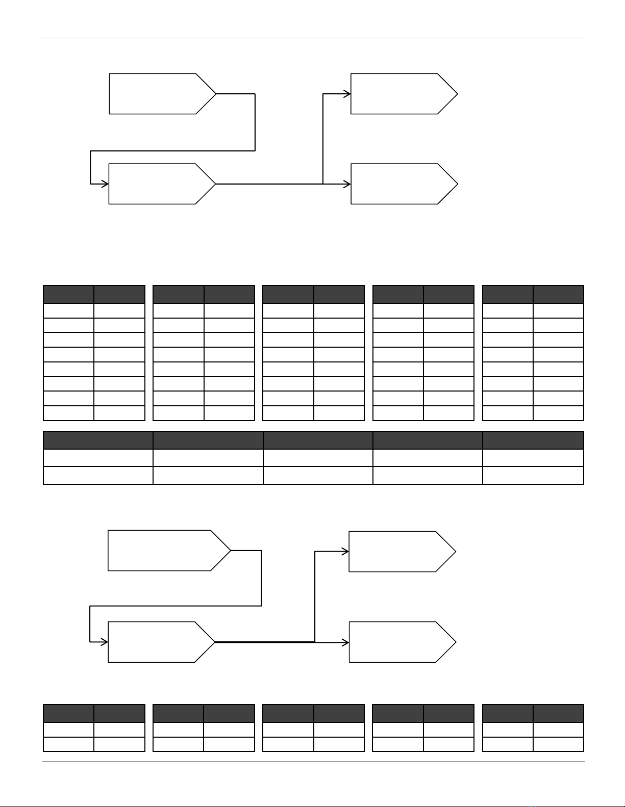
Operation in stop mode
Pressure equalizing
prior to start-up
Thermostat ON (Y energized)
•Thermostat OFF
(Y de-energized)
•O signal change
Start-up control *NOTE
・Cooling start-up
(O energized)
・Heating start-up
(O de-energized)
Cooling or heating
operation
Oil return IN
conditions are met.
Defrost IN
conditions are met.
NO
NO
Oil return operation *NOTE
YES
Defrost operation *NOTE
YES
Normal operation
•Compressor PI control
•EEV PI control
•Fan motor control
•Protection control
Restart standby
(compressor stops)
Malfunction
MAX. 6 minutes
After 1 minute

8/62
ESI (Ultra) Service Manual www.ecoer.com
03.2021Manufacturer reserves the right to change specifications or designs without notice.
2.2.2 Basic control
2.2.2.1 Normal control
Input
Signal
Actuator
Cooling control
(including
cooling oil return)
Heating control
(including
heating oil return)
YCompressor (INV) Apply PI control to maintain Tes*1 Apply PI control to maintain Tcs*1
Y / O*2 Outdoor fan (FAN) Cooling fan control Heating fan control
O*2 Reversing valve (ST1) De-energized Energized (208/230VAC)
Y / O*2 Electronic expansion
valve (EEV) 480pls PI control to maintain discharge
superheat (DSH)
Remarks:
1. Tes: Target Te value (Varies depending on the load of space, mode choice, silent setting, etc.)
Te: Low pressure equivalent saturation temperature
Tcs: Target Tc value (Varies depending on the load of space, mode choice, silent setting, etc.)
Tc: High pressure equivalent saturation temperature
2. SW1_3=OFF (factory), condensing unit uses Y/C/O (O for cooling) signal to operate heat pump.
SW1_3=ON has been set, condensing unit uses Y/C signal to run cooling only.
2.2.2.2 Defrost control
This system carries out demand defrost control if any one of the following conditions satisfy.
I. The calculated temperature difference between ambient temperature (TA) and defrost
temperature (TH) is called Delta T. After Delta T is achieved and continues for 5 minutes.
II. After “Minimum Run Time” (MRT) is achieved.
III. The high pressure drops below 245psi for 20 minutes if TA is between 14°Fand 28°F.
IV. Manual defrosting can be chosen from n08 setting.
Defrost will be terminated once defrost temperature sensor (TH) reaches 64°F for one (1) minute or
the defrost time has exceeded eight (8) minutes. Defrost mode setting (n04) offers termination
options for different geographical conditions.
a) TA is between 41°F and 59 °F: TH ≤ 30°F, Delta T = 18°F
b) TA is between 19°F and 41°F: TH ≤ 30°F, Delta T = 12~18°F
c) TA is less than 19°F: TH < 9°F, accumulative compressor run time ≥ 80 minutes
TH back-up running: TA < 59°F and LP ≤ 90psi, accumulative compressor run time ≥ 60 minutes
a) MRT is 3.5 hours if TA is less than 23°F
b) MRT is 2 hours if TA is between 23°F and 43°F
Start-up control is enforced to complete, then wait another 5 minutes to activate the defrost operation.
a) Defrost in heavy snow area will extend defrost for one (1) minute, but reduce the heating time to
execute more defrost cycles.
b) Defrost in light snow area will reduce defrost for 30 seconds.
1 2 3 4
ON DIP
SW1 on ODU PCB
SW1_3: AC / HP
Switch
9/62
ESI (Ultra) Service Manual www.ecoer.com
03.2021Manufacturer reserves the right to change specifications or designs without notice.
2.2.2.3AUTO charge mode and pump down function
Actuator
AUTO charge mode OR
Pump down
in cooling
Pump down in heating
Compressor (INV)
2ton: 56rps→26rps
3ton: 66rps→36rps
4ton: 56rps→26rps
5ton: 66rps→36rps
2ton: 66rps→26rps
3ton: 80rps→36rps
4ton: 58rps→26rps
5ton: 70rps→36rps
Outdoor fan (FAN) Cooling fan control Heating fan control
Reversing valve (ST1) De-energized Energized (208/230Vac)
Electronic expansion valve (EEV) 480pls PI control to maintain DSH
AUTO charge mode locks the compressor speed in cooling. The LED will display the refrigerant
coefficient if both the liquid line sub-cooling (SC) and compressor suction superheat (SH) of ESI
system are proper. To keep the best Ecoer Smart Inverter (ESI) systems’ performance and reliability,
the following requirements should be followed in cooling.
•If the LED displays “--”in AUTO charge mode for more than 20 minutes, stop charging and use a
wrench to clockwise the TXV to ensure SH is no less than 7゜F.
•In case that the cooling performance is terrible due to improper superheat (i.e. SH >20゜F). Adjust
the system according to
1. Activate AUTO charge mode to fix compressor frequency (RPS) by press BS4 for 5 seconds on
outdoor PCB. Run the system for 15~20 minutes and check refrigerant coefficient number
from LED display or ESS Pro App, add refrigerant unless the coefficient number is less
than 0.6.
2. Open the front panel of the indoor unit, use a wrench to counterclockwise the TXV until SH
≤20゜F. This will make more refrigerant flow into indoor coil for better cooling performance.
Pump down locks the compressor speed depending on the
actual mode. On the thermostat, set coolingfor refrigerant recovery
to condenser or heating for refrigerant migration to indoor coil and
line sets. Hold and press BS4 button for 5 seconds until you see
blinking ‘7’, press BS2 button in one minute to get ‘8’.
Once pump down is activated. The low pressure will be displayed on
LED. *NOTE Low pressure protection is valid if LP <24.5psig.
SEG1 SEG2 SEG3
SEG1 SEG2 SEG3
SC
6~18゜FTarget SC and SH
in cooling SH
7~20゜F
BS1 BS2 BS3
BS4
10/62
ESI (Ultra) Service Manual www.ecoer.com
03.2021Manufacturer reserves the right to change specifications or designs without notice.
2.2.2.5 Fan control
[Fan RPM VS STEP]
STEP RPM STEP RPM STEP RPM STEP RPM STEP RPM
0 0 2 450 4680 6830 8930
1350 3550 5780 7880 9980
2.2.2.4 Compressor control
[Compressor RPS VS STEP]
STEP RPS STEP RPS STEP RPS STEP RPS STEP RPS
1 - 9 28 17 44 25 60 33 76
2 - 10 30 18 46 26 62 34 78
316 11 32 19 48 27 64 35 80
418 12 34 20 50 28 66 36 82
520 13 36 21 52 29 68 37 84
622 14 38 22 54 30 70 38 86
724 15 40 23 56 31 72 39 88
826 16 42 24 58 32 74 40 90
Outdoor Capacity
2Ton 3Ton 4Ton 5Ton
Cooling Max RPS 70 80 66 76
Heating Max RPS 80 90 80 90
Start-up control
PI control
Directive control
•Pressure differential control
•MAX time (cooling) ≤ 10 minutes
•MAX time (heating) ≤ 45 minutes
Fixed speed
Depending on the load of the space.
Standby
MAX 6 minutes for pressure
equalization
Start-up control
Pressure control
Directive control
Standby after
getting start signal
MAX STEP •Cooling fan control by high pressure
•Heating fan control by low pressure
Fixed speed

11/62
ESI (Ultra) Service Manual www.ecoer.com
03.2021Manufacturer reserves the right to change specifications or designs without notice.
2.2.2.6 Electronic expansion valve (EEV) control
NOTE: Heating DSH should be between 25 ゜F and 50 ゜F with proper refrigerant level.
•Overcharged: DSH is less than 18 ゜F with EEV opening < 72pls.
•Undercharged: DSH is higher than 50 ゜F with EEV opening ≥ 460pls
2.2.2.7 Silent mode
In order to decrease the noises produced by condensing unit, the crucial noise resources should be
limited. Once the silent mode has been activated by n05, n06 and n07 (refer to field setting), both the
highest compressor frequency (RPS) and fan speed (RPM) are limited.
Max Fan Speed (RPM)
Condenser Capacity Standard Mode Silent Mode (Level 1) Super Silent Mode (Level 2)
2Ton 830 680 550
3Ton 930
Cooling: 830
Heating: 780
680
4Ton 880 830 780
5Ton 980 880 780
Cooling Max Compressor RPS
Condenser Capacity Standard Mode Silent Mode (Level 1) Super Silent Mode (Level 2)
2Ton 70 66 56
3Ton 80 76 70
4Ton 66 66 56
5Ton 76 68 58
Maximum compressor frequency
Maximum fan speed
Heating Max Compressor RPS
Condenser Capacity Standard Mode Silent Mode (Level 1) Super Silent Mode (Level 2)
2Ton 80 70 60
3Ton 90 78 72
4Ton 80 62 52
5Ton 90 70 60
Start-up control
PI control
Directive control
•Cooling: 480pls
•Heating: Temperature differential control
Fixed opening
Standby after
getting start signal
•Cooling: 360pls→480pls
•Heating: 360pls→0pls •Cooling: 480pls
•Heating: Depending on the compressor
discharge superheat (DSH). *NOTE
DSH
25~50゜F
12/62
ESI (Ultra) Service Manual www.ecoer.com
03.2021Manufacturer reserves the right to change specifications or designs without notice.
2.2.3. Protection controls
HP≥C
Normal operation
(Upper limit compressor step = Max. step)
HP<D
Upper limit compressor
step: Decrease 2step
Current step maintained
After 15 sec.
HP≥A
High pressure abnormal standby
HP≥B
Upper limit compressor step = Current step
HP≥B
Compressor restarts
HP<D
Symbol
EODA18H-2436/4860
Cooling Heating
A545psig [3.8MPa] 545psig [3.8MPa]
B493psig [3.4MPa] 479psig [3.3MPa]
C479psig [3.3MPa] 450psig [3.1MPa]
D464psig [3.2MPa] 421psig [2.9MPa]
2.2.3.1 High pressure protection control
High pressure (HP) protection control is used to prevent extremely high pressures in the system and
protect the compressor.
Restart permission=ON
and
HP<D

13/62
ESI (Ultra) Service Manual www.ecoer.com
03.2021Manufacturer reserves the right to change specifications or designs without notice.
LP<C
Normal operation
(Upper limit compressor step = Max. step)
LP≥D
Upper limit compressor
step: Decrease 2steps
Current step maintained
After 15 sec.
LP<A
Low pressure abnormal standby
LP<B
Upper limit compressor step = Current step
LP<B
Compressor restarts
LP≥D
Symbol EODA18H-2436/4860
A 24.5psig [0.17MPa]
B 43.5psig [0.30MPa]
C 61.0psig [0.42MPa]
D 72.5psig [0.50MPa]
2.2.3.2 Low pressure protection control in cooling mode
Low pressure (LP) protection control in cooling is used to protect compressor against the transient
decrease of low pressure.
Restart permission=ON
and
LP≥D

14/62
ESI (Ultra) Service Manual www.ecoer.com
03.2021Manufacturer reserves the right to change specifications or designs without notice.
2.2.3.3 Discharge temperature protection control
This discharge temperature (TD) protection control is used to protect the compressor internal
temperature against a malfunction or transient increase of discharge pipe temperature.
TD≥C
Normal operation
(Upper limit compressor step = Max. step)
TD<D
Upper limit compressor
step: Decrease 2steps
Current step maintained
After 15 sec.
TD≥A
Discharge temperature abnormal standby
TD≥B
Upper limit compressor step = Current step
TD≥B
Compressor restarts
TD<D
Symbol
EODA18H-2436/4860
Cooling Heating
A248°F (120°C) 230°F (110°C)
B230°F (110°C) 212°F (100°C)
C212°F (100°C) 194°F (90°C)
D194°F (90°C) 176°F (80°C)
Restart permission=ON
and
TD<D

15/62
ESI (Ultra) Service Manual www.ecoer.com
03.2021Manufacturer reserves the right to change specifications or designs without notice.
2.2.3.4 INV Module temperature protection control
Inverter module temperature (TF) protection control is performed to prevent tripping due to an
abnormal increase in temperature.
TF≥C
Normal operation
(Upper limit compressor step = Max. step)
TF<D
Upper limit compressor
step: Decrease 1step
Current step maintained
After 15 sec.
TF≥A
Inverter heat sink temperature abnormal standby
TF≥B
Upper limit compressor step = Current step
TF≥B
Compressor restarts
TF<D
Symbol
EODA18H-2436 EODA18H-4860
Cooling Heating Cooling Heating
A181°F (83°C) 181°F (83°C) 176°F (80°C) 167°F (75°C)
B174°F (79°C) 158°F (70°C) 158°F (70°C) 149°F (65°C)
C167°F (75°C) 153°F (67°C) 151°F (66°C) 142°F (61°C)
D162°F (72°C) 147°F (64°C) 145°F (63°C) 136°F (58°C)
Restart permission=ON
and
TF<D
16/62
ESI (Ultra) Service Manual www.ecoer.com
03.2021Manufacturer reserves the right to change specifications or designs without notice.
2.2.3.5 Compressor over-current protection control
This control is performed to prevent tripping due to an abnormal transient compressor current (IA).
IA≥C
Normal operation
(Upper limit compressor step = Max. step)
IA<D
Upper limit compressor
step: Decrease 1step
Current step maintained
After 30 sec.
IA≥A
Inverter current abnormal standby
IA≥B
Upper limit compressor step = Current step
IA≥B
Compressor restarts
IA<D
Symbol
EODA18H-2436 EODA18H-4860
Cooling Heating Cooling Heating
A16A 16A 20A 20A
B 9.2A 9.5A 12.1A 12.1A
C 8.6A 9.1A 11.7A 11.7A
D 8.0A 8.5A 11.2A 11.2A
Restart permission=ON
and
IA<D
17/62
ESI (Ultra) Service Manual www.ecoer.com
03.2021Manufacturer reserves the right to change specifications or designs without notice.
LED on main control board can display the operating status of outdoor unit (ODU).
2.3 Field Setting
2.3.1 Default display
SEG1: Normally blank, but it displays codes “0to 9”accordingly if there is damaged sensor and
command response.
SEG2: Normally blank, but it will display code accordingly as below if outdoor unit is running under
limited condition.
SEG3: It displays outdoor unit’s operation mode.
SEG1 Code
Description Time
0 Software is updating through IoT device About 5 min.
1 High pressure sensor (HP) fault back-up running 7 Days
2 Low pressure sensor (LP) fault back-up running 7 Days
3 Compressor discharge temperature sensor (TD) fault back-up running 7 Days
4 IPM module temperature sensor (TF) fault back-up running 7 Days
5 Ambient temperature sensor (TA) fault back-up running 120 Days
6 Defrost sensor (TH) fault back-up running 90 Days
7 Compressor suction temperature sensor (TS) fault back-up running 120 Days
8 Liquid line temperature sensor (TL) fault back-up running 120 Days
9 IoT command response -
SEG2 Code Description
0 Running under high pressure (HP) limit
1 Running under low pressure (LP) limit
2 Running under discharge temperature (TD) limit
3 Running under IPM module temperature (TF) limit
4 Running under compressor current limit
SEG3 Code Description
0 Stop (Y signal de-energized)
1 Ready to start-up (Y signal energized) *Note
2 Cooling
3 Heating
4 Oil return
5 Defrost
6 Manual defrost
7 AUTO charge mode in cooling
8 Pump down
Note: Compressor waits three to eight minutes to restart.
7 segment display instructions
SEG1 SEG2 SEG3

18/62
ESI (Ultra) Service Manual www.ecoer.com
03.2021Manufacturer reserves the right to change specifications or designs without notice.
Modes list (SEG3 Display)
SEG1 SEG2 SEG3
Stop or standby (Y signal de-energized)
SEG1 SEG2 SEG3
Ready to start-up (Y signal energized)
(6 to 8 minutes for pressure equalization to restart)
SEG1 SEG2 SEG3
Cooling
SEG1 SEG2 SEG3
Heating
SEG1 SEG2 SEG3
Oil return
SEG1 SEG2 SEG3
Defrost
SEG1 SEG2 SEG3
Manual defrost
SEG1 SEG2 SEG3
AUTO charge mode in cooling
SEG1 SEG2 SEG3
Pump down
19/62
ESI (Ultra) Service Manual www.ecoer.com
03.2021Manufacturer reserves the right to change specifications or designs without notice.
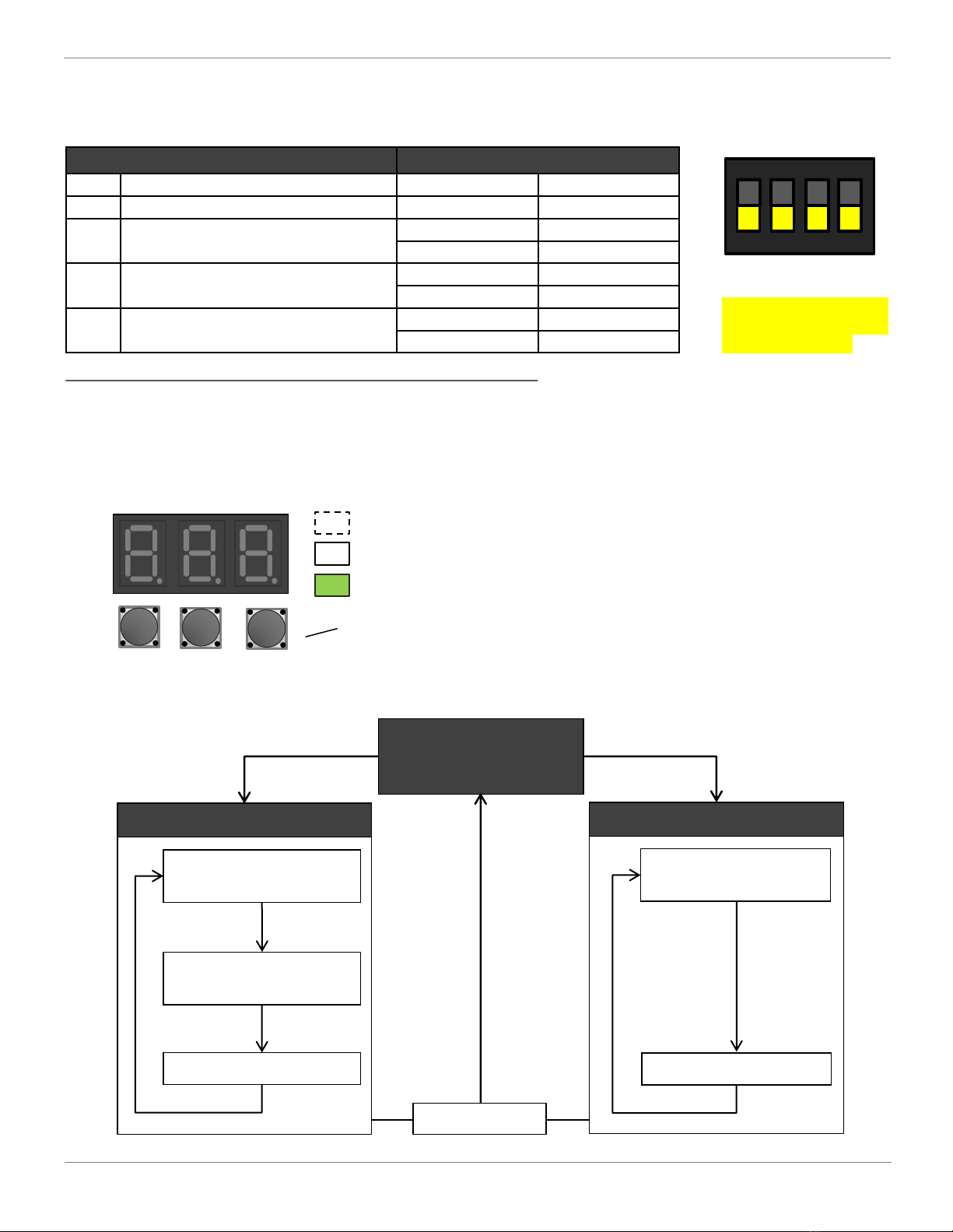
2.3.2 Setting by dip switches
2.3.3 Setting by pressing buttons
Query and setting operations can be done by pressing buttons on main control board.
SW1 dip switch Description
NO.Setting item Status Content
1Reserved - -
2Capacity selection ON 2 or 4 Ton
OFF (factory) 3 or 5 Ton
3AC only/Heat pump selection ON AC only
OFF (factory) Heat pump
4Command *response for IoT ON No
OFF (factory) Yes
* Remote field setting, troubleshooting, software updates and so on.
Condensing units’ functions can be applied by dipping switch and pressing buttons.
1 2 3 4
ON DIP
SW1
Use minor straight
screwdriver to dip switch.
Must power off the unit
for at least 2 minutes to
activate the change.
BS1
BS1: Menu or back button
BS2: UP button
BS3: Spot check and confirm button
Remarks: Press or tip any directions are valid.
BS2 BS3
Press buttons
Off
Blinking
On
SEG1 SEG2 SEG3
Setting mode
Default mode
(Press BS3 button to
spot check running data)
Press and hold BS1for 5 seconds
to set special functions.
Press BS3
Symbol selection by
pressing BS2 button
Setting item selection
by pressing BS2 button
Contents display
Press BS3
Press BS3
Query settings
Press BS3
Symbol selection by
pressing BS2 button
Contents display
Press BS3
Press BS1 once to query
current setting.
Press BS1 once

20/62
ESI (Ultra) Service Manual www.ecoer.com
03.2021Manufacturer reserves the right to change specifications or designs without notice.
System states can be showed on the 7 segments display (LED) of outdoor unit. Press BS3button to get
code number and corresponding detailed information with an interval of one second.
Example:
Code number Detailed information
Remark:
When multi-error codes exist at the same time, each code will be displayed one by one with an interval of one second.
SEG1 SEG2 SEG3 SEG1 SEG2 SEG3
Default mode (Spot check)
No. Number content Example Description
Default Refer to default display instructions 902
9: Command
0: Running under high pressure limit
2: Cooling mode
01-Outdoor unit type and capacity H3 H: heat pump C: AC only
3: 3Ton
02-Liquid line sub-cooling 10 10°F
03-Compressor suction superheat 18 18°F
04-Compressor speed 56 56RPS
05-Electronic expansion valve opening 360 360pls
06-Step of fan 8 The 8th step
07-Low pressure (LP sensor) 145 145psig
08-High pressure (HP sensor) 350 350psig
09-Outdoor ambient temp. (TA) 95 95°F
10-Compressor suction temp. (TS) 70 70°F
11-Compressor discharge temp. (TD) 170 170°F
12-Defrost sensor temp. (TH) 80 80°F
13-Liquid line temp. (TL) 70 70°F
14-Inverter module temp. (TF) 150 150°F
15-Target evaporating temp. (Tes) 43 43°F
16-Current evaporating temp. (Te)45 45°F
17-Target condensing temp. (Tcs)104 104°F
18-Current condensing temp. (Tc) 112 112°F
19-Compressor DC current 10.1 10.1A
20-Undercharged refrigerant signal 1 0: None 1: Level 1 2: Level 2 (severe)
21-Main software version A01 A01 version
22-Inverter software version b01 b01 version
23-Current fault E1 Display up to 5 *codes
24-The last fault F1 --: None
25-Fault before the last fault F2 --: None
Table of contents
Other Ecoer Heat Pump manuals


Popular Heat Pump manuals by other brands


Metro Therm
Metro Therm METROAIR I 8 Installer manual

POOLEX
POOLEX Nano Action Reversible Installation and user manual

York
York B1HH018 installation instructions

MICROWELL
MICROWELL HP 1000 GREEN Installation and user manual

Nortek
Nortek Q5RD Series installation instructions

Panasonic
Panasonic WH-MDC05H3E5 Service manual


