ECOHOT WHO_321064-NG User manual

Installation Manual and Owner’s Guide WHO-321064-NG, WHO-321064-LP
ECOHOT TM
1 of 27
ECOHOT TM
Installation Manual and Owners Guide
Model no. WHO_321064-NG, WHO_321064-LP Instantaneous Water Heater
For Exterior Use Only
ATTENTION: Prior To Installation, You Must Check Sizing Of Gas Pipe Line
For Proper BTU's. See page 8 For Sizing Chart.
(Be Sure To Calculate Total BTU's of all Appliances On Gas Line)
Please read this manual carefully
Domestic Hot Water Use in CommercialApplications Will Limit Warranty
Do not store or use gasoline or other flammable vapors and liquids in the vicinity of this or
any other appliance.
WHAT TO DO IF YOU SMELL GAS
Do not try to light any appliance.
Do not touch any electrical switch; do not use any phone in your building.
Immediately call your gas supplier from a neighbor’s phone. Follow the gas supplier’s
instructions.
If you cannot reach your gas supplier, call the fire department.
Installation and service must be performed by a qualified installer, service agency or the
gas supplier.
WARNING: IFTHE INFORMATION IN THESE INSTRUCTIONS IS
NOT FOLLOWED EXACTLY,AFIRE OR EXPLOSION MAY RESULT,
CAUSING PROPERTY DAMAGE, PERSONAL INJURY OR DEATH.
******* IMPORTANT************
Upon completion of the installation, these instructions should be handed to the user of the appliance for
future reference.
In the commonwealth of Massachusetts this product must be installed by a licensed plumber.
This product is not approved for manufactured homes (mobile home), recreational vehicles (RV)
or boats.

Installation Manual and Owner’s Guide WHO-321064-NG, WHO-321064-LP
ECOHOT TM
2 of 27
TABLE OF CONTENTS
FEATURES:...............................................................................................................................................................3
SPECIFICATIONS: ..................................................................................................................................................3
INSTALLATION INSTRUCTIONS:.......................................................................................................................3
Finding the Proper Location
Mounting
Installation of Gas Line
Installation of Cold Water Supply
Installation of Hot Water Outlet
Installation of Power Supply
GENERALRULES TO FOLLOW FOR SAFE OPERATION.............................................................................5
Anti Freeze Device.....................................................................................................................................................6
Gas Supply..................................................................................................................................................................6
Gas Piping, Connections and Gas Regulator
Gas Line Sizing (Natual Gas and LPGas)
High Altitude Operation
Water Connections.....................................................................................................................................................9
TURNINGTHE WATER HEATER ON
TURNINGTHE WATER HEATER OFF
Connecting the pressure relief valve (PRV)
OPERATING INSTRUCTIONS ............................................................................................................................11
WHAT TO DO IFYOU SMELLGAS
MAINTENANCEAND SERVICE.........................................................................................................................12
TROUBLE SHOOTING.........................................................................................................................................16
Introduction
No spark at the pilot
Flow
Error Code
PARTS LIST.............................................................................................................................................................20
Figure 1: Interior Diagram .....................................................................................................................................22
Figure 2: Plumbing Installation..............................................................................................................................23
Figure 3: Front & Side Views..................................................................................................................................23
Figure 4: Direct Vent Terminal...............................................................................................................................24
Figure 5: Wiring Diagram……………………………….......................................................................................26
Figure 6: Tankless Water Heater with Domestic Recirculation Loop.................................................................27

Installation Manual and Owner’s Guide WHO-321064-NG, WHO-321064-LP
ECOHOT TM
3 of 27
Note:
Specifications are subject to change without prior notice.
FEATURES:
●Freeze protection device 5F(-15C);
●Constant temperature control;
●Copper heating coils for endless supply of hot water;
●Self diagnostic function with malfunction number display on remote control.
●Automatic overheating protection shut-off sensor;
●Stainless steel burners with stabilized blue flame;
●Compact space saver: mounts on a wall with 4 screws;
●Easily removable one-piece cover;
●Easy one person installation;
●Red LED indicator display F &C water temperatures on remote controller;
ECOHOTTM WHO-321064-LP, WHO-321064-NG
SPECIFICATIONS:
●Gas input max: 218,000 Btu/hr
●Min: 18,000 Btu/hr
●Water Connection 3/4”Thread fitting NPT
●Box Size: H x W x D=31” x 18” x 11”
●Actual Size: H x W x D=24” x 15” x 8”
●Gas Connection 3/4” NPT thread
●Net Weight 44 lbs, Shipping Weight 50 lbs.
●5.8 GPM (21 L) at 65°rise
●8.4 GPM (31 L) at 45°rise
●Maximum Working Water Presser 150PSI (1.035 MPa)
●.8 GPM Flow Rate toActivate ECOHOTTM Water Heater.
Temp Rise Above
Ground Water
30
°F
40
°F
50
°F
60
°F
70
°F
80
°F
Flow Rate (Gal/Min.)
12.5
9.4
7.5
6.3
5.4
4.7
Temp Rise Above
Ground Water
90
°F
100
°F
110
°F
120
°F
130
°F
Flow Rate (Gal/Min.)
4.2
3.8
3.4
3.1
2.9
Note: Specifications are subject to change without prior notice. Local and State codes
must be adhered to prior to installation.

Installation Manual and Owner’s Guide WHO-321064-NG, WHO-321064-LP
ECOHOT TM
4 of 27
INSTALLATION INSTRUCTIONS:
MUST READ PRIOR TO INSTALLATION
Always wear safety glasses and gloves
Must be mounted a min. of 12” above the floor
Finding the Proper Location:
1. Make sure you install your tank-less water heater in an area that exhaust has 4ft or more
from any window or door (check local codes). Exhaust vent must be a min. of 7ft. above
public walk ways or paved drive ways. Minimum 3 feet below eaves or gutters. See Fig 4.
2. Do not install in home or enclosed area.
DANGER
Vapors from flammable liquids will explode and catch fire causing death or severe burns.
Do not use or store flammable products such as gasoline, solvents or adhesives near the water heater.
Mounting:
1. Use stud finder or other common method to find wall studs or wood under stucco. Mount
water heater with a minimum of 2 ½” non-corrosive wood screws. See Fig 3
2. Use four (4) 1” wood screws for wood siding or molly type screws to mount water heater to
stucco or concrete. (Note Use corrosion resistant screws)
Installation of Gas Line:
1. Ensure that your gas supply is properly sized, check with your local gas company and gas
chart in this manual.
2. Install a gas shut off valve on the gas supply line. (See Fig. 2)
3. Be sure to install a sediment trap and a union connection. (See Fig. 2).
4. Make sure to check the name plate for the correct gas type supply NG or LP.
Installation of Cold Water Supply:
The inlet line, cold water supply is on the right hand side (always use a min. of ¾” copper pipe, or
¾” flex line). Install shut off valve on water supply line. (See Figure 2)
Installation of Hot Water Outlet:
1. The outlet line, hot water supply is on the left hand side (always use a min. of ¾” copper
pipe or ¾” flex line). Install shut off valve on water supply line. ( See fig. 2)
2. Your hot water lines should be kept short to save water and energy, thus placement of this
appliance is important to save hot water costs. NOTE: Hot water lines should be
insulated. (Follow local codes).
3. When facing the heater the hot water outlet is on your left. Keep water inlet and outlet
pipes to no less than ¾” diameter to allow full flow capacity.

Installation Manual and Owner’s Guide WHO-321064-NG, WHO-321064-LP
ECOHOT TM
5 of 27
Remember:
1. Water pressure must be sufficient to activate the heater when drawing hot water from
the top floor.
2. If the hot and cold connections to the heater are reversed, the heater will not function.
3. 3/4’’Copper or brass fittings work best when connected to the connectors. (See Fig. 2)
4. The flexible type connectors (3/4” ID min.) will make instillation easier and seals to
the water valve by means of a union connection with a washer type gasket at the joint.
No pipe sealant or Teflon tape is to be used at this joint.
5. Be certain there are no loose particles or dirt in the piping. Blow out or flush the lines
before connecting to the ECOHOTTM. Full port valves should be installed on both the
cold water feed line and the hot water outlet line to facilitate servicing the heater.
6. For installation on a private well system, be sure that the water pressure is set
between 30 and 50 PSI. (See Fig. 2)
Installation of Power Supply
The ECOHOTTM water heater requires an electrical power supply from 120 VAC 60HZ circuit
and needs to be properly grounded.
TURNINGTHE WATER HEATER ON:
1. Open cold water supply valve, open hot water supply valve, and open hot water faucet
outlet to remove any air in the water lines.
2. Turn on gas valve.
3. Plug-in power supply.
4. Press the on/off button on remote to ON then set temperature (ECOHOTTM Recommends
120F/49C or less) and open water outlet in home. If a remote controller is provided,
adjust the temperature below 120F/49C (Default temperature), there is a hot water scald
potential if the remote controller is set too high. Should overheating occur or the gas supply
fail to shut of, turn off the manual gas control valve to the appliance. If water heater does
not get hot close and open outlet again to remove air from gas line, if this does not work
refer to trouble shooting.
TURNINGTHE WATER HEATER OFF:
1. Shut off hot water faucet.
2. Shut off gas valve.
Please Note:
CSC recommends that installers use large washers with the screws used to hang the heater. (See
Figure3)
Before installing the appliance, be certain you have the correct heater for your type of Gas-Propane
or Natural Gas. Identification labels are found on the shipping box, and on the rating plate, which
is located on the right side panel of the cover.

Installation Manual and Owner’s Guide WHO-321064-NG, WHO-321064-LP
ECOHOT TM
6 of 27
WARNING: California Proposition 65 lists chemical substances known to the state to cause
cancer, birth defects, death, serious illness or other reproductive harm. This product may contain
such substances, be their origin from fuel combustion (gas, oil) or components of the product itself.
GENERAL RULES TO FOLLOW FOR SAFE OPERATION
1. You should follow these instructions when you install your heater. In the Applianceed states:
The installation must conform with local codes or, in the absence of local codes, the National Fuel
Gas Code ANSI Z223. 1/NFPA54.
In Canada: The installation should conform to CSA B149. Natural Gas and Propane
Installation Code and /or local installation codes.
2. Placement of water heater is important. (Check your local building codes before installation).
If not installed correctly, fatal accidents can be caused.
3. The appliance must be electrically grounded in accordance with local codes or, in the absence of
local codes, with the National Electrical Code, ANSI/NFPA 70 and/or the CSA C22.1, Canadian
Electrical Code.
4. The appliance and its individual shutoff valve must be disconnected from the gas supply piping
system during any pressure testing at pressures in excess of 1/2 PSI (3.5Kpa)
5. The appliance must be isolated from the gas supply piping system by closing its individual
manual shut off valve during any pressure testing of the gas supply piping system at test pressures
equal to or less than 1/2 PSI (3.5Kpa).
6. The appliance and its gas connection must be leak tested with soapy water solution before
placing the appliance in operation.
7. Keep water heater area clear and free from combustibles and flammable liquids. Do not locate
the heater over or under any material, which might burn. (See clearances page 19)
8. Should over heating occur or the gas supply fails to shut off, turn off the manual gas control
valve to the appliance.
9. Do not use this appliance if any part has been underwater. Immediately call a qualified service
technician to inspect the appliance and to replace any part of the control system and any gas control,
which has been underwater.
WARNING:
The heater may still operate even when improperly installed. It will, however, be less efficient and
could eventually damage the heater. It could even result in human sickness or death due to carbon
monoxide poisoning. Place your heater as far away from a door or window as possible (4 ft min).
Anti Freeze Device
This heater is designed for and approved for outside installation.
This water heater has a built in anti freezing device and it has be rated for temperatures down to 5°F
(-15°C) in a wind free environment. Operating this appliance in temperatures lower than 5°F will
void the warranty. If temperatures drop below 5°F it may cause this appliances heat exchange to be
damaged. To avoid freezing, drain water from water heater.

Installation Manual and Owner’s Guide WHO-321064-NG, WHO-321064-LP
ECOHOT TM
7 of 27
This appliance needs to be plugged in electrical power at all times for anti freezing device to be
operational.
CAUTION: Only the pipes within the water heater are protected by the anti-freeze devices
on the ECOHOTTM. Any hot or cold water pipes located outside of the appliance will not be
protected. Properly protect and insulate these pipes from freezing.
Gas Supply
- It is recommended that the Natural Gas &LP Pipe be standard weight or steel (galvanized or
black) or yellow brass (containing not more than seventy five (75) percent copper) Approved PE
pipe may be used in exterior buried piping systems. All such pipe shall be either new or previously
used for no other purpose than conveying gas; and must be in good condition and free from internal
obstructions. Burred ends shall be reamed to the full bore of the pipe. All fittings used shall be of
malleable iron, yellow brass or approved plastic fittings. (See gas chart )
THESE FIGURES ARE FOR ECOHOTTM SUPPLY ONLY; ALL OTHER APPLIANCES IN
THE BUILDINGWILLNEED TO BE INCLUDED IN THE PIPE SIZING.
National Fuel Gas Code requires that a sediment trap (trip leg) be installed on gas appliances not so
equipped. The drip leg must be accessible and not subject to freezing conditions. Install in
accordance with the recommendation of the local gas supplier.
WARNING: The heater must be disconnected from the gas supply piping system at test
pressures testing of that system during any pressure testing of that system at test pressure in excess
of 0.5 PSI The water heater must be isolated from the gas supply piping system by closing the
manual shutoff valve during any pressure testing of the gas supply piping system at test pressures
equal to or more than 0.5 PSI.
This water heater includes a pressure regulator and must not be operated at gas supply pressures in
excess of 0.5 PSI. If overpressure has occurred, such as through improper testing of the gas lines or
malfunction of the supply system, the gas valve and regulator must be checked for safe operation.
Make sure that the regulator vent is protected against blockage.
For Natural Gas, the minimum inlet gas pressure is 6 inches W.C.(1.5kPa). For LPG, the minimum
inlet gas pressure is 10 inches W.C.(2.5kPa)
When your connections are made, check for gas leaks at all joints (this includes all existing piping).
Apply some soapy water to all gas fittings and gas valve. Soap bubbles are a sign of a leak.
Note: No substance other than air, carbon dioxide or nitrogen can be introduced into the gas piping.
NOTE: If you have a leak, shut off the gas. After verifying the leak, tighten appropriate fittings to
stop leak. Turn the gas on and check again with a soapy solution. Never test for gas leaks using a
match or flame.

Installation Manual and Owner’s Guide WHO-321064-NG, WHO-321064-LP
ECOHOT TM
8 of 27
Gas Piping, Connections and Gas Regulator
Before connecting the gas supply, check the rating plate on the right side of the right front cover to
be sure that the heater is rated for the same gas to which it will be connected.
In the Applianceed States: The installation must conform with local codes or, in the absence of local
codes, the National Fuel Gas Code ANSIZ223.1/NFPA54.
In Canada: The installation should confirm with CGAB149 INSTALLATION CODES and/or local
installation codes.
Gas Line Sizing:
The gas supply piping should be sized according to the Applicable Plumbing Code for a maximum
draw of 218,000 BTU. First determine the effective length of the gas supply line by measuring the
actual length of piping, and then adding 5 ft. for every elbow or “T”to the actual length. Use the
charts below to determine the pipe diameter necessary to accommodate the BTU demand of the
appliance. If there is more gas drawing appliances on the line, size according to the maximum
amount of BTU demand.
Maximum Natural Gas Delivery Capacity in Cube Feet per Hour(0.60 Specific Gravity, 0.5”WC
Pressure Drop)
Pipe
Size
Length in Feet
10’
20’
30’
40’
50’
60’
70’
80’
90’
100’
125’
½”
174
119
96
82
73
66
61
56
53
50
44
¾”
363
249
200
171
152
138
127
18
111
104
93
1”
684
470
377
323
286
259
239
222
208
197
174
1 ¼”
1404
965
775
663
588
532
490
456
428
404
358
1 ½”
2103
1445
1161
993
880
798
734
683
641
605
536
2”
4050
2784
2235
1913
1696
1536
1413
1315
1234
1165
1033
2 ½”
6455
4437
3563
3049
2703
2449
2253
2096
1966
1857
1646
3”
11412
7843
6299
5391
4778
4329
3983
3705
3476
3284
2910
*Contact the Gas Supplier for Btu/Cubic Ft. of the Supplied Gas.
The formula for figuring the cubic feet per hour required is:
Gas Input of Water Heater(BTU/HR)
CFH = --------------------------------------------------
Heating Value of Gas(BTU/Cubic FT)
Maximum Liquified Petroleum(Undiluted) delivery Capacity in Thousand of Btuh(0.5” WC
Pressure Drop)
Pipe
Size
Length in Feet
10’
20’
30’
40’
50’
60’
70’
80’
90’
100’
125’
150’
200’
½”
275
189
152
129
114
103
96
89
83
78
69
63
55
¾”
576
693
315
267
237
217
196
185
173
162
146
132
112
1”
1107
732
590
504
448
409
378
346
322
307
275
252
213
1 ¼”
1220
1149
1121
1103
913
834
771
724
677
630
567
511
440
1 ½”
1330
1229
1185
1155
1141
1127
1118
1108
1102
976
866
787
675
2”
1622
1433
1346
1299
1264
1239
1220
1204
1192
1811
1606
1496
1260
**For reference only. Please consult gas pipe manufacture for actual capacities.
This chart is only for Black Iron piping and is only for ECOHOT Water Heater at high fire
condition.
HighAltitude Operation
For high altitude installations in Canada above 2,000 Ft to 4,500 Ft, this water heater's Gas Supply

Installation Manual and Owner’s Guide WHO-321064-NG, WHO-321064-LP
ECOHOT TM
9 of 27
needs to be derated 5% for Inside Models and 10% for Outside Models (See owner's manual for
instructions on de-rating)
For high altitude installations in US above 7,500 Ft, contact Greenworks Unlimited for instructions.
Do not alter the orifice jets or gas supply pressure.
This Water Heater is not approved above 9,000 ft (2,743m).
De-rating Manifold Pressure
De-rating Manifold Pressure Table
WH-201061, WHO-201059
WH-321063, WHO-321064
LPG
NG
LPG
NG
Normal Max.
Manifold Pressure
7.0 inches W.C.
(1750±30)Pa
3.1 inches W.C.
(780±30)Pa
8.0 inches W.C.
(2000±30)Pa
4.4 inches W.C.
(1100±30)Pa
Normal Min.
Manifold Pressure
1.4 inches W.C.
(350±20)Pa
0.6 inches W.C.
(150±20)Pa
1.4 inches W.C.
(350±20)Pa
0.6 inches W.C.
(150±20)Pa
De-rating 5% Max.
Manifold Pressure*
6.3 inches W.C.
(1580±30)Pa
2.8 inches W.C.
(705±30)Pa
7.2 inches W.C.
(1800±30)Pa
4.0 inches W.C.
(990±30)Pa
De-rating 5% Min.
Manifold Pressure*
1.3 inches W.C.
(315±20)Pa
0.5 inches W.C.
(135±20)Pa
1.3 inches W.C.
(315±20)Pa
0.5 inches W.C.
(135±20)Pa
De-rating 10%
Max.
Manifold Pressure*
5.7 inches W.C.
(1420±30)Pa
2.5 inches W.C.
(635±30)Pa
6.6 inches W.C.
(1650±30)Pa
3.6 inches W.C.
(895±30)Pa
De-rating 10% Min.
Manifold Pressure*
1.1 inches W.C.
(285±20)Pa
0.5 inches W.C.
(125±20)Pa
1.1 inches W.C.
(285±20)Pa
0.5 inches W.C.
(125±20)Pa
(1 inch water column equals 249.089 Pascals (at 4 degree Celsius), 1 Pa=0.004015 in.W.C.)
*: For High Altitude installation in Canada between 2,000 Ft and 4,500 Ft , Indoor Model de-rating
5% and outdoor model de-rating 10%,
**: Natural Gas Pressure Inlet: Max. 10.5” WC(2.6kPa), Min. 6” WC(1.5kPa).
***: LP Gas Pressure Inlet: Max. 14” WC(3.5kPa). Min. 10” WC(2.5kPa).
1. Connecting manometer
◆Shut off gas.
◆Remove front cover and locate Manifold Pressure measuring point, see Fig:Test Point
below “T”.

Installation Manual and Owner’s Guide WHO-321064-NG, WHO-321064-LP
ECOHOT TM
10 of 27
◆Loosen screw from test point and connect manometer tube on test point.
2. Maximum Manifold Pressure adjustment
◆Plug in Power cord.
◆Turn on all hot water taps served by the water heater.
◆Adjust the temperature setting up to 140 F (60 C), make sure water heater’s all burners
working.
◆Adjust Dip Switch 1 and Switch 2 to ON position, let water heater work on full capacity
conditions, on the condition of Inlet Gas Pressure is 11 inches W.C. (2740Pa) for LPG and
7 inches W.C. (1740Pa) for Nature Gas. Refer Fig:Switches.
◆Use a small crossing screw driver adjust The Adjustable Resistance of PCB which marked
“MAX”, to meet the data of De-rating Manifold Max. Pressure from the De-rating
Manifold Pressure Table.

Installation Manual and Owner’s Guide WHO-321064-NG, WHO-321064-LP
ECOHOT TM
11 of 27
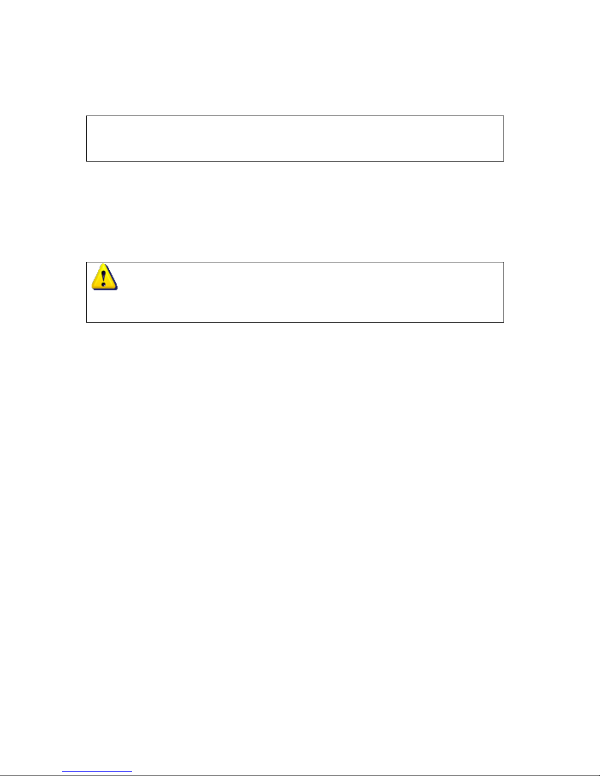
3. Minimum Manifold Pressure adjustment
◆Adjust Dip Switch 1 to OFF position,
◆Use a small crossing screw driver adjust The Adjustable Resistance of PCB which marked
“MIN”, to meet the data of De-rating Manifold Min. Pressure from the De-rating Manifold
Pressure Table.
◆Then adjust Switch 2 to OFF position.
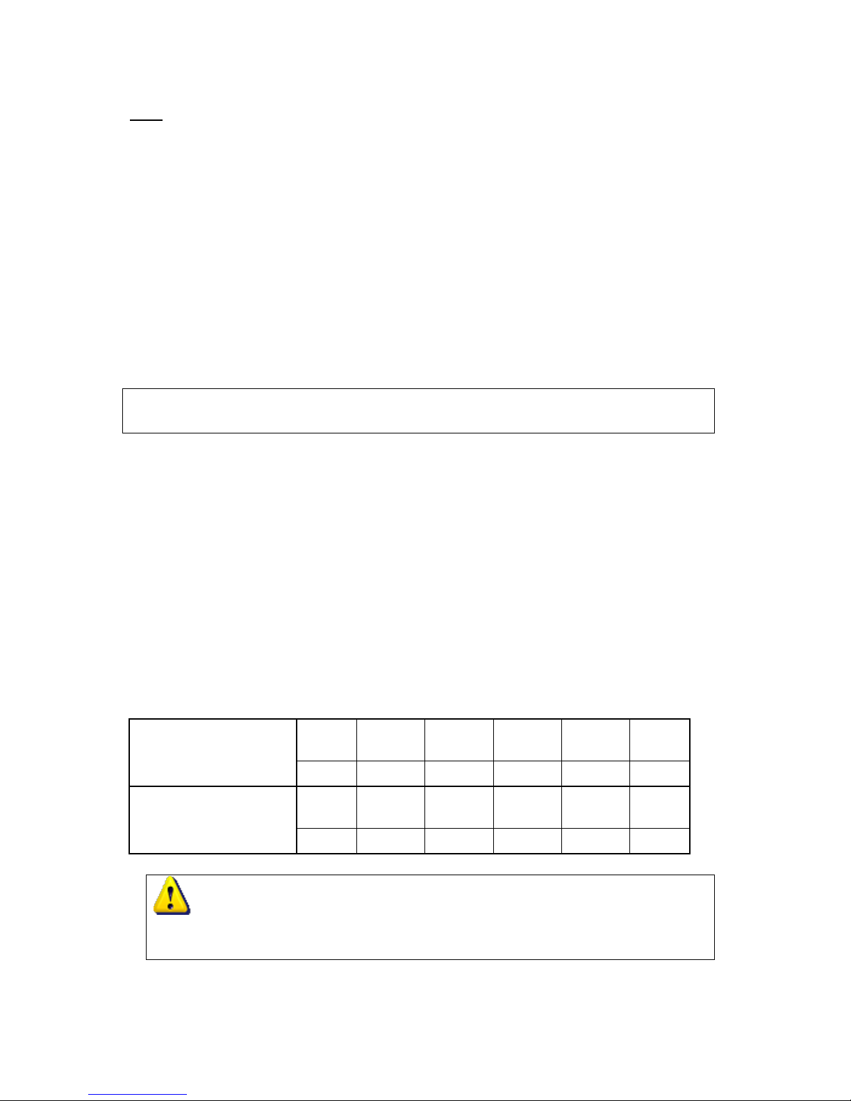
4. Check Manifold Pressure
◆Shut off all water taps, and unplug water heater’s power cord.
◆Plug the power cord and turn on all water taps, check the Maximum and Minimum
Manifold Pressure again as Step 2 and Step 3.
◆Seal back Manifold Pressure measuring point.
Water Connections
When facing the heater, the cold water inlet is on your right and the hot water outlet is on your left.
Although water piping throughout your structure may be other than copper, we recommend that
copper piping be used for at least three feet before and after the heater (follow local codes). Keep
water inlet pipe to no less than 3/4” diameter to allow the full flow capacity.
Remember that water pressure must be sufficient to activate the heater when drawing hot water
from the top floor. If the hot and cold connections to the heater are reversed, the heater will not
function. 3/4’’Copper or brass fittings work best when connected to the connectors. (See Fig. 2) The
flexible type connectors will make instillation easier and seals to the water valve by means of a
union connection with a washer type gasket at the joint. No pipe dope or thread tape is to be used at
this joint. Be certain there are no loose particles or dirt in the piping. Blow out or flush the lines
before connecting to the ECOHOTTM. Full port valves should be installed on both the cold water
feed line and the hot water outlet line to facilitate servicing the heater. For installation on a private
well system, be sure that the water pressure is set between 30 and 50 PSI. (See Fig. 2) Plumbing
connections for the ECOHOTTM
Connecting the pressure relief valve (PRV) (PRV Must be Brass, ¾” and, rated at 150 PSI),
Install PRV discharge line 6” above floor drain or to exterior of home (check local building codes).
(See Figure 2) A listed pressure relief valve must be installed at the time of installation and needs to
be ¾” and 150PSI. No valve is to be placed between the PRV and the heater. No reducing coupling
or other restriction may be installed in the discharge line.
The discharge line must be installed such that it allows complete drainage of both the pressure relief
valve (PRV) and the line to a suitable place for disposal.
The location of the PRV must be readily accessible for servicing or replacement, and be mounted as
close to the water heater as possible. See Fig. 2. To install the PRV, a suitable fitting connected to an
extension on a “T”fitting can be sweated to the hot water line. (See Fig. 2)
(PRV is included with this water heater for Canada only).
OPERATING INSTRUCTIONS
Before proceeding with the operation of the heater make sure that the system is filled with water.

Installation Manual and Owner’s Guide WHO-321064-NG, WHO-321064-LP
ECOHOT TM
12 of 27
Open the cold water inlet supply to the heater fully. Open a hot water faucet to permit the water to
fill the heater and the piping and to eliminate the air trapped in the system. Close the hot water
faucet after the water flows freely and all the air has escaped from the system. The water heater is
now ready to operate.
FOR YOUR SAFETY READ BEFORE OPERATINGYOUR HOT WATER HEATER
WARNING: If you do not follow these instructions exactly, a fire or explosion may
result causing property damage, personal injury or loss of life.
WHAT TO DO IF YOU SMELL GAS
-Do not try to light any appliance.
-Do not touch any electric switch.
-Do not use any phone in your building
-Immediately call your gas supplier from a neighbor’s phone or cell phone from outside the
building and follow the gas supplier’s instructions.
-If you cannot reach your gas supplier, call the fire department.
MAINTENANCE AND SERVICE
WARNING: Unplug the electrical power supply and close the manual gas control valve and
the manual water control valve and turn off remote before servicing.
Immediately after installation:
1. Check for gas leaks with soapy water solution.
2. Check that the water heater is mounted securely.
3. Check the gas pressure.
4. Keep the area around the water heater clear. from combustible materials, gasoline and other
flammable vapors and liquids. Check every month for overgrown vegetation.
5. The appliance should be checked once a year or as necessary by a licensed technician. If
repairs are needed, any repairs should be done by a licensed technician.
CAUTION: Label all wires prior to disconnection when servicing controls. Wiring error can
cause improper and dangerous operation. Verify proper operation after servicing.
The following systems and parts should be checked at least once a year:
1. Venting system
2. Burner
3. Manual operation of the pressure relief valve to ensure correct operation. When operating
the pressure relief valve, avoid contact with hot water coming out and avoid water damage.
4. Cleaning
5. Heat exchanger requires flushing with a descaling solution. Scale build up will void your
warranty and shorten the life of your water heater. To remove the front cover, first remove
the four screws, and then pull main cover out toward you and lift up and out.

Installation Manual and Owner’s Guide WHO-321064-NG, WHO-321064-LP
ECOHOT TM
13 of 27
THE FOLLOWING OPERATIONS SHOULD ONLY BE PERFORMED BYA LICENSED
TECHNICIAN.
Venting System: Should be checked annually. Clean as needed. Before removing cover appliance
should be unplugged, Water and gas valve should be shut off.
Main Burner Flames: The main burner flames should be blue. Yellow flames could be a sign of
wrong size gas orifices or dirty burners, or a blockage on the heat exchangers fins. If some burners
have yellow flames while others have blue flames, it is likely that dust, lint or spider webs have
partially clogged the burner ventures. To clean the burners, contact a gas service person.
Cleaning: The water heater should be cleaned annually, keep the dust away from flue gas
passageway. See the Cleaning Instructions below.
DANGER: Hot water heater temperature over 125°F can cause severe burns instantly
or death from scalding. Children, the disabled and the elderly are at the highest risk of being
scalded. Feel water temperature before bathing or showering.
WARNING: Read and follow water heater warnings and instructions. If owner’s
manual is missing or damaged contact the retailer or go to “Greenworksunlimited.com” for a
copy.

Installation Manual and Owner’s Guide WHO-321064-NG, WHO-321064-LP
ECOHOT TM
14 of 27
Mineral Scale Build-up: The ECOHOTTM Water heater should be set at lower temperature
(ECOHOTTM Recommends 120F/49C or less) to help avoid accumulating mineral built-up. If
however the water has a high mineral content, periodic descaling may be necessary. The heating
coils should be flushed with a descaling solution. The descaling is done only to the heat exchange
or the chemicals will damage other parts.
NATIONAL SECONDARY DRINKING WATER REGULATIONS
This part establishes National Secondary Drinking Water Regulations pursuant to section 1412 of

Installation Manual and Owner’s Guide WHO-321064-NG, WHO-321064-LP
ECOHOT TM
15 of 27
The Safe Drinking Water Act, as amended (42 U.S.C. 300g–1). These regulations control
contaminants in drinking water that primarily affect the aesthetic qualities relating to the public
acceptance of drinking water. At considerably higher concentrations of these contaminants, health
implications may also exist as well as aesthetic degradation. The regulations are not Federally
enforceable but are intended as guidelines for the States.
These are the secondary maximum contaminant levels for public water systems:
Contaminant
Level
Aluminum
0.05 to 0.2 mg/l.
Chloride
250 mg/l.
Color
15 color units.
Copper
1.0 mg/l.
Corrosivity
Non-corrosive.
Fluoride
2.0 mg/l.
Foaming agents
0.5 mg/l.
Iron
0.3 mg/l.
Manganese
0.05 mg/l.
Odor
3 threshold odor number.
pH
6.5–8.5.
Silver
0.1 mg/l.
Sulfate
250 mg/l.
Total dissolved solids (TDS)
500 mg/l.
Zinc
5 mg/l.
These levels represent reasonable goals for drinking water quality. The States may establish
higher or lower levels which may be appropriate dependent upon local conditions such as
unavailability of alternate source waters or other compelling factors, provided that public
health and welfare are not adversely affected. If levels are higher than in this chart provided
you may want to talk with local Water Department, Well Driller Companies, Building
Department, or Local Government to determine if water treatment / conditioning may be an
option to reduce scaling in this water heater.
Greenworks Unlimited suggests installing a water softener if water is more than 11
GRAINS per gallon.
NOTE: Keeping this water heater controller set at 110°F to 115°F will significantly reduce
scaling to the water lines in less than favorable conditions.

Installation Manual and Owner’s Guide WHO-321064-NG, WHO-321064-LP
ECOHOT TM
16 of 27
TROUBLE SHOOTING
Introduction:
The ECOHOTTM burner is activated by a water flow valve. Numerous water related problems can
cause this water valve to malfunction such as:
1. Insufficient water flow volume to activate the burners at its minimum flow requirement.
2. Dirt in the water flow valve causing it to malfunction.
3. Sediment build-up in faucet, or shower head.
4. Uneven pressure between cold and hot (with single valve faucets).
5. Plumbing crossovers.
These water flow related problems can cause the heater to deliver less than its full output, or to fail
to ignite or to shut down completely. (Always unplug power supply before removing cover.)
No spark at the pilot:
Cross over in water lines. To confirm there is no cross-over in the plumbing, shut off the cold
water supply to the ECOHOTTM and open a hot water faucet. There should not be any water
flowing at any faucet. Water running is a sign of a plumbing cross-over. Consult your plumber.
Water flow is not sufficient to activate heater.
1. Water flow rate at faucet is below minimum flow needed to activate this appliance do to
clogged screens/filters or restricted water pipes. Consult your plumber.
2. Water inlet screen is clogged. Water flow is restricted, preventing needed flow to activate heater.
Clean water inlet screen (See Fig. 1).
3. Water valve parts may be dirty or components damage, water valve and component parts must
be completely free of dirt. In hard water areas water valve parts may be corroded to a point
where they will need replacing. Check for any sign of moisture or corrosion is at the joints of
the water valves and/or components. Replace or service if needed immediately.
4. Poor circuit connections at the Over Heat Sensor (ECO) or the flue gas safety device.
Ignition sparker will not operate if the electrical circuit is interrupted. Check that the
connections to the ECOHOTTM and “Flue Gas Safety Device”are secure.
SPARKAPPEARSAT PILOT WHEN HOT WATER TAPTURNED ON, BUT PILOTAND
BURNERS WILLNOT IGNITE.
Note: Air in the gas line is normally a problem at time of initial installation, after the pipes
have been worked on, or after a gas supply line has been allowed to empty. Bleed the air
trapped in the gas line by turning the hot water faucet on and off until the air has been
cleared from the line.
No gas to the ECOHOTTM
1. Gas cock on gas line may not be open.
2. Gas regulator may be shut or damage. Replace or unlock the regulator. Excessive pressure
will lock it up. Locking usually happens when using propane gas if the gas pressure
between the gas tank and the water heater’s gas regulator has not been reduced. To unlock

Installation Manual and Owner’s Guide WHO-321064-NG, WHO-321064-LP
ECOHOT TM
17 of 27
a regulator, consult your gas supplier or call ECOHOTTM at 1-877-5ECOHOT
(1-877-532-6468)
3. Pilot orifice or gas valve is dirty. Clogging of the pilot burner can be caused by dust in the
air or dirt in the gas. The pilot orifice or gas filter may need to be cleaned or replaced.
Flow:
The flow rate through the ECOHOTTM is limited to a maximum of 8.4 GPM at 45°F rise. The
temperature of the water will determine the flow rate output of the appliance based on your
local ground water temperature and your desired outlet water temperature combination.
Based on the Applianceed States Department of Energy method of testing water heater output,
the ECOHOTTM is rated for 348 Gallons per hour (GPH) or 5.8 Gallons per minute (GPM),
when raising the water temperature by 65°F (for example from 54°F to 115°F). Refer to the
following chart of typical household plumbing fixture flow rates to determine what
ECOHOTTM can do in a household application.
(Actual water flow will be higher when mixed with cold water)
Household Flow Rates: Taken from UPC 1997
Appliance/ Use
Flow Rate (GPM)
Appliance/ Use
Flow Rate(GPM)
Lavatory Faucet
1.0
Kitchen Sink
1.5
Bath Tub
4.0
Dishwasher
1.5
Shower
2.0
Washing Machine
2.0
TEMPERATURE SETTING
There is a remote temperature gage with digital display from 95°F (35°C) to 140°F ( 60°C).
Greenworks UnlimitedTM recommends temperatures stay at or below 120°F to prevent lime build-up
inside the “heat exchangers” copper lines.
WARNING
To help prevent scalding the outlet hot water temperature of the ECOHOTTM we recommend
setting the temperature at a maximum of 120°F (49°C)

Installation Manual and Owner’s Guide WHO-321064-NG, WHO-321064-LP
ECOHOT TM
18 of 27
FREEZE PROCTECTION DEVICES
This appliance comes equipped with heating blocks to prevent freezing which can damage the heat
exchanger. For this freeze prevention system to operate there has to be electrical power to the
appliance. Damage to the heat exchanger caused by freezing temperature due to power loss is not
covered under the warranty. This water heater has been rated for temperatures down to 5°F (-15°C)
in wind free environment. If you install the water heater in an area that is subject to temperatures
(including wind chill) below 5°F (-15°C), this will void warranty and ECOHOT will not be
responsible for any damage to the heat exchanger as a result of freezing.
If you will not be using your heater for a long period of time or if the temperature (including the
wind chill) drops below 5°F (-15°C) turn off your heater and drain the appliance of water.
Error Code
Error
Code
Description
Reasons/Repair
E0
Inlet water temperature
sensor.
◎Possible short in sensor/may need replacement of
sensor/check wire to water temperature sensor it may be
disconnected.
E1
Ignition fail or lost flame
◎Hardware error in detecting the flame feedback/check gas
supply/call ECOHOT.
◎No flame detection after ignition 6 seconds/check gas
supply/call ECOHOT
◎Lost flame when burning/check gas supply/call ECOHOT
E2
Communication Error
◎Hardware error in PCB controller/call ECOHOT.
E3
Fan voltage error
◎Fan driver error, cannot detect voltage or current/check
power supply.
◎Vent pipe is blocked or wind pressure is to high/check
flue pipe-exhaust for blockage/call ECOHOT.
E4
Fan error
◎Fan not working/check power supply.
◎Low fan speeds/check for blockage of exhaust/call
ECOHOT
E5
Overheat
◎Water temperature more than (185°F/ 85°C)/outlet water
temperature sensor not working/thermostat is not working
properly/loose wire to sensor/call ECOHOT
E6
Outlet water temperature
error
◎Possible short in sensor/may need replacement of
sensor/check wire to water temperature sensor it may be
disconnected.
E7
Selection switch error
◎Controller board error/ Call ECOHOT
E8
Heat Exchanger temp
sensor error
◎Possible short in sensor/may need replacement of
sensor/check wire to water temperature sensor it may be
disconnected.
F1
Hi Limit thermostat open
◎Controller board error/ Call ECOHOT
F2
Gas Valve driver circuit
◎Controller board error/ Call ECOHOT

Installation Manual and Owner’s Guide WHO-321064-NG, WHO-321064-LP
ECOHOT TM
19 of 27
error
F3
The power of Gas Valve
error
◎Controller board error/ Call ECOHOT
F4
Main Valve control
circuit error
◎Controller board error/ Call ECOHOT
F5
Proportional Valve driver
circuit error
◎Controller board error/ Call ECOHOT
F6
AD converter error
◎Controller board error/ Call ECOHOT
F7
Setting Switch error
◎Controller board error/ Call ECOHOT
◎The error status will keep locked until the “On/Off” is pressed or if you reopen the water flow.
◎Error “E7” will keep this appliance locked to unlock turn off and then back on or unplugged this
appliance and plug in again.
◎The Beeper will beep 3 times per second whenever error happens.
Call ECOHOT Tech Support 1-877-5ECOHOT (1-877-532-6468)

Installation Manual and Owner’s Guide WHO-321064-NG, WHO-321064-LP
ECOHOT TM
20 of 27
PARTS LIST
No
Part Code
Part Name
Quantity
Remark
203
JSW32AU05_04
Flue gas collector
1
204
010466
Heat exchanger assembly
1
205
T1/11
Hi-limit thermostat (80°C)
1
206
JSG32AU05_DL11
Hi-limit and fuse connector
1
207
JSG32AU05_DL07
Flame feedback cord
1
208
DHS-M4
Ignition assembly
1
209
JSQ32A_07
Combustion chamber cover
1
210
JSG32AU05_03Bx
Gas tube appliance
1
x=1:NG , x=2:LPG
211
JSG32AU05_DL14
Ignition Assembly cord
1
212
JSQ24A_07
Gas valve assembly
1
213
JSG32AU05_DL05
Transformer assembly
1
214
FY6215I_00
Wind Pressure Switch
1
215
JSG32AU05_09
Water control assembly
1
216
JSG32AU05_DL15
Wind pressure switch cords
1
217
JSG32AU05_DL04
Gas Valves cords
1
218
JSR10.07
Inlet gas connector
1
219
JSG32AU05_12
Inlet water connector
1
220
JSG32AU05_DL10
Valve cord assembly
1
221
JSG32AU05_DL08
Remote controller connector
1
222
JSG32AU05_13
Outlet water connector
1
223
Y01KO3000SE2_DL01
Power cable assembly
1
224
JSG32AU05_DL13
Outlet water temperature sensor
1
225
JSG32AU05_10
Fan assembly
1
227
JSG32AU05_04
Combustion chamber
1
228
JSQ32A_05
Burner assembly
1
229
GB845-85
Cross self-taping screws
2
ST2.9*8
230
JSQ32A-4
Fuse support
4
3Cr13δ0.4
231
JSQ24A-11
Protection tube
4
232
GB9074.3
Cross screws
26
M4*8
233
JSQ16A-3
Sealing tape
2
PP δ2
234
JSQ24A-8
Proportional valve O-ring 1
1
φ24.8×φ.5
235
JSQ24A-9
Proportional valve O-ring 2
1
φ20.8×φ3.5
236
SJ2829-87
Cross screws
1
M4*6
237
JSPQ10C.06-1
Washer
1
δ1
238
JSG32AU05-2
Proportional valve testing tube
1
HPb59-1
239
JSQ32A-1
Transformer board
1
240
SJ2829-87
Cross screws
4
M4*10
241
WHG8BHK_00-4
Plastic washer
4
This manual suits for next models
1
Table of contents
Popular Water Heater manuals by other brands

MAXXMEE
MAXXMEE 04900 Assembly and operating instructions

Sinclair
Sinclair SWH-200DE Service and installation manual

STIEBEL ELTRON
STIEBEL ELTRON DHB-E 16-2 installation instructions

Bradford White
Bradford White UPV75 Series Service manual

Shini
Shini STM-PW series manual

Paloma
Paloma PH-28RIFSN Installation and operating instruction manual

inventum
inventum HotSpot Titanium 40131500 manual

PrecisionTemp
PrecisionTemp ShowerMate-550 user manual

LIVINOX
LIVINOX WH T Series Operation manual

NorthStar
NorthStar 157495 owner's manual

Viessmann
Viessmann Vitocell 100-E Installation and service instructions

John Wood
John Wood JW6058 Series Installation and operating instructions