MANUAL
MANUAL MANUAL
MANUAL
ILARIA ILARIA
ILARIA
ILARIA
7.3.1. Ignition phase
The stove is started by pressing the ON/OFF button for a few seconds. The procedure starts
by activating the ignition heater and continuously filling the pellets using the screw. The display
shows, in sequence, the messages ACCENDE [IGNITION], CARICA PELLET [FEEDING PEL-
LETS] and ATTESA FIAMMA [AWAITING FLAME]. After around 50 seconds (parameter Pr55), the
gear motor stops and the exhaust fan is started (at the speed set by parameter Pr16). Once the
pellets have been ignited and the flue gas temperature reaches 50°C (parameter Pr13), the heater
switches off and the flame stabilisation phase starts. The ignition phase ends when the tempera-
ture reaches 50°C, however for safety reasons and to protect the heater, this phase can last a
maximum of 16 minutes (parameter Pr02). If the pellets are not ignited, that is, the stove does
not reach 50°C in the 16 minutes available, the display will show the “MANCATA ACCENSIONE”
[FAILED IGNITION] alarm.
7.3.2. Flame stabilisation phase
In this phase, the screw conveyor feeds the pellets at the preset speed (parameter Pr05). When
the flue gas temperature exceeds 110°C (parameter Pr11) with a ramp of 3°C/minute, the stove is
ignited. In this flame stabilisation phase, the flue gas exhaust fan reaches the preset speed (pa-
rameter Pr17) and the temperature is measured to make sure it remains stable for a certain time
(parameter Pr02); after this, the operating phase starts. The initial start-up phases can be skipped
by holding button P2 (increase heat) for around 3 seconds; this automatically skips to the normal
operation phase.
7.3.3. Operating phase
The board has an input for an external thermostat. The operating mode of the stove changes ac-
cording to the external thermostat setting, the room thermostat setting and the room temperature
measured.
T
Amb
:
room temperature measured by the probe
T
SetAmb
:
room temperature set for the SET TEMP AMBIENTE [ROOM SET TEMP]
T
SetTerm
:
room temperature set on the external thermostat
• :
External thermostat closed (TAmb > TSetTerm): The display shows the message “ton” and the
stove works at the set heat output until the thermostat opens.
• :
External thermostat open (TAmb < TSetTerm): The stove works at the set heat output until
reaching TSetAmb (TAmb < TSetAmb), after which the economy phase starts (TAmb > TSetAmb).
-15- -16-
-15- -16-
7.3.1. Ignition phase
The stove is started by pressing the ON/OFF button for a few seconds. The procedure starts
by activating the ignition heater and continuously filling the pellets using the screw. The display
shows, in sequence, the messages ACCENDE [IGNITION], CARICA PELLET [FEEDING PEL-
LETS] and ATTESA FIAMMA [AWAITING FLAME]. After around 50 seconds (parameter Pr55), the
gear motor stops and the exhaust fan is started (at the speed set by parameter Pr16). Once the
pellets have been ignited and the flue gas temperature reaches 50°C (parameter Pr13), the heater
switches off and the flame stabilisation phase starts. The ignition phase ends when the tempera-
ture reaches 50°C, however for safety reasons and to protect the heater, this phase can last a
maximum of 16 minutes (parameter Pr02). If the pellets are not ignited, that is, the stove does
not reach 50°C in the 16 minutes available, the display will show the “MANCATA ACCENSIONE”
[FAILED IGNITION] alarm.
7.3.2. Flame stabilisation phase
In this phase, the screw conveyor feeds the pellets at the preset speed (parameter Pr05). When
the flue gas temperature exceeds 110°C (parameter Pr11) with a ramp of 3°C/minute, the stove is
ignited. In this flame stabilisation phase, the flue gas exhaust fan reaches the preset speed (pa-
rameter Pr17) and the temperature is measured to make sure it remains stable for a certain time
(parameter Pr02); after this, the operating phase starts. The initial start-up phases can be skipped
by holding button P2 (increase heat) for around 3 seconds; this automatically skips to the normal
operation phase.
7.3.3. Operating phase
The board has an input for an external thermostat. The operating mode of the stove changes ac-
cording to the external thermostat setting, the room thermostat setting and the room temperature
measured.
T
Amb
:
room temperature measured by the probe
T
SetAmb
:
room temperature set for the SET TEMP AMBIENTE [ROOM SET TEMP]
T
SetTerm
:
room temperature set on the external thermostat
• :
External thermostat closed (TAmb > TSetTerm): The display shows the message “ton” and the
stove works at the set heat output until the thermostat opens.
• :
External thermostat open (TAmb < TSetTerm): The stove works at the set heat output until
reaching TSetAmb (TAmb < TSetAmb), after which the economy phase starts (TAmb > TSetAmb).
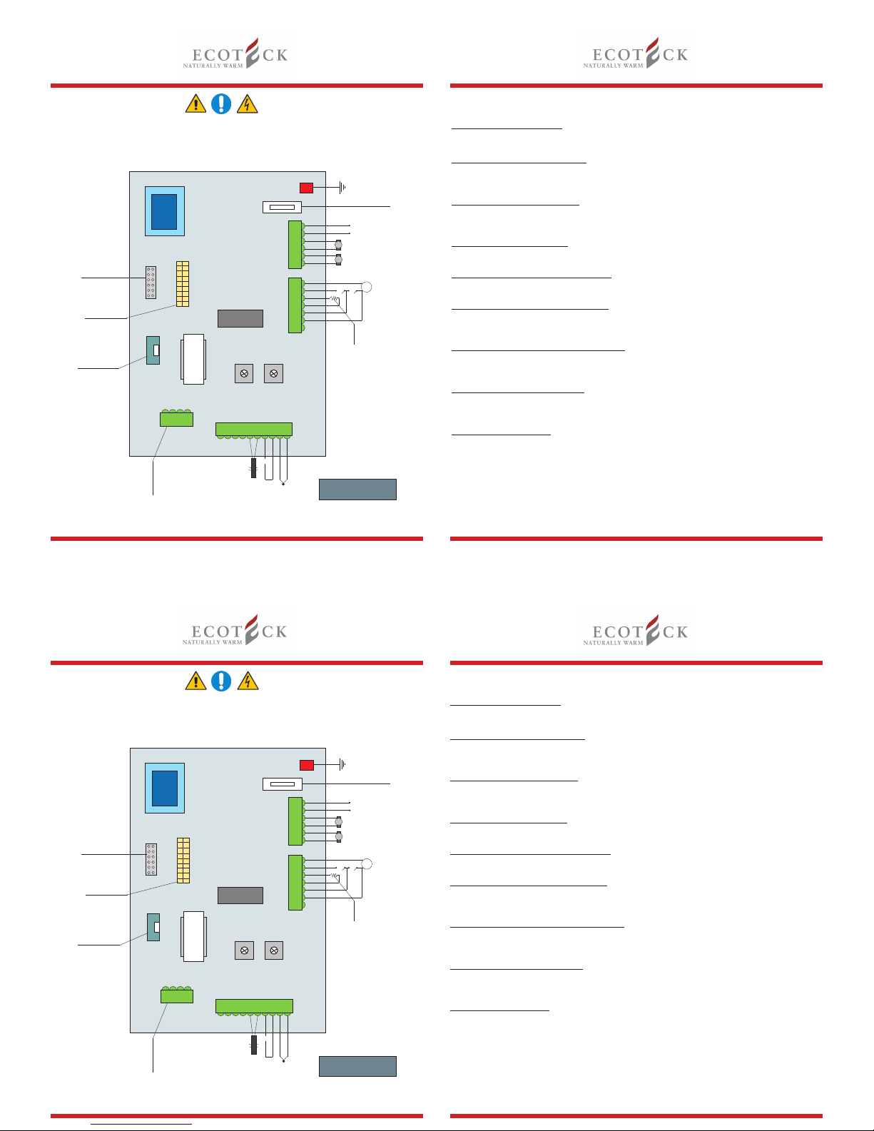
Display
The LCD shows all the messages required for the operation of the stove.
IR Receiver
IR receiver for remote control (optional).
7.2. User functions
7.2.1. Setting the heat output
The heat output is set using buttons P1 and P2 on a value between 1 (minimum) and 5
(maximum). The selected value is shown on the display. The setting can be made at any time,
both before the ignition of the stove and when the stove is in operation, but not in the economy
phase (see the paragraph on Economy phase).
7.2.2. Setting the temperature
The temperature setting can be made using buttons P4 and P5, between a minimum value of 7
and a maximum value of 40. The selected value is shown on the display. The setting can be made
at any time, both before the ignition of the stove and when the stove is in operation.
7.2.3. Settaggio della miscela pellet-aria.
Setting the air - pellet blend allows the speed of both the smoke engine and the pellet feeding
screw to be changed simultaneously. This allows combustion to be adjusted according to the
stove’s draught and according to the hardness of the pellet. To access adjustment press P6 and
P7 together until “0 PELLET 0 DRAUGHT” appears.
The quantity of pellet is changed with keys 4 and 5.
The speed of the smoke engine is changed with keys 6 and 7.
This screen will appear on the display
N.B. They are two independent headings!
7.3. Staring the stove
The stove is started and stopped manually by pressing button P3 (ON/OFF) for a few seconds. A
complete operating cycle usually involves five separate phases (ignition, flame stabilisation, normal
operation, economy and shutdown) which alternate according to the flue gas temperature measured
and other operating parameters. These phases are explained in detail below.
0
PELLET
0
DRAUGHT
Valori Pellet
From 0 to -5 i decrease the pellet load
0 Default value that considers the set combustion as excellent
From 0 to 5 i increase the falling pellet
Valori Tiraggio
From 0 to -5 To be carried out when there is too much draught and when there is no ame in the stove
0 Default value that considers the set combustion as excellent
From 0 to 5 To be carried out when the pellet to be used is too hard and a stronger draught is required
in the combustion chamber
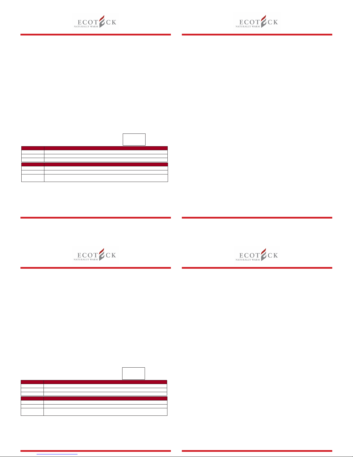