Edge Products Insight Pro User manual


4 Read Me
4 Safety Warning & Caution
5 Safety Guidelines
6 At a Glance
6 Physical Overview - The Display
7 Accessories
8 Touch Screen Gestures
9 Menu Icons
9 Common Terms
10 Getting Started
10 Download the Ignition Update Software
11 Using the Ignition Update Software
12 Cable Installation
12 Windshield Mount Installation
13 Installing the Display
14 Display Set Up
14 OEM Selection Menu
15 Entering the Quick Link Menu
16 Entering the Pull Down Menu
17 Changing the Default Background Image
18 ConguringtheHomeScreens
20 Using the Switch Screen - Toggle Switches
22 Individual Gauge Setup
23 Calibrating Pitch, Roll, & G-Force Gauges
24 Download and Install MyStyle Software
25 Adding Custom Background Images
26 Performance Tuning
26 Read Me
27 Custom Tuning Process - At a Glance
28 Read Vehicle Stock
29 Loading Custom Tunes
31 Programming your Vehicle
32 Settings
32 Accessory Options
36 Vehicle Options - Tire Size
37 Alert Options
38 Sound Duration - Alerts
38 Backlight Auto dim
39 Menu Time out
39 Units
39 Factory Reset
Table of Contents

40 Diagnostics
40 Read DTCs
41 Clear DTCs
41 Clear On Start
42 Manual DPF Regeneration
44 DPF Regeneration Explained
45 Injector Balance Rates
46 Performance Testing
46 0-60 & Quarter Mile
47 Horsepower
48 Data Log
48 Data Logging Explained
49 Retrieving Data Using MyStyle
50 Records
50 Records Explained
51 Help
51 HelpMenuExplained
52 Maintenance Manager
52 Turn on Maintenance Manager
53 Entering the Odometer Value
54 Setting the Alert Threshold
55 Customizing Maintenance Items
56 Mileage Coach
56 Mileage Coach Set Up
58 Additional Features
58 EFI Live™
58 Smarty-POD™
59 EAS 12V Power Kit
60 Appendix
60 Limited 1 Year Warranty
61 Important Information about your Vehicle’s Warranty
62 Commonly Used Acronyms
63 Trouble Shooting Guide
63 OEM EGT Locations - Diesel Trucks Only

4
Safety Warning & Caution
Read Me
Throughout this User Manual you will see important messages
regarding your safety or the protection of your vehicle. These
messages are designated by the words WARNING, CAUTION, or
NOTICE.
A WARNING indicates a hazardous situation which, if not avoid-
ed, will result in death or serious injury.
A CAUTION indicates a hazardous situation which, if not avoided,
could result in minor or moderate injury.
NOTICE
A NOTICE indicates a condition that could cause damage to the
product or your vehicle.
The Edge Product you have purchased is a high-performance
product. As such, it does present some risks of which you should
be fully aware. Do not use this product until you have carefully
read the following safety information and the Owner Agreement.
NOTE: After the display has been installed, a warning screen
will appear (3) different times.
If you agree with the agreement, select Yes to continue.
Read Me
WARNING: Misuse of this device could lead to a
serious accident. Do not use to break legal speed limits.
Before installing, read and comply with all information in the
User Guide. Do you agree?
WARNING
CAUTION

5
Safety Guidelines
Before using device, read and understand the user manual,
including these additional safety instructions. Failure to do so
could result in DEATH or SERIOUS INJURY.
• Your Insight Pro device is compatible with third-party custom tuning
software. Before installing third-party tuning software on your device,
refer to the third-party tuning dealer/developer’s instructions and
warnings, including any user manual or other written material, and
your vehicle’s user manual.
• Donotexceedlegalspeedlimitsonpublicroadways.Violatingtrafc
laws is dangerous and could result in injury or vehicle damage or
both.
• Use any enhanced speed capabilities of this product only in closed
circuit, legally sanctioned racing environments expressly for this
purpose.Violatingtrafclawsisdangerousandcouldresultininjury
or vehicle damage or both.
Do not operate the device while driving. Distracted driving could
resultintrafcaccidents,deathorseriousinjury,and/ordamageto
your vehicle.
• Always perform all adjustments or changes while stopped. Changing
a setting while driving can interfere with your attention to roadway
conditions and could result in injury or vehicle damage or both.
• Do not stack products. “Stacking” performance-enhancing devices
or other improper installation can cause power train failure on the
road. Other products may have features incompatible with your Edge
device. Follow all installation and operating instructions.
• Somemodicationsmayaffectotherpartsofyourvehicle.For
example, if you remove/adjust the speed limiter in your vehicle, be
sure your tires and other components are rated for the increased
speeds they will have to withstand. Not doing so can lead to loss
of vehicle control. Modify the speed limiter only for use in closed
circuit, legally sanctioned racing environments, not for use on public
roadways.
Read Me
WARNING

6
At a Glance
Ambient
Light
Sensor
Drop-down
Menu
Quick Link
Menu
Gauges
Physical Overview - The Display
HDMI
Port
Video
In
Mount
Receiver
USB port
At a Glance

7
Accessories
Windshield Mount
OBDII to HDMI cable
OBDII
EAS
HDMI
Suction
Cup
Cam
Lever
Dual-Tab
Mount
Mini USB Cable
Zip-Ties
Alcohol Wipe
Iso-
propyl
Adjustment
Nut
At a Glance

8
Touch Screen Gestures
Press Hold&Drag
Use these gestures to navigate and control the display.
TheHold&Draggesture
is used to drag up or down
menus, and scroll through
menu items.
The Press gesture is used
to select options, input
values, enter menus, etc.
Swipe
The Swipe gesture is used to
scroll through gauge screens.
At a Glance

9
Menu Icons
Icon What it does
Brings you back to the home screen
Changes the background Image
Opens the custom color picking menu
Home
Background
Custom Color
Brings you back to the previous screen or menuBack
Opens the default color picking menuDefault Color
At a Glance
Common Terms
PID - Parameter IDs
Term What it is
Data taken from a vehicle & viewed in a gauge
DPF - Diesel Particulate Filter Requiredonnewdieselstolteroutsoot
EAS - Expandable Accessory
System
Allows you to connect aftermarket sensors and
other devices such as turbo timers
ECM - Engine Control
Module
(aka ECU) A computer that controls various
sensors and engine components
TCM - Transmission Control
Module
(aka TCU) A computer that controls automatic
transmissions
PCM - Power Control
Module
(aka PCU) Combines and provides power for
the ECM and TCM

10
Download the Ignition Update Software
Getting Started
Getting Started
STEP 1 - Go to our website:
www.edgeproducts.com
STEP 2 - Click the
UPDATES tab located at the
top of the webpage.
STEP 3 - Scroll down to the
IGNITION UPDATE option
and click the DOWNLOAD
button.
STEP 4 - Click the RUN
button on the pop-up menu.
STEP 5 - Read and click the box
to accept the license agreement
terms.
STEP 6 - Click the Install
button to continue.
STEP 7 - Click the Close
button once the download is
complete.
NOTE: A desktop icon will be
created.
11
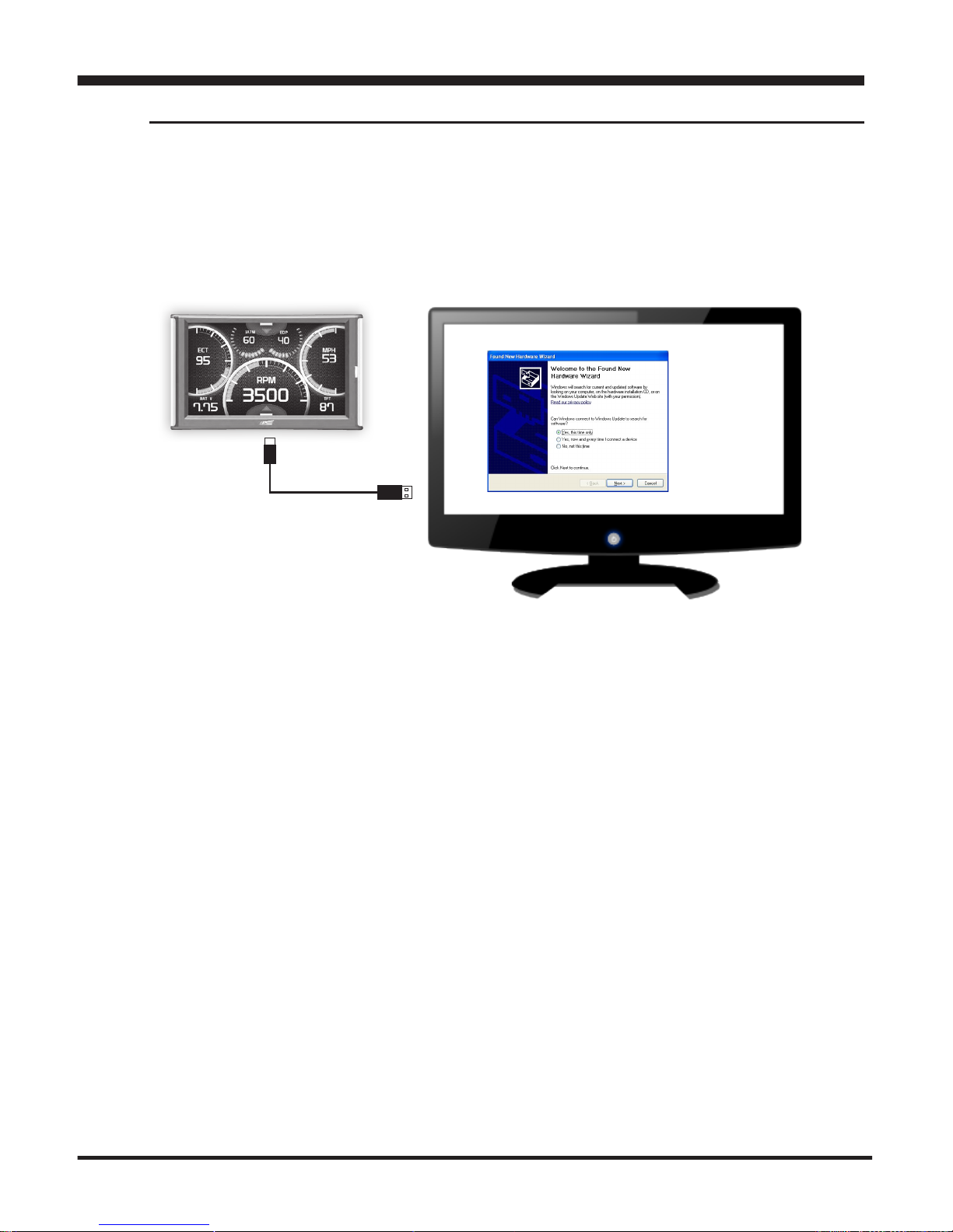
Using the Ignition Update Software
A computer with internet access is required:
STEP 1 - Double click the Ignition Icon on your desktop.
STEP 2 - When asked, plug the display into the computer
using the supplied USB cable.
STEP 3a - If an update is available, click YES to continue.
NOTICE! DO NOT unplug the display from the computer during
an update. Unplugging during an update may corrupt the device’s
software.
STEP 3b - If an update is not available, click the OK button.
STEP 4 - Once the update is complete, click Close.
Getting Started

12
Cable Installation
STEP 1 - Locate the On Board Diagnostics II (OBDII) port. (This
connector is typically found directly below the driver side dash
console.)
STEP 2 - Plug the
OBDII connector into
the vehicle port.
STEP 3 - Route the
HDMIendupthedriver
side dash.
(On most vehicles,
the side panel may be
removed to expose
the underside of the
dash for easier routing.
Leave exposed until
after the display is
installed.)
Windshield Mount Installation
HDMI
OBDII
STEP 1 - Use the Alcohol Wipe to
liberally clean the windshield in the
area you plan to place the suction cup.
Allow the glass to fully dry.
STEP 2 - Firmly press and hold the
suction mount against the glass.
Ensure proper suction before attaching
the device. Windshield mount and device
could detach during operation and result in
injury to the driver.
STEP 3 - Rotate the Cam Lever
towards the glass to create the suction.
Getting Started
CAUTION

13
Installing the Display
STEP 1 - PlugtheHDMI
connectorintotheHDMI
receptacle located on the back
side of the display.
STEP 2 - Align the Dual Tabs
on the Mount with the mount
receiver on the back side of
the display, then slide it into
place.
STEP 3 - Adjust the viewing
angle using the adjustment nut
on the mount’s swivel head.
STEP 4 - Pull any extra cable
back behind the pillar and
dash. (Re-install any panels removed
during the Cable Installation.)
Getting Started

14 Display Set Up
OEM Selection Menu
Oncetheinstallationiscomplete,andyourstplugthedevice
into the OBDII port, the OEM selection menu will appear.
Display Set Up
OEM Selection Menu:
Ford
Chrysler / Dodge
STEP 1 - Turn the vehicle to the ON or RUN key position.
STEP 2 - Select one of the available options that applies:
Ford
Chrysler/Dodge
GM/Chevy
Import (BMW, Mazda, Mini Cooper, Mitsubishi, Nissan, Subaru, Other)
EAS 12V Power Kit
STEP 3 - Follow the on screen
instructions. The Main Gauge screen will appear.
GM / Chevy
Import
EAS 12V Power Kit

15
Display Set Up
Entering the Quick Link Menu
STEP 1 - Press the lower menu tab to enter the Quick Link
Menu.
STEP 2 - The Main Menu will appear. Choose a menu option,
and Press the Icon to enter that feature menu. (Note: Each
feature menu option is shown in detail later in this manual)
Return
toHome
Screen

16 Display Set Up
Entering the Pull Down Menu
STEP 1 - Press the upper menu tab to enter the Pull Down Menu.
The following screen will appear:
Return
toHome
Screen
Change
Background
Image
Adjust
Background
Color
&
Opacity
Ifnoticationsareactive
they will be listed here.
Ifmultiplenoticationsare
active at one time they will
alternate every few seconds.
Light
Indicator
These buttons toggle the power
level which is displayed be-
tween the two.
When the Drop Down menu is closed, this tab alerts
youtoanynoticationsthatareavailablebychanging
color.

17
Display Set Up
Changing the Default Background Image
STEP 1 - Enter the Pull Down Menu.
STEP 2 - Press the Background icon.
HoneyComb Wild Fire
(Red/Blue/Green) Flash Scratched
Digital Camo
Simple
White Wash
Diamond Plate
Each press of the icon will cycle through to the next image:
Refer to the “Adding Cus-
tom Background Images”
section of this manual for
information on how to add
your own images to the
display.

18
Conguring the Home Screens
STEP 1 - Enter the Quick Link menu.
STEP 2 - Press the Screen Layout Icon
STEP 3 - Select either Layout 1 or Layout 2.
STEP 4 - Select one of the screen layout options
Display Set Up
Screen Layout
Background
Layout 1 - Master
Layout 2 - Accelerometer
Press to
select a
default
Background
image
Screen Layout
Master Digital Retro
Needles Accelerometer Switches

19
Display Set Up
Layout Options
Master Digital Retro
Needles Accelerometer
STEP 5 -ReturntotheHome screen.
STEP 6 - Swipe horizontally to switch between your selected
layouts.
Switches

20
If you have purchased an Expandable Accessory System (EAS) Power Switch,
you can use the Switch Screen to quickly toggle On or Off up to (4) different com-
ponents (e.g. light bars, pumps, winch, etc.) For proper installation of the Power
Switch, refer to the EAS Installation Manual. For information on how to operate
and customize each switch, continue below.
STEP 1 - Install the EAS Power Switch device according to the EAS Installation
Manual.
STEP 2 - Once all of the proper connections are made, turn the key to the ON
position.
The display will detect the newly installed Power Switch during boot up. Once
detected,thersttwobuttons(left)willautomaticallybepopulated.
STEP 3 - To toggle the switch On or Off, simply press the switch. The light
indicator will illuminate when the switch is On.
Using the Switch Screen - Toggle Switches
Display Set Up
6 Digital Gauges are also
available on this screen.
Refer to the
Individual Gauge
Setup section for
more information.
This manual suits for next models
1
Table of contents


