EF Helicopter Shogun 400 V2 User manual

1
The EF Helicopters Shogun 400 V2 helicopter is not intended for first-time helicopter pilots. Although it may be possible to
learn to fly using this helicopter with an experienced instructor, the helicopter is designed for more experienced pilots.
ASSEMBLY MANUAL AND SETUP GUIDE
FEATURES AND SPECIFICATIONS:
The EF Helicopters Shogun 400 V2 helicopter is distributed
exclusively by Global Hobby Distributors
18480 Bandilier Circle, Fountain Valley, CA 92708
All contents copyright © 2005, Global Hobby Distributors
Version V1.0 June 2005
Kit Product Number: 163110
●90% Factory-Assembled w/Balanced Main Rotor Blades
●Belt Drive Tail Rotor
●Lightweight Paddles
●Boom-Mounted Tail Rotor Servo
●Wide Landing Gear Stance
●Fiberglass Composite Main Frame
●Strong, Lightweight Aluminum Tail Boom
●3D-Aerobatic, Collective Pitch, 6-Channel Control
●Ball-End Control Linkages
●Extended Aluminum Battery Tray
●Durable Tail Boom Supports
●Complete Ball Bearing Set
●Online Parts Support
●Extensive Hop-Ups and After-Market Parts Available
●●
●●
●Overall Length: 780mm
●●
●●
●Main Rotor Diameter: 645mm
●●
●●
●Tail Rotor Diameter: 140mm
●●
●●
●Overall Height: 200mm
●●
●●
●Weight RTF: 520 grams (Approximate)
Shogun, the industry leader and creator of the 400-class 500 gram helicopter has once again raised the bar with the Shogun 400 V2. We've taken a
great heli and made it better with all the parts and features loyal Shogun owners have asked for! Leading this long list of upgrades is the new belt drive
system for driving the tail rotor. The belt drive provides a strength and durability level not achievable with a shaft drive design.
But we did not stop there! We packed the Shogun 400 V2 with tons of features you want! Lightweight flybar paddles make the cyclic controls fast
without loosing the stability and smoothness that makes the Shogun so rewarding to fly. We've also widened the landing gear, updated the body style,
included ball linkages for the controls, shifted the tail rotor servo position to the tail boom, and even extended the battery tray to make it easier to install
your favorite LiPO battery.
All of this, combined with our complete line of after-market accessories, as well as our extensive dealer network and online support, means you can
do whatever you want with your Shogun and we'll be there to back you up with the service and parts you want! Get a Shogun and find out what the
world of performance electric helicopters is really all about! Performance, Reliability, and Excitement!

2
WARNING - PLEASE READ BEFORE PROCEEDING
This R/C helicopter is not a toy! If misused or abused, it can cause serious bodily injury and/or damage to property. Fly only in open areas and preferably
at a dedicated R/C flying site. We suggest having a qualified instructor carefully inspect your helicopter before its first flight. Please carefully read and
follow all instructions included with this helicopter, your radio control system and any other components purchased separately.
●Just because the Shogun 400 V2 helicopter is powered by an electric motor doesn't mean that you shouldn't exercise caution when flying and
operating it. You must use the same amount of caution during use as when flying and operating a glow-powered helicopter.
●We strongly suggest that when you first begin flying the Shogun 400 V2 helicopter that you perform only basic maneuvers, such as hovering, until you
are more familiar with the setup and flight characteristics of the helicopter. This will give you time to feel comfortable with the way the helicopter reacts
to control inputs and power.
●You must be cautious when plugging the flight battery into the helicopter. Unlike glow-powered helicopters that use a clutch assembly to allow the
engine to idle without the rotor blades spinning, an electric helicopter features no such clutch. You must be sure that your transmitter is turned on and the
power/collective control stick is in the full idle position before plugging in the flight battery. This will prevent any chance of the rotor blades spinning and
harming you while plugging in the flight battery.
To enable us to better serve your needs, please include your email address with any correspondence you send to us. Your email
address will be added to our Customer Service Database so you will automatically receive free updates and tech notices for your
particular product. You will also receive repair status updates (if applicable) and other important information about your product as it
becomes available.
IMPORTANT INFORMATION ABOUT YOUR EMAIL ADDRESS
CHECK IT OUT! We urge you to come check out our website at http://globalservices.globalhobby.com. There you will find public message
boards frequented by other EF Helicopters product owners and the EF Helicopters support staff. This is a great place to learn about new products,
get help and suggestions for your current EF Helicopters products or just simply hang out and chat with people that share your same interests.
Global Hobby Distributors will not disclose the information it collects to outside parties. Global Hobby Distributors does not sell,
trade, or rent your personal information to others . Your privacy is important to us.
CUSTOMER SERVICE INFORMATION
If you should find a part missing or damaged, or have any questions about assembly, please contact us at the address below:
Global Services
18480 Bandilier Circle
Fountain Valley, CA 92708
Phone: (714) 963-0329
Fax: (714) 964-6236
Email: service@globalhobby.net
LITHIUM POLYMER BATTERY WARNINGS - PLEASE READ BEFORE CHARGING AND USE
●LiPO batteries may explode or catch fire. Serious injury can result from misuse.
●All instructions, warnings and cautions must be followed at all times. Failure to do so can lead to serious injury or fire.
●Do NOT overcharge. Maximum voltage for each pack must be followed.
●Do NOT over-discharge. NEVER discharge below minimum volts.
●Do NOT discharge at a rate greater than the maximum continuous discharge.
●Do NOT use or charge if the battery is hot.
●ONLY use a charger made for Lithium Polymer batteries.
●Do NOT charge at a rate higher than 1C. Example: if the battery’s rating is 340mAH, then the charger’s charge rate must be set at 340mAH or less.
●Do NOT leave in direct sunlight or in a hot car or storage area.
●Do NOT get wet or expose to moisture.
●Do NOT short-circuit the battery.
●ONLY discharge and charge the battery outdoors or in a fire-safe container.
●Do NOT charge with reverse polarity.
●Do NOT leave the battery connected when not in use.
●Do NOT operate or charge unattended.
●Do NOT solder to the battery directly and do not get the battery hot in any way.
●Always let the battery cool and "rest" between uses and charging.
●Do NOT charge inside your car or inside your house.
●Inspect the battery before each use for swelling or other malformation. If the cell has ballooned, it MUST be discarded.
●Set the charger to 1C (charge at 1/2C or less for the first 5 cycles).
●Check polarity and then connect battery to charger.
●In use, do not over-discharge or exceed maximum discharge.
●When handling the battery, remember not to poke, bend or damage the cell. The cell outer casing is soft and can be damaged.
●Remember, the cells must never exceed 160 degrees Fahrenheit for any reason.
3
Dean's Whip Antenna (Optional)
P/N 625112
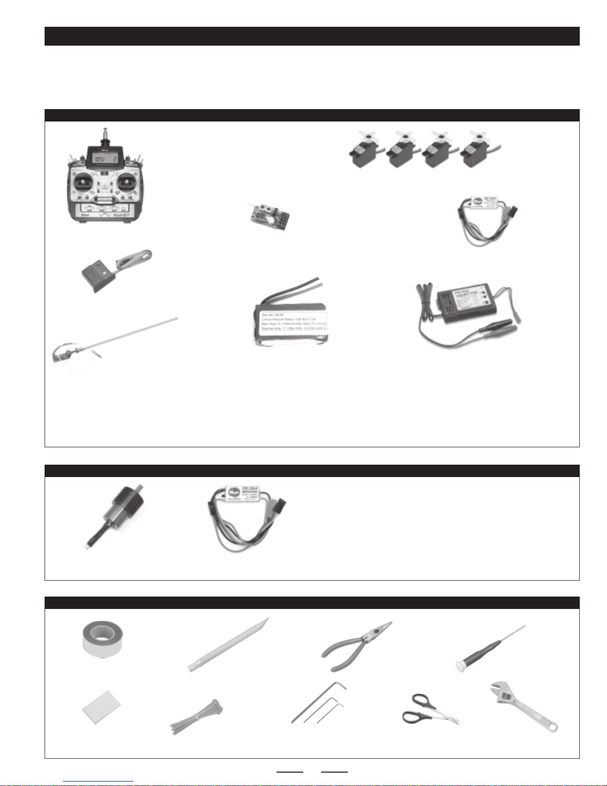
ITEMS NEEDED FOR ASSEMBLY
This section describes our recommendations to help you decide which accessories to purchase for your Shogun 400 V2 helicopter.
Remember, this helicopter is small, lightweight and 3D-capable. When choosing accessories, we suggest choosing the lightest
available. The lighter the overall weight of the helicopter, the better it will fly.
RECOMMENDED ITEMS FOR FLIGHT
Hitec Eclipse 7 Transmitter
or Equivalent
(Should Feature Throttle/Collective
Mixing & Throttle Hold)
6 Channel or More
Heli-Capable Transmitter
Cirrus CS-10BBHD Micro Servos or Equivalent
(Should Be 8-10 Grams and Feature Ball Bearings)
Cirrus MRX-6 FM Micro Receiver
or Equivalent
(Use Micro Receiver Only)
Cirrus MPG-6 Micro Gyro or Equivalent
(Use Micro Gyro Only)
TOOLS AND SUPPLIES REQUIRED
*You must use a LiPO-compatible charger to charge LiPO batteries. Do not attempt to charge LiPO batteries with a charger not specifically designed
to charge LiPO batteries.
**We recommend the EF Helicopters ESC-20AH ESC because it's designed for use with electric helicopters and specifically for LiPO batteries. This
ESC features an on/off switch, smoother start and acceleration, no motor cutoff and an ultra-bright red LED to indicate when it's time to land. It's got
a small footprint and is very light, too.
WattAge 3 Cell 1250mAH - 2000mAH
LiPO Battery or Equivalent ProPeak Quattro LiPO Charger
or Equivalent*
Double-Sided Foam Tape
Velcro®Strip
X-Acto Knife Needle Nose
Pliers
Nylon Cable Ties Assorted Hex Wrenches
Small Phillips
Screwdriver
Scissors
P/N 444053
P/N 444509
P/N 443536
Receiver uses Cirrus single
conversion FM Crystal
(not included).
P/N 128763 P/N 158370
Adjustable
Wrench
NOTE: A soldering iron and solder may be necessary if you need to change and/or add compatible plugs to your ESC and battery.
EF Helicopters ESC-20AH
Micro ESC or Equivalent**
P/N 165020
RECOMMENDED ITEMS FOR BRUSHLESS MOTOR SETUP
EF Helicopters
Brushless Motor w/Pinion Gear
P/N 165370
EF Helicopters
Brushless Micro ESC
P/N 165022
While the Shogun V2 is 3D-capable out of the box, if you really
want to ratchet up the power for ultra-extreme 3D aerobatics, we
highly suggest upgrading to our brushless power system. This
system drops right in, and it uses the same recommended LiPO
battery. The only other addition is the use of a brushless* ESC.
*You must use a brushless-compatible ESC with the brushless motor. Do
not attempt to use a standard ESC with the brushless motor. It won't work.

4
PARTS IDENTIFICATION AND FAMILIARIZATION
Now that you're familiar with the main component-parts of your new Shogun 400 V2 helicopter, it's time to get started finishing it. There's
really not much to it. Below we outline the main steps for your convenience:
●Install Your Servos
●Install Your Gyro, Electronic Speed Control and Receiver
●Install Your Battery
●Adjust the Tail Rotor Belt Tension
●Connect the Pushrod Linkages and Install the Tail Rotor Pushrod
●Install the Main Rotor Blades
●Apply the Decals
●Install the Body
●Balance the Helicopter
●Test Controls for First Flight and Set Up Your Transmitter
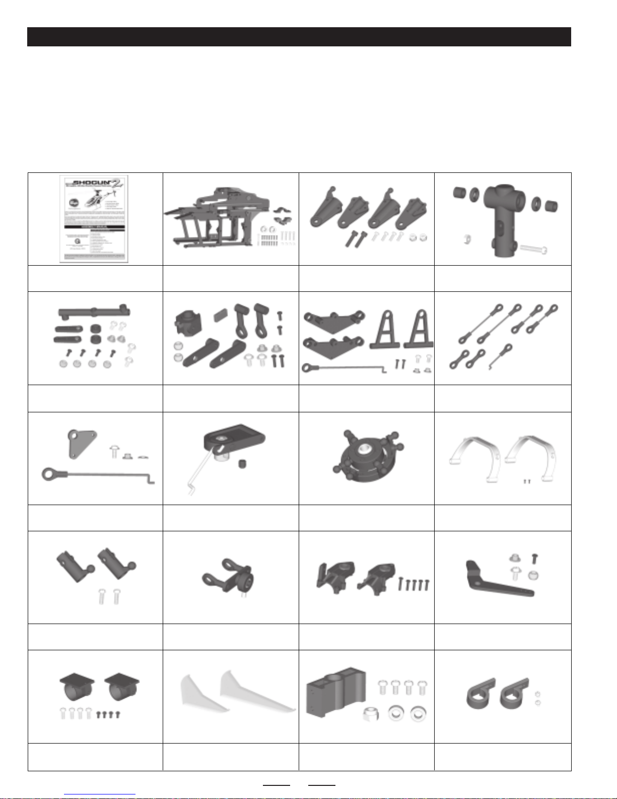
FINAL ASSEMBLY SEQUENCE
❑(A) Shogun 400 V2 Helicopter - 1
❑(B) Main Rotor Blades - 2
❑(C) Body with Clear Canopy - 1
❑(D) Tail Rotor Pushrod - 1
❑(E) Antenna Support Tube - 1
❑(F) Ball-End Mounts with Screws - 4
❑(G) Rubber Bands - 2
❑(H) Pitch Gauge - 1
❑(I) Decal Set (Not Shown) - 1
H
G
F
D
E
C
B
A
If you find any parts missing or damaged, please contact us as soon as possible,
using the Customer Service Information on page # 2.
ASSEMBLY DRAWINGS AND REPLACEMENT PARTS INFORMATION
This assembly manual includes a complete set of 3D assembly drawings, a photo-illustrated replacement parts list and a
photo-illustrated hop-ups and option parts list. These sections begin on page # 14. Please save this manual and refer to these sections
if you ever need to order replacement parts or fix any problems with your helicopter.
If you'd like to convert your Shogun 400 V2 helicopter from belt
drive to solid carbon shaft drive, please see page # 17.
5
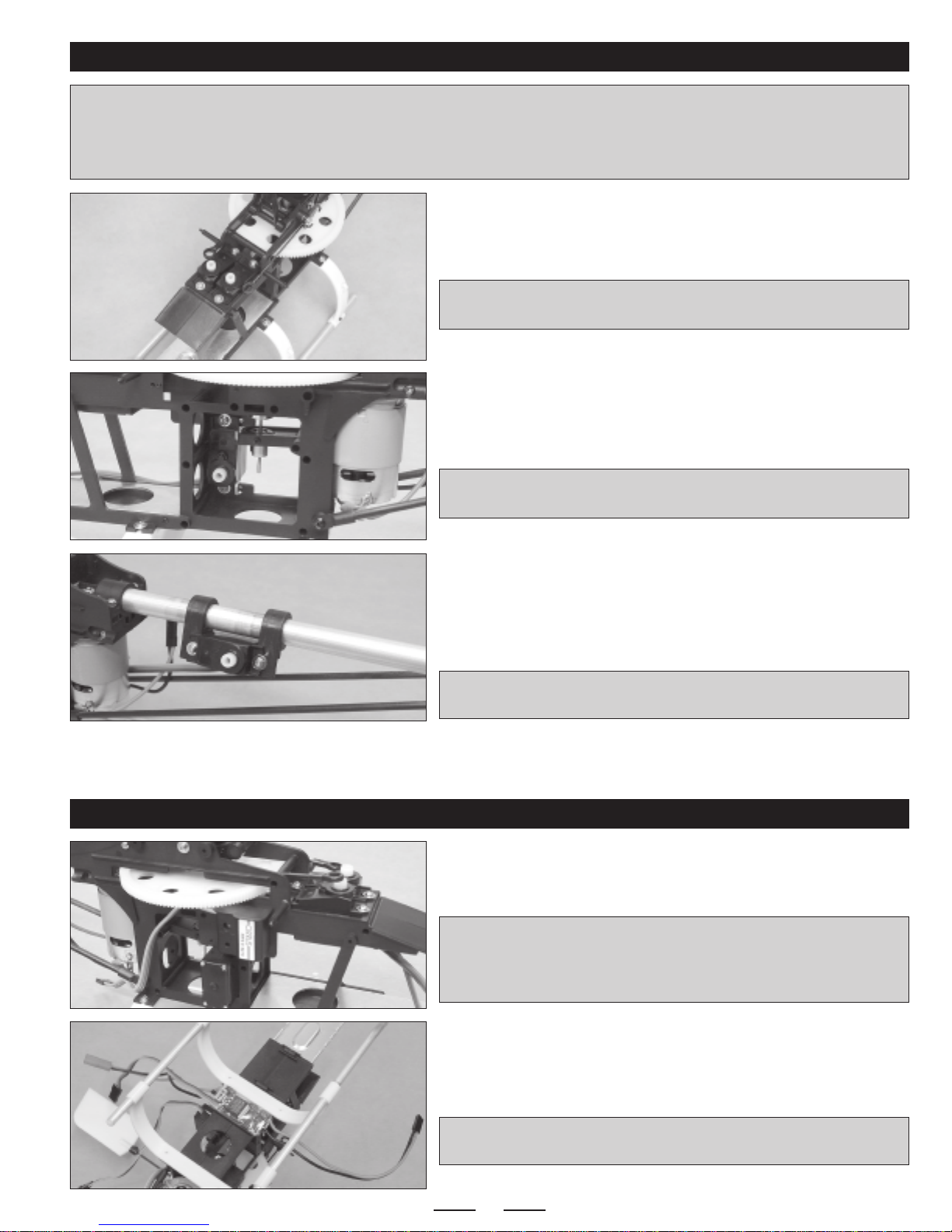
INSTALLING YOUR SERVOS
❑Install your pitch (elevator) and roll (aileron) servos into the servo mounts
at the front of the main frame.
✦✦
✦✦
✦IMPORTANT✦✦
✦✦
✦Both servo output shafts MUST be toward the FRONT of
the helicopter, so that the linkages will line up with the servo arms correctly.
✦✦
✦✦
✦IMPORTANT✦✦
✦✦
✦The helicopter frame is predrilled to fit servos with single-ended servo mounting lugs. If the servos you use have
dual-ended mounting lugs, you will need to drill new 1/16" diameter holes through the frame to install the mounting screws.
For the best control response and reliability, it's important to make sure that you use high-quality, ball bearing micro servos. We don't
recommend using bushing-supported servos, or control response and reliability will be compromised.
❑Install your collective servo into the servo mount in the side of the main
frame. If you're installing a servo with single-ended servo mounting lugs,
make sure to install the servo in the holes closest to the front of the frame.
✦✦
✦✦
✦IMPORTANT✦✦
✦✦
✦The servo output shaft MUST be toward the BOTTOM
of the helicopter, so that the linkage will line up with the servo arm correctly.
❑Install your tail rotor (rudder) servo to the two servo mounting beams on
the tail boom. Again, you may need to drill new holes through the mounting
beams to fit your particular servo.
☞You may need to loosen the screws in the servo mounting beam clamps,
so that you can adjust the width of the beams to fit your servo.
✦✦
✦✦
✦IMPORTANT✦✦
✦✦
✦The servo output shaft MUST be toward the BACK of
the helicopter.
INSTALLING YOUR GYRO, ELECTRONIC SPEED CONTROL AND RECEIVER
❑Mount your gyro to the right side of the main frame, in the small mounting
space below the main drive gear and directly above the top of the collective
servo, using a piece of double-sided foam tape.
✦✦
✦✦
✦IMPORTANT✦✦
✦✦
✦When installing your gyro, make sure to install it in the
correct direction (see your gyro installation guide for more information).
Making sure that the gyro is installed in the correct direction will ensure
that the gyro moves the tail rotor in the correct direction.
❑Mount your ESC to the bottom of the main frame, in the mounting space
directly behind the forward landing gear strut, using a piece of double-sided
foam tape.
✦✦
✦✦
✦IMPORTANT✦✦
✦✦
✦If you're using the EF Helicopters ESC-20AH, make
sure that the red LED points down so that you can see it during flight.
Continued On Next Page ☛☛
☛☛
☛
6
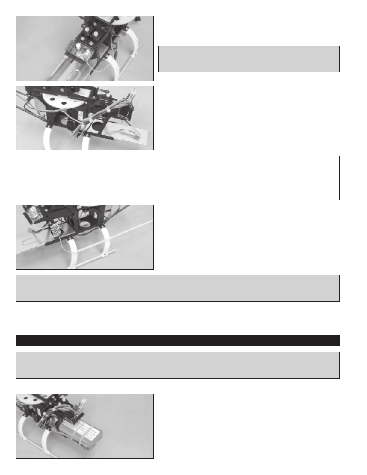
❑Mount your receiver to the mounting space in front of the pitch and roll
servos, using a piece of double-sided foam tape.
✦✦
✦✦
✦IMPORTANT✦✦
✦✦
✦Wheninstalling yourreceiver, make sure that the servo
lead mounting pins are toward the right side of the main frame. This will
make it easier to connect the servo leads.
❑Plug your servos, gyro, electronic speed control and ESC leads into their
proper slots in your receiver (see chart below).
❑Using nylon cable ties, carefully tie the servo wires together neatly to
ensure that they don't hang loose and can't interfere with any mechanical
parts, especially the main drive gear.
❑Snap the plastic antenna tube into the brackets on one side of the
landing gear struts, then run the antenna through the tube and secure it to
the vertical stabilizer, using a rubber band (not included).
☞As an alternative, you could also purchase and install a whip antenna,
like the one shown on page # 3.
✦✦
✦✦
✦IMPORTANT✦✦
✦✦
✦When securing your antenna to the helicopter, it's very important that the excess antenna cannotbe drawn into
themainrotorbladesorthe tail rotor. Because of the length of the antenna, we wrapped the first few inches around an antenna bobbin,
so that there was no excess that would hang past the tail rotor and get cut off.
Double-check with your radio control system manual forthe correct channel slots in your receiver to plug the servo leads into. Most
receivers will be like the following, but yours could differ:
Roll Servo ------------ Channel 1
Pitch Servo ---------- Channel 2
ESC Throttle--------- Channel 3
Gyro -------------------- Channel 4
Collective Servo --- Channel 6
Tail Rotor Servo---- Gyro
❑Fully charge your battery, then set it onto the battery mount and secure it
into place, using the two rubber bands included.
Continued On Next Page ☛☛
☛☛
☛
INSTALLING YOUR BATTERY
✦✦
✦✦
✦IMPORTANT✦✦
✦✦
✦Before charging your battery, it's very important to read and fully understand the warnings listed on page # 2. Failure
to understand those warnings could cause failure of your battery, resulting in damage to the battery, your battery charger or even to
yourself. Do not leave the battery unattended during the charging process.
❑If necessary, install a connector onto your battery that is compatible with the battery connector on your ESC.

7
ADJUSTING THE TAIL ROTOR BELT TENSION
✦✦
✦✦
✦IMPORTANT✦✦
✦✦
✦It's important to make sure that tail rotor belt tension is set properly. If the belt is too tight, the gears and/or the belt
could fail, and the drive-train can bind, causing loss of power and control. If the belt tension is too loose, the belt could slip and cause
loss of control.
❑Loosen the retaining screw in the side of the tail gear case, then loosen
the two upper screws that hold the tail gear case halves together.
❑Adjust the rotor belt tension by adjusting the location of the tail gear case
assembly on the boom either forward or backward. When adjusted properly,
the rotor belt should be taught, but not so tight that the assembly binds when
the main rotor is turned.
❑When satisfied with the alignment, tighten all of the screws.
✦✦
✦✦
✦IMPORTANT✦✦
✦✦
✦Before retightening the screws, make sure that the tail
rotor is lined up 90º to the main rotor. See page # 11.
CONNECTING THE FLIGHT CONTROL LINKAGES
Even though it's pretty straightforward, take your time when connecting the flight control linkages. Here are a few things to remember:
●Before installing the servo arms, the servos MUST be centered.
●Before attaching the control linkage wires to the ball-links, the particular control system that you're working on MUST be centered.
●The ball-links MUST be installed the specified distance from the center of the servo arms.
●The servo reversing settings in your transmitter MUST be set properly, so that the servo arms move in the correct direction.
●Make sure that your radio transmitter is set to heli mode and that collective mixing is turned ON.
❑Turn on your radio control system and center the collective servo. It's
important that the collective stick on your transmitter is centered, too.
❑Double-check that the collective servo is moving in the correct direction.
When the collective stick is moved forward, the servo output shaft should
rotate counterclockwise.
❑Cut away all but one arm from a servo horn.
❑Enlarge the hole in the servo arm that is 7mm out from the center of the
servo horn, just large enough to fit the diameter of the collective control
linkage wire.
Continued On Next Page ☛☛
☛☛
☛
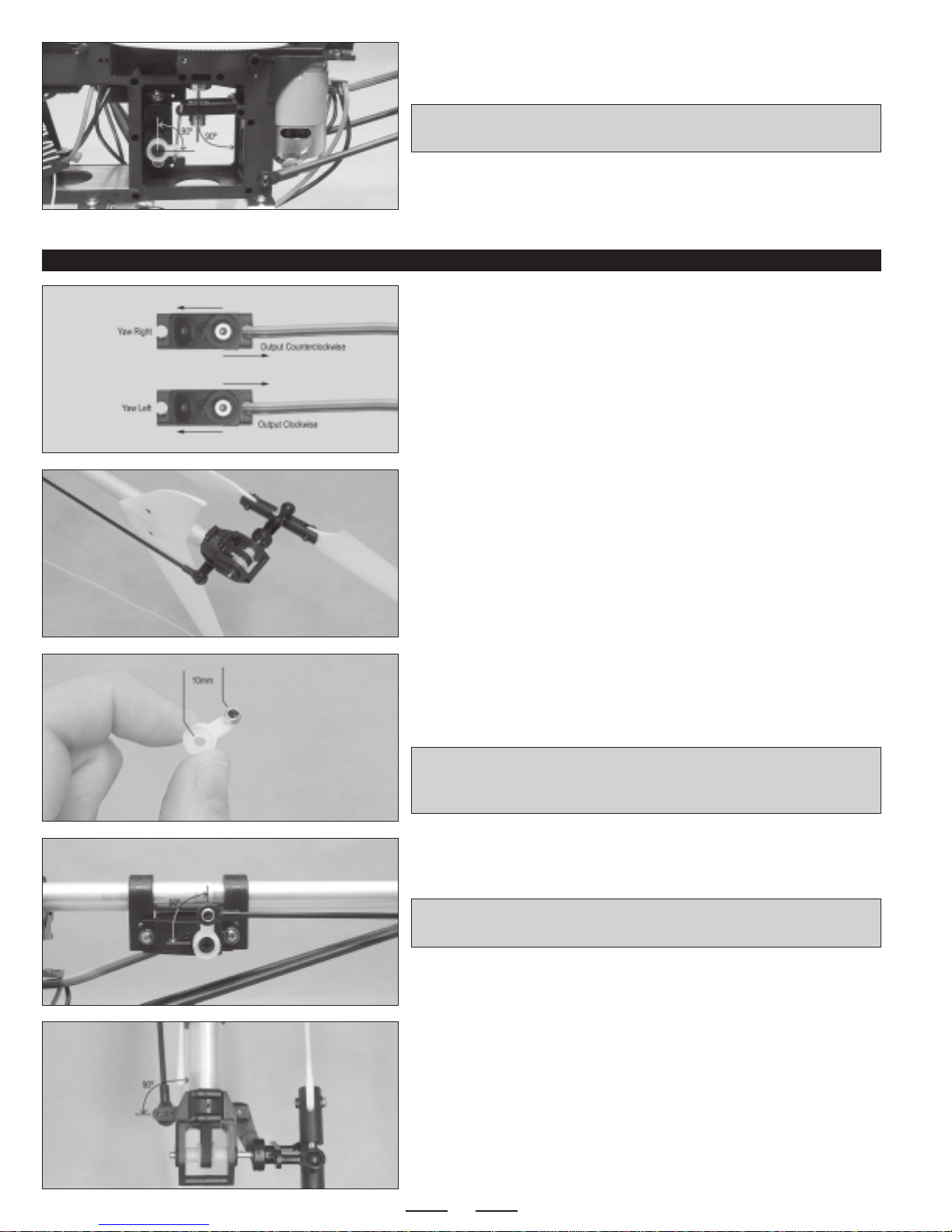
INSTALLING THE COLLECTIVE CONTROL LINKAGE
8
❑Connect the Z-Bend in the collective control wire to your servo arm, then
attach the servo arm to the servo.
✦✦
✦✦
✦IMPORTANT✦✦
✦✦
✦When set up properly, the servo arm should be 90º to
the servo and the collective pitch plate should be 90º to the vertical frame post.
❑Install the servo arm retaining screw, then move the collective up and
down several times to ensure smooth operation.
❑Turn on your radio control system and center the tail rotor servo.
❑Double-check that the tail rotor servo is moving in the correct direction.
When the yaw stick is moved right, the servo output shaft should rotate
counterclockwise.
INSTALLING THE TAIL ROTOR CONTROL LINKAGE
❑Snap one end of the tail rotor pushrod onto the ball-link that's preinstalled
on the tail rotor control arm.
❑Cut away all but one arm from a servo horn.
❑Install one ball-link into the hole that is 10mm out from the center of the
servo horn, using the small screw provided.
✦✦
✦✦
✦IMPORTANT✦✦
✦✦
✦If the hole in your servo arm is too large for the screw to
thread into, you will need to use a machine screw and nut to install the
ball-link to the servo arm.
❑Attach the servo arm to the servo, then snap the end of the tail rotor
pushrod onto the ball-link.
✦✦
✦✦
✦IMPORTANT✦✦
✦✦
✦When set up properly, the servo arm should be 90º to
the servo.
☞You may need to slide the servo mount assembly forward or backward,
so that you can attach the tail rotor pushrod to the ball-link.
❑With the servo arm centered, carefully slide the servo mount assembly
forward or backward until the tail rotor control arm is 90º to the tail boom.
Continued On Next Page ☛☛
☛☛
☛

9
❑When satisfied with the alignment, tighten the two clamp screws firmly to
secure the servo mount assembly into place.
INSTALLING THE ROLL CONTROL LINKAGE
❑Turn on your radio control system and center the roll servo.
❑Double-check that the roll servo is moving in the correct direction.
When the roll stick is moved right, the servo output shaft should rotate
counterclockwise.
❑Cut away all but one arm from a servo horn.
❑Install one ball-link into the hole that is 10mm out from the center of the
servo horn, using the small screw provided.
✦✦
✦✦
✦IMPORTANT✦✦
✦✦
✦If the hole in your servo arm is too large for the screw to
thread into, you will need to use a machine screw and nut to install the
ball-link to the servo arm.
❑Attach the servo arm to the servo, then snap the end of the roll control
pushrod onto the ball-link.
✦✦
✦✦
✦IMPORTANT✦✦
✦✦
✦When set up properly, the servo arm should be 90º to
the servo.
❑Check to ensure that the swashplate is level when viewed from the front.
If it's not, you will need to unsnap the ball-end and thread it in or out to adjust
the length of the control linkage.
INSTALLING THE PITCH CONTROL LINKAGE
❑Turn on your radio control system and center the pitch servo.
❑Double-check that the pitch servo is moving in the correct direction.
When the pitch stick is pulled back, the servo output shaft should rotate
counterclockwise.
Continued On Next Page ☛☛
☛☛
☛

10
❑Cut away all but one arm from a servo horn.
❑Install one ball-link into the hole that is 7mm out from the center of the
servo horn, using the small screw provided.
✦✦
✦✦
✦IMPORTANT✦✦
✦✦
✦If the hole in your servo arm is too large for the screw to
thread into, you will need to use a machine screw and nut to install the
ball-link to the servo arm.
❑Attach the servo arm to the servo, then snap the end of the roll control
pushrod onto the ball-link.
✦✦
✦✦
✦IMPORTANT✦✦
✦✦
✦When set up properly, the servo arm should be 90º to
the servo.
❑Check to ensure that the swashplate is level when viewed from the side.
If it's not, you will need to unsnap the ball-end and thread it in or out to adjust
the length of the control linkage.
INSTALLING THE MAIN ROTOR BLADES
❑Install the main rotor blades, making sure that the rounded leading edge
of both blades is facing the same direction as the rounded leading edge of
the paddles.
✦✦
✦✦
✦IMPORTANT✦✦
✦✦
✦Don't overtighten the socket-cap screws. Tighten them
completely, then back them off about 1/4 - 1/2 of a turn. This will ensure
that the rotor blades are tight, but not binding.
✦✦
✦✦
✦IMPORTANT✦✦
✦✦
✦The rotor blades are balanced from the factory. No balancing is required. The rotor head turns clockwise.
APPLYING THE DECALS AND INSTALLING THE BODY
❑Slide the body over the front of the main frame. To secure it into place,
simply snap the predrilled hole in each side of the body over the matching
pin on the body post on each side of the main frame.
✦✦
✦✦
✦IMPORTANT✦✦
✦✦
✦Double-check that no part of the body interferes with
the main drive gear or the swash plate assembly. If the fit is too close, trim
the body slightly, using a pair of scissors.
❑Carefully cut out and apply the decals to the body and stabilizers, using the box cover photos for reference. If any air bubbles form
under the decals when you apply them you can "prick" the bubbles with a straight pin to release the air.

11
PREFLIGHT SETUP
Before flying your helicopter for the first time, it's important to double-check everything once more and to make sure that you've set the
helicopter up properly for its first few flights.
❑Check the alignment of the tail rotor. With the main rotor blades level,
look from the back of the helicopter at the tail rotor. It should be aligned
perpendicular to the main rotor blades.
☞You can adjust the angle of the tail rotor by loosening the retaining
screw in each side of the tail gear case, then by loosening the two upper
screws that hold the tail gear case halves together. Pivot the tail rotor, and
when satisfied with the alignment, tighten the screws.
❑Double-check the tail rotor belt tension as described on page # 7.
❑Double-check that all of the screws that are used throughout assembly are tight. This includes the small self-tapping screws and the
grub screws, too. All screws should be secured into place, using thread-lock (if threaded into metal) or with a small drop of thin C/A if
threaded into nylon or composite material. This will prevent the screws from loosening during flight.
❑Before each flight you should range-test your radio control system to ensure that it is functioning properly.
❑Double-check that you've installed the servo horn retaining screws in all of the servos.
❑Double-check that the main rotor blade screws and the tail rotor blade screws are snug, but not too tight.
❑Double-check that the paddles are level when all of the controls are centered. Both paddles should be even with each other, too.
❑Balance the helicopter by carefully lifting it up by the flybar with two
fingers, as shown. When balanced properly, the helicopter should hang
level when youlift it. If the nose ofthe helicopter hangs down, move the flight
battery back a little. If the tail of the helicopter hangs down, move the flight
battery forward a little.
❑Double-check that all of the controls are working properly and that they are moving in the correct direction as described below:
Continued On Next Page ☛☛
☛☛
☛
12
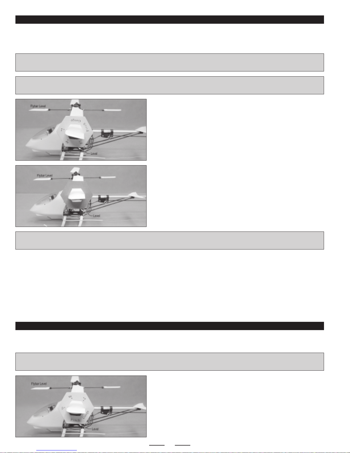
ADJUSTING THE COLLECTIVE PITCH - FOR NEW PILOTS OR NON-3D FLYING
❑Set the recommended amount of collective pitch, using the pitch gauge
included. To begin, slide the pitch gauge onto one main rotor blade, with the
7º mark lined up with the leading edge of the rotor blade. Now, apply full up
collective. Using your transmitter's EPAadjustment, adjust the collective so
that the base of the pitch gauge is parallel to the flybar.
❑Remove the pitch gauge, flip it around so that the printed numbers
are toward the rotor head, and reinstall it so that the 3º mark is lined up
with the trailing edge of the rotor blade. Now, apply full down collective.
Using your transmitter's EPA adjustment, adjust the collective so that the
base of the pitch gauge is parallel to the flybar.
☞You must flip the pitch gauge around so that you can properly set the
negative pitch amount.
If you've never flown the Shogun before, or if you are new to helicopters (gas-powered or electric), or if you will not be using your
Shogun V2 for 3D flight, then we recommend setting the collective pitch as described in this section. We suggest using positive 7º
and negative 3º pitch. This will make the helicopter easier to hover and control throttle.
✦✦
✦✦
✦IMPORTANT✦✦
✦✦
✦Before adjusting the collective, make sure to unplug the motor from the ESC. This will ensure that the motor doesn't
turn on when you make collective adjustments.
✦✦
✦✦
✦IMPORTANT✦✦
✦✦
✦When adjusting the collective as described below, it's not necessary to first zero out the rotor blade pitch angle
with the collective stick centered.
ADJUSTING THE COLLECTIVE PITCH - FOR 3D FLYING
If you're going to be using your Shogun V2 for 3D flying, then we recommend setting the collective pitch as described in this section.
We suggest using positive 7º and negative 7º pitch.
✦✦
✦✦
✦IMPORTANT✦✦
✦✦
✦Before adjusting the collective, make sure to unplug the motor from the ESC. This will ensure that the motor doesn't
turn on when you make collective adjustments.
❑Set the recommended amount of collective pitch, using the pitch gauge
included. To begin, slide the pitch gauge onto one main rotor blade, with the
0º mark lined up with the leading edge of the blade. With the collective
stick centered, the servo arm should be centered and the base of the pitch
gauge should be parallel to the flybar, indicating 0º pitch. If necessary, use
your transmitter to adjust the collective to 0º. You can also adjust the
linkages mechanically.
Continued On Next Page ☛☛
☛☛
☛
✦✦
✦✦
✦IMPORTANT✦✦
✦✦
✦Using this setup method, the blades will not have 0º pitch when the collective stick is centered. 0º pitch will occur at
approximately 1/3rd collective stick. This will result in the helicopter being easier to hover and control the throttle.
❑We recommend between 75% and 100% throttle hold, so that you can switch the throttle to a fixed position by pressing the throttle
hold switch on your transmitter. This allows the collective to work independently of the throttle.
❑We use only standard collective/throttle mixing. If you would like to experiment with a linear throttle curve, linear pitch curve and/or
revolution mixing, we recommended doing so only a little at a time, until you are satisfied with the results.

13
❑Remove the pitch gauge and reinstall it so that the 7º mark is lined up
with the leading edge of the rotor blade. Now, apply full up collective. Using
your transmitter's EPA adjustment, adjust the collective so that the base of
the pitch gauge is parallel to the flybar.
❑Repeat the procedure above for full down collective. When set up
properly, you should have 7º of collective pitch in each direction.
❑We recommend between 75% and 100% throttle hold, so that you can switch the throttle to a fixed position by pressing the throttle
hold switch on your transmitter. This allows the collective to work independently of the throttle.
❑We use only standard collective/throttle mixing. If you would like to experiment with a linear throttle curve, linear pitch curve and/or
revolution mixing, we recommended doing so only a little at a time, until you are satisfied with the results.
ADJUSTING THE MAIN ROTOR BLADE'S ROTATIONAL PLANE
❑Put a 1/2" square piece of colored tape over the leading edge of one
main rotor blade.
❑Smoothly open the throttle until the heli begins to lift off and watch the
rotational plane of the rotor blades. The rotational plane of both rotor blades
should be the same. If they are not, adjustments need to be made.
✦✦
✦✦
✦IMPORTANT✦✦
✦✦
✦When spinning, both blades should be even with each
other. They should not appear to waver or oscillate up and down.
❑Check the correct operation of your gyro. While holding the helicopter, quickly pivot the tail counterclockwise and observe the
movement of the tail rotor servo arm. If your gyro is lined up properly, the servo arm should move counterclockwise. If the servo arm
moves clockwise, you'll need to mount your gyro in the opposite direction.
❑To adjust the rotational plane, disconnect the ball-end from the blade
with the higher rotational plane and tighten the ball-end 1 full turn.
❑Reconnect the ball-end and test the rotational plane of the rotor blades
again. Repeat the procedure until satisfied with the alignment.
CHECKING GYRO OPERATING DIRECTION
❑Remove the pitch gauge, flip it around so that the printed numbers
are toward the rotor head, and reinstall it so that the 7º mark is lined up
with the trailing edge of the rotor blade. Now, apply full down collective.
Using your transmitter's EPA adjustment, adjust the collective so that the
base of the pitch gauge is parallel to the flybar.
☞You must flip the pitch gauge around so that you can properly set the
negative pitch amount.
3D ASSEMBLY DRAWINGS, REPLACEMENT PARTS AND HOP-UP PARTS
CAN BE FOUND BEGINNING ON THE NEXT PAGE

14
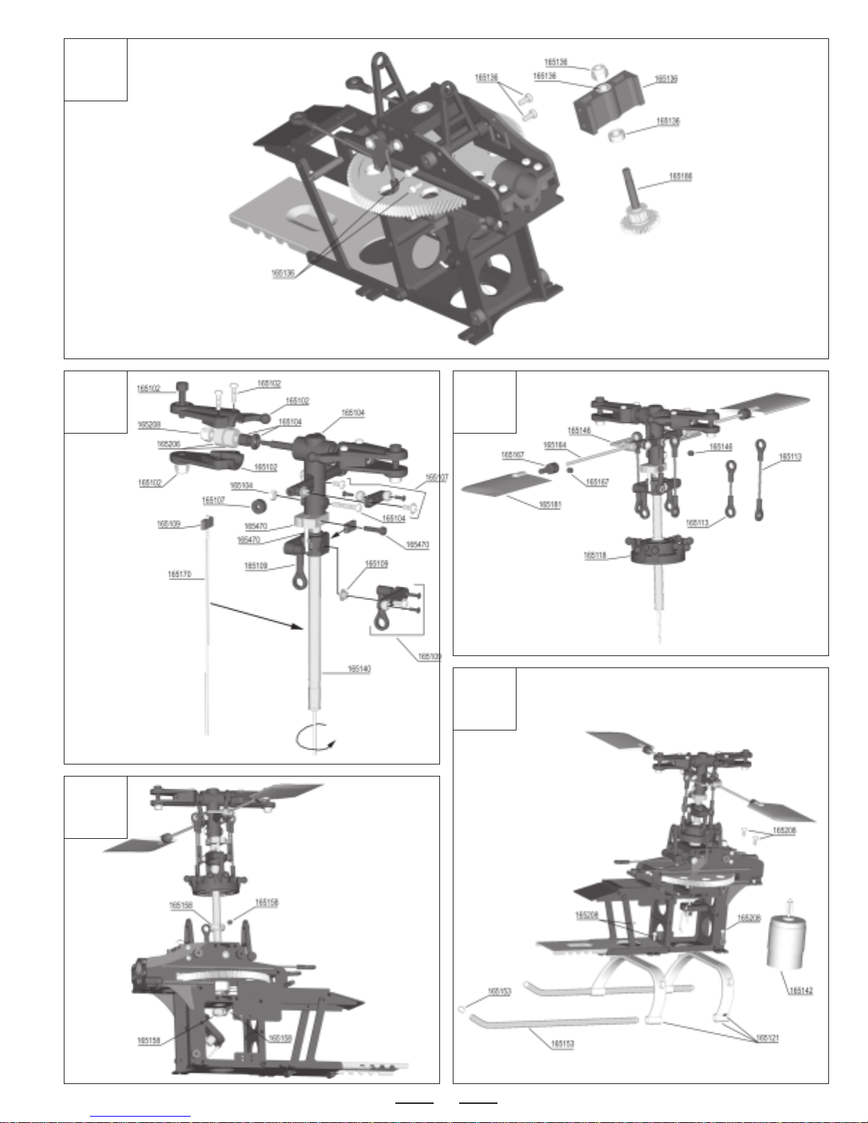
3D ASSEMBLY DRAWINGS
1
2
3
Continued On Next Page ☛☛
☛☛
☛
15
4
5 6
7
8
Continued On Next Page ☛☛
☛☛
☛
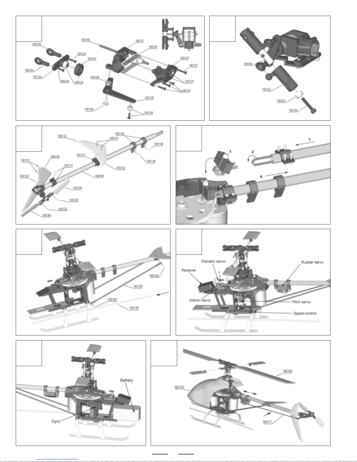
16
910
11 12
13
15
14
16

17
17 18
1
4
3
5
2
As an option, you can install the bevel gear tail rotor drive mechanism into your Shogun 400 V2 helicopter. To do this, you will need the
following parts:
●165161 Carbon Tail Rotor Drive Shaft with Bevel Gear
●165189 Tail Drive Input Gear (Bevel)
●165192 Tail Output Shaft - Round (Bevel)
●165205 Shaft Bearings for V2 Tail Boom and Solid Drive Shaft
OPTIONAL BEVEL GEAR TAIL ROTOR DRIVE INSTALLATION
Slide the non-flanged bearing into the middle of the
tail boom, then install the two flanged bearings into
each end of the tail boom.
Use a punch and a small hammer
to make a punch mark in the tail
boom to secure the center
bearing in place.
Slide the drive shaft into the tail boom, then secure
the bevel gear to the front of the drive shaft, using a
grub screw. Make sure to tighten the grub screw
against the flat spot on the drive shaft.
Install the tail rotor and tail output shaft assembly, then install the gear
case onto the tail boom, making sure that the tail output shaft and drive
shaft gears line up correctly.
Secure the tail boom assembly to the main frame, making sure that the
pinion and tail boom gears line up correctly. Move the tail boom assembly
in or out slightly to adjust the gear mesh. When set properly, the gear-
train should rotate smoothly with only a slight amount of backlash.
18
Westock a complete set of replacementpartsforyour Shogun 400 V2 helicopter. Listed below are thereplacement parts thatare available
along with their respective part numbers for easy ordering convenience. We suggest ordering directly from your local dealer.
If your dealer does not stock EF Helicopters products, you can order replacement parts
directly from us, using the Customer Service Information on page # 2.
REPLACEMENT PARTS
165099
Instruction Manual 165103
Main Frame Set 165102
Main Rotor Grip Set 165104
Main Rotor Yoke
165107
See-Saw Set 165109
Washout Base Set 165111
Elevator Crank Set 165113
Ball-End Control Rod Set
165115
Aileron Lever Set 165116
Pitch Lever Joint Set 165118
Swash Plate Assembly 165121
Landing Gear Brace Set
165122
Tail Rotor Grip Set 165124
Tail Pitch Yoke 165127
Tail Gear Case Set 165129
Tail Pitch Control Lever Set
H002 H003H001V2
H004V H005V H006V H007V
H008V H009 H010 H011V
H012 H013 H014V2 H015V
165131
Tail Boom Support Clamp Set 165132
Stabilizer and Fin Set 165136
Belt Gear Mount Set 165138
Rudder Servo Mount Set
H016V2 H017 H018V2 H019V2
Continued On Next Page ☛☛
☛☛
☛
HOP-UP AND OPTION PARTS ARE SHOWN BEGINNING ON PAGE # 20

19
165139
Antenna Support Tube 165133
Body and Canopy Set 165140
Main Shaft (Mast) 165142
380 Motor with Pinion Gear
165143
Motor Pinion Gear 165144
Spindle Shaft 165146
Stabilizer Arm Set 165149
Tail Boom (with Bearing)
165150
Tail Boom Support Set 165153
Landing Gear Set 165154
Tail Rotor Hub Set 165156
Auto-Rotation Sleeve Set
165158
Main Shaft Stopper Set 165160
HP Main Shaft (Mast) 165164
Flybar 165167
Flybar Adapter Set
165170
Collective Pitch Rod 165171
Rudder Pushrod 165180
Main Rotor Blade Set 165181
Stabilizer Blade Set (Paddles)
165184
Tail Rotor Blade Set 165185
Tail Output Shaft Set 165196
Main Gear 165186
Belt Gear Shaft
H020V2 H100V2 M001 M002
M002G M003 M004 M005V2
M006V M007V M008 M009
M010 M011 M013
M016
M014V
M020V2 P101 P201
P301 G011V2 G281V2G132
REPLACEMENT PARTS, CONTINUED....
Continued On Next Page ☛☛
☛☛
☛

20
165187
Tail Rotor Belt 165200
One-Way Bearing 165202
Ball Bearing (2x5x2.5L) 165206
Ball Bearing (3x8x4L)
165208
Screw Set 165332
Battery Mount 165178
O-Rings for Spindle Shaft
G371V2 B252
S001 O802
REPLACEMENT PARTS, CONTINUED....
B106 B384
165302
CF Tail Boom 165308
CF Main Frame Set 165301
Gyro Tail Mount 165329
CF Main Frame Reinforcement
165331
CF Pitch Lever Joint Set 165322
CF Main Blade Set 165330
CF Stabilizer Blades (Paddles) 165334
CF Tail Rotor Blades
O005V2 O006V2 O012
O102 O202
HOP-UP AND OPTION PARTS
O010V2
O013 O302
Continued On Next Page ☛☛
☛☛
☛
165098
Decal Set
Sorry, No
PhotoAvailable
P000
165470
Alum Main Rotor Yoke
O503
Table of contents
Other EF Helicopter Toy manuals


Popular Toy manuals by other brands

LEGO
LEGO Cars 2 8677 Assembly guide

Mattel
Mattel Barbie X9057 instructions

Hasbro
Hasbro Shrek 2 Far, Far Away Castle instructions

LEGO
LEGO Alien Conquest 7065 Building instructions

Bandits and Angels
Bandits and Angels TWT8033 Assembly instructions

Eduard
Eduard Zoom F-18E Super Hornet interior quick start guide


Skywalker
Skywalker X-8 Assembly manual

Eduard
Eduard Fw 109A-8/R11 Assembly instructions

Rompa
Rompa SNORING PIG manual

Fisher-Price
Fisher-Price LittlePeople L2344 quick start guide

Dancing Wings Hobby
Dancing Wings Hobby Pitts 450mm instruction manual

Little Tikes
Little Tikes Little Baby Bum 3-in-1 Music Bus quick guide