Efka AB323A5221 Instruction manual

CONTROL AB323A5221
LIST OF PARAMETERS
CONNECTION DIAGRAM
TIMING DIAGRAMS
No. 402309 English
FRANKL & KIRCHNER EFKA OF AMERICA INC. EFKA ELECTRONIC MOTORS
GMBH & CO KG SINGAPORE PTE. LTD.
>>
+
P
E
-
I
0
KL2334a

EFKA AB323A5221
3
CONTENTS Page
1 Putting into Service 5
2 Operating Elements and Socket Connectors 6
2.1 Position of Operating Elements and Displays 6
2.2 Position of the Socket Connectors 6
2.3 Connection Diagram 7
2.4 Connection of a Sewing Light with Transformer 11
3 Timing Diagrams 12
4 List of Parameters 16
4.1 Preset Values Depending on Mode 16
4.2 Operator Level 18
4.3 Technician Level 19
4.4 Supplier Level 21
5 Error Displays 26
6 Operating Elements of the V810 Control Panel 27

EFKA AB323A5221
5
1 Putting into Service
Before putting the control into service, the following must be ensured, checked and/or adjusted:
§ The correct installation of the drive, position transmitter and accompanying devices, if necessary
§ If necessary, the correct adjustment of the direction of motor rotation by means of parameter 161
§ The correct selection of the functions of keys (inputs) by means of parameters 240...249
§ The setting of the transmission ratio between motor shaft and machine shaft by means of parameter 272
§ The setting of the type of position sensor by means of parameter 270
§ If necessary, the setting of the number of angular degrees after the sensor position by means of parameter 271
§ If necessary, the setting of the positions by means of parameter 171
(possible with all settings of parameter 270)
§ The correct positioning speed by means of parameter 110
§ The correct maximum speed compatible with the sewing machine by means of parameter 111
§ The setting of the remaining relevant parameters
§ Start sewing in order to save the set values
See instruction manual for details!

EFKA AB323A5221 6
2 Operating Elements and Socket Connectors
2.1 Position of Operating Elements and Displays
S1 P key
§ Call or exit programming mode
S2 E key
§ Foot lifting pressure or puller in StartCycle On / Off
§ Enter key for modifications in the programming mode
S3 + key
§ JointSystem On / Off
§ Increase of the value indicated in the programming mode
S4 – key
§ Puller with pedal in pos –2 On/Off
§ Decrease of the value indicated in the programming mode
S5 >> key
§ Basic position 1 or 2
§ Shift key in the programming mode
LED1 Foot lifting pressure in StartCycle On / Off
LED2 Puller in StartCycle On / Off
LED3 JointSystem On / Off
LED4 No function
LED5 Puller with pedal in pos –2 On/Off
LED6 No function
LED7 Indicator for basic position “needle position 1“
LED8 Indicator for basic position “needle position 2“
Display 3 digits
2.2 Position of the Socket Connectors
B2 Socket for commutation transmitter
B18 Socket for - Light barrier module LSM002
- Hall sensor module HSM001
- Pulse encoder IPG001
- EFKANET
(Adapter cord 1113229 in case of multiple assignment)
B41 Socket for motor power supply
B80 Socket for actuator
B776 Socket for V810/V820 control panel
ST2 Socket for solenoid inputs and outputs /
solenoid valves / displays / keys and switches
LED4
LED5
LED6
LED7
LED8
Display
LED1
LED2
LED3
-2
+
-
P
E
S4
S5
S1
S2
S3
0
I
KL2535
M
B41
B18
KL2333
ST2
B2
B41
B2
LSM...
M
B18
IPG...
HSM...
B776
A
Adapter 1113229
LSM...+ HSM...
LSM...+ IPG...
ST2
V8 . .
B80
EB...
B776
B80

EFKA AB323A5221
7
2.3 Connection Diagram
Inputs switched to 0V Parameter 290 = 1
in1 - Input 1 (JointSystem) i10 - Input 10 M9 - Output 9 (sewing foot pressure)
in2 - Input 2 M1 - Output 1 M10 - Output 10 (Step-Out)
in3 - Input 3 M2 - Output 2 M11 - Output 11 (vacuum suction)
in4 - Input 4 M3 - Output 3 FL - Sewing foot lifting
in5 - Input 5 M4 - Output 4 VR - Backtacking
in6 - Input 6 M5 - Output 5 (motor running) POS1 - Position 1
in7 - Input 7 M6 - Output 6 POS2 - Position 2
in8 - Input 8 M7 - Output 7 (puller) GEN - 512 generator impulses
in9 - Input 9 M8 - Output 8 (needle cooling) R-N-EXT - External potentiometer for
speed limitation (50kΩ)
A
TTENTION!
When connecting the outputs, ensure that a total power of 96VA constant load will not
be exceeded!

EFKA AB323A5221 8
Inputs switched to 0V Parameter 290 = 2
in1 - Input 1 (sensor 1) i10 - Input 10 M9 - Output 9
in2 - Input 2 (sensor 2) M1 - Output 1 (knife) M10 - Output 10 (Step-Out)
in3 - Input 3 (ext. key 1) M2 - Output 2 M11 - Output 11
in4 - Input 4 (ext. key 2) M3 - Output 3 (SkipSpreader) FL - Sewing foot lifting
in5 - Input 5 (ext. key 3) M4 - Output 4 (lift stop guide) VR - Backtacking
in6 - Input 6 (ext. key 4) M5 - Output 5 (motor running) POS1 - Position 1
in7 - Input 7 (ext. key 5) M6 - Output 6 (puller 2) POS2 - Position 2
in8 - Input 8 M7 - Output 7 (puller 1) GEN - 512 generator impulses
in9 - Input 9 M8 - Output 8 (needle cooling) R-N-EXT - External potentiometer for
speed limitation (50kΩ)
A
TTENTION!
When connecting the outputs, ensure that a total power of 96VA constant load will not
be exceeded!

EFKA AB323A5221
9
Inputs switched to +24V
1) Nominal voltage 24V, no-load voltage max. 30V momentarily after power on
2) Transistor output with open collector max. 40V, 10mA
3) Nominal voltage 15V, Imax = 30mA
4) Nominal voltage 5V, Imax = 20mA
*) Front view of the socket (component side) and/or rear view of the plug (soldering side)
A
TTENTION!
When connecting the outputs, ensure that a total power of 96VA constant load will not
be exceeded!

EFKA AB323A5221 10
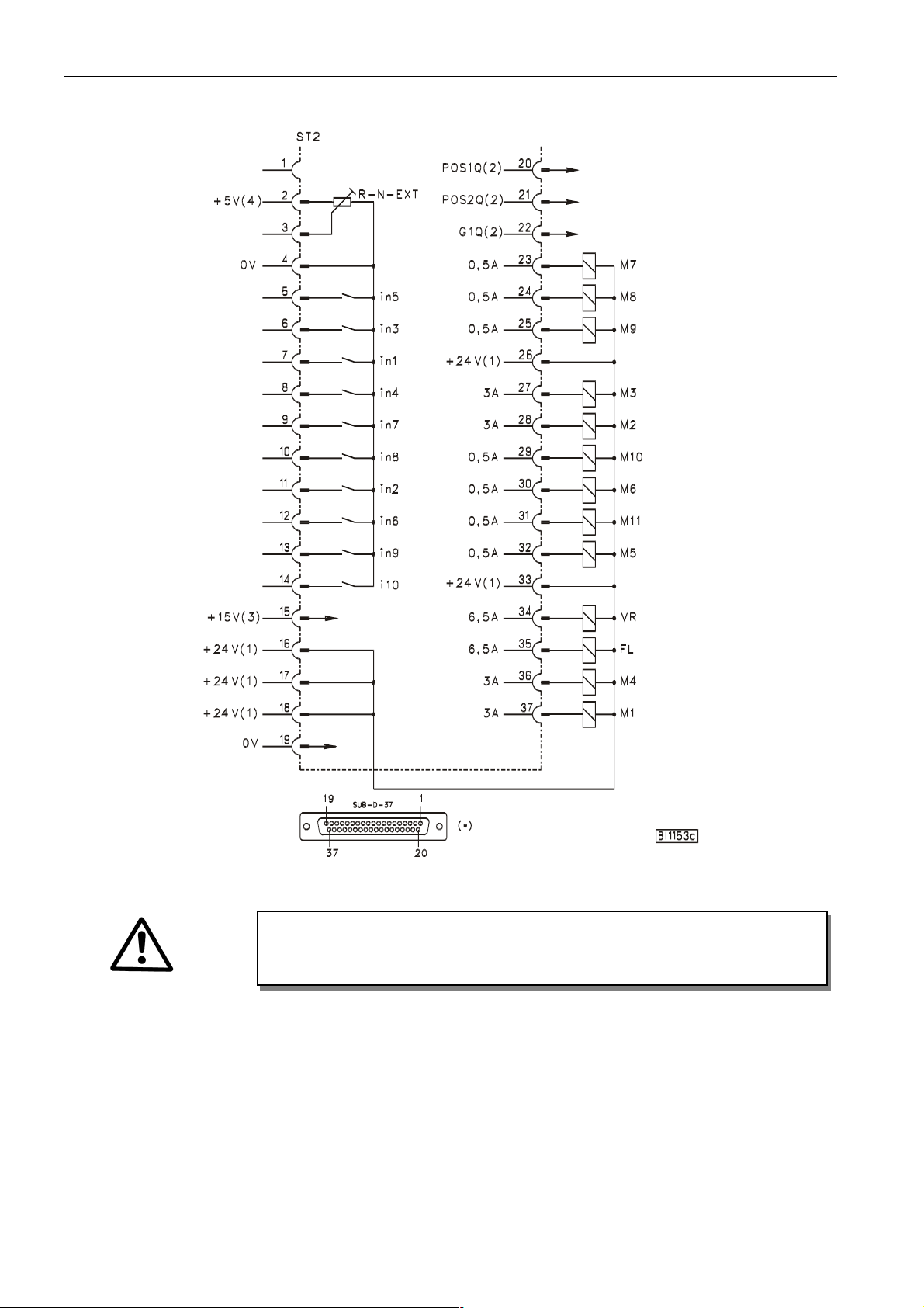
Connection of a HSM001 Hall sensor module Connection of a LSM002 light barrier module
or an IPG001 pulse encoder
Adapter cord 1113229 in case of multiple assignment of socket B18!
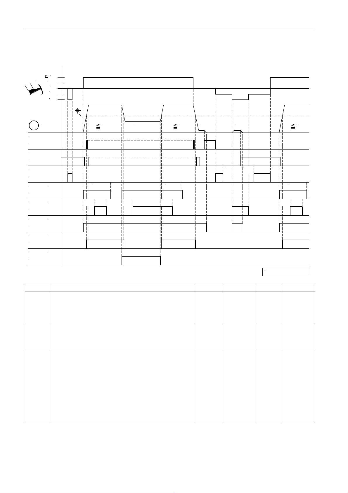
POS2 OUT - Output for position 2
POS IN - Input for positions
G1/G2 OUT - Output of generator impulses
TXD/RXD - Serial transmission lines
LSM IN - Possibility of connecting a light barrier module to socket B18/8
(If parameter 239 = 0, the light barrier function is selected.
Identification of the signal when switched to 0V.)
LSM002 - Reflection light barrier module
HSM... - Hall sensor module
IPG... - Pulse encoder
If parameter 239 is set to >0, a key can be operated on the input of socket B18/8.
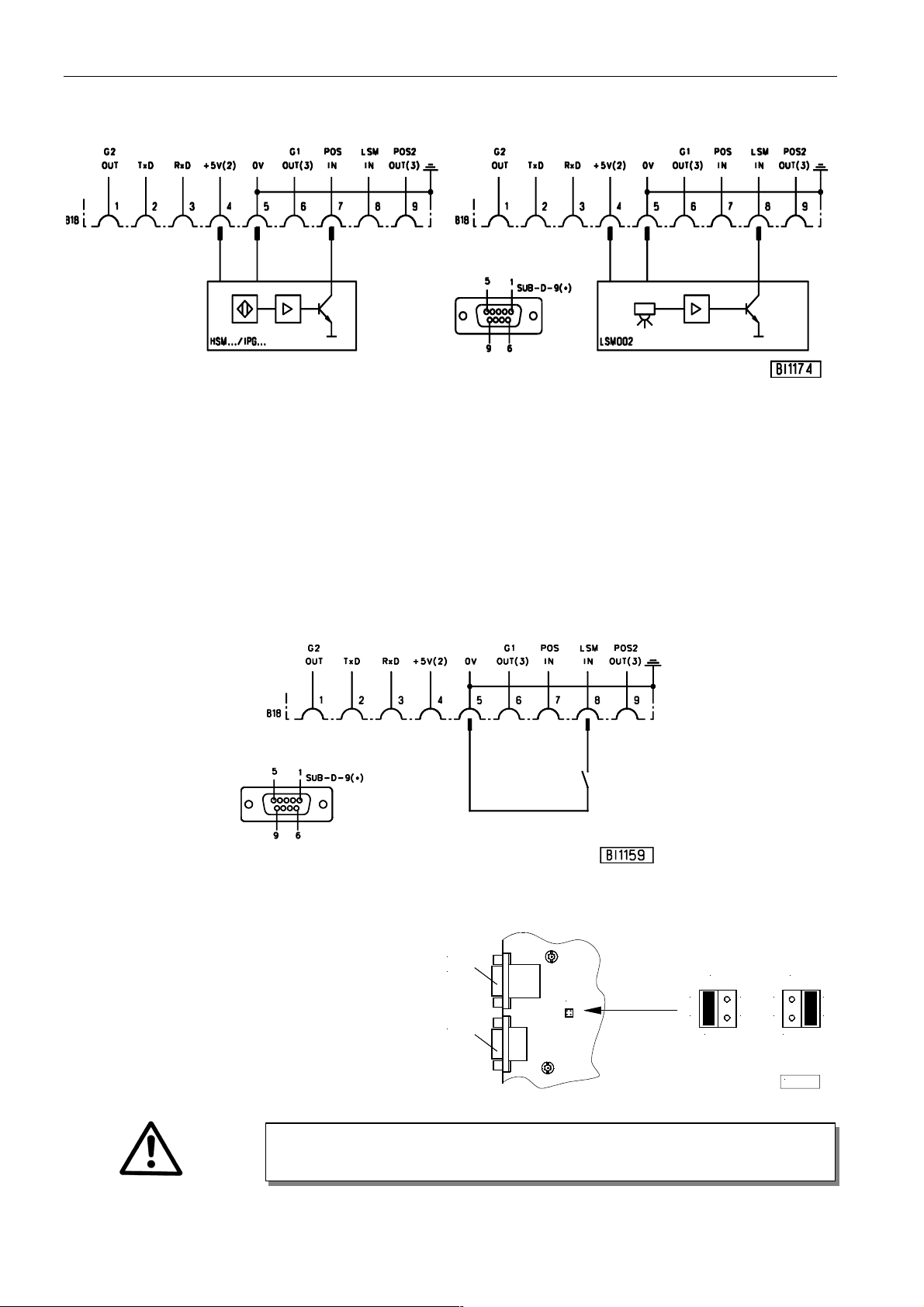
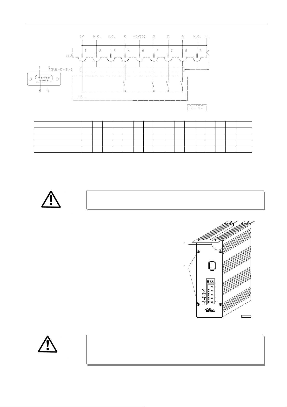
There is a supply voltage of +5V for external devices on the B18/4 socket. After opening the cover, this voltage can be
changed to +15V by replugging a multipole connector J1 on the printed circuit board.
+5V = Connect lefthand pins 1 and 2 with jumper
(factory setting)
+15V = Connect righthand pins 3 and 4 with jumper
1) Nominal voltage +15V, 100mA (repluggable to +5V, 100mA)
2) Transistor output with open collector max. 40V, 10mA
*) Front view of the socket (component side) and/or rear view of the plug (soldering side)
A
TTENTION!
Before opening the cover, turn power off!
B80
B18
B2
J4 31
+5V
42
J4
1 3
4
+15V
2
KL2351
J4

EFKA AB323A5221
11
EB.. Actuator
Pedal step è
èè
è-2 -1 0 ½ 1 2 3 4 5 6 7 8 9 10 11 12
Input A L L H H H L L H H L L H H L L H
Input B L H H L L L H H H H L L L L H H
Input C H H H H L L L L L L L L H H H H
Input D H H H H H H H H L L L L L L L L
2.4 Connection of a Sewing Light with Transformer
§ Switch off the control and remove mains plug from outlet
§ Unscrew the control unit from the machine table
§ Loosen 2 screws (A) each at the front and at the rear
§ Open the left part of the housing
§ Pull the sewing light cable through the cable bushing
§ Area (B): Connect strands with clamp on the printed circuit board
§ Insert earth lead into plug-in device on the housing part
§ Close and screw-connect the housing
§ Mount the control unit on the machine table
CAUTION!
When the sewing light is connected, it is always current-carrying (230V), even if
the control unit is switched off! Only one sewing light with transformer can be
connected to the control unit!
A
TTENTION!
Before opening the cover, turn power off!
>>
E
-
+
P
A
B
0
I
KL2399a

EFKA AB323A5221 12
3 Timing Diagrams
Function for mode 1 (parameter 290 = 1)
ds6
ds4
ST2/21
ST2/25
PUL
ST2/23
ST2/32
ST2/35
FLD
SEN
ST2/7
ST2/24
AS
NK
FL
(M5)
(in1)
(M8)
(M7)
(M9)
-
POS.2
POS.1
ST2/20
-2
n
+
1/2
1
0
-1
ds5ds3
ds1
ds2
n2 n10
t3 kdF
n2 n1 n1
ds1
ds3
0284/MODE-1a
ds2
t3
n2
Mark Function Parameter Control V810 V820
Fam Mode 1 290 = 1
Foot lift pressure and puller in StartCycle On E key 1 key 1 key
JointSystem On/Off + key 2 key 2 key
Puller with pedal in pos. –2 On/Off - key 3 key 3 key
Basic position down >> key 4 key 4 key
n1 Positioning speed 110
n2 Maximum speed 111
n10 High lift walking speed 117
n9 *) Triggering speed for needle cooling 122
ds1 Feeding section for sewing foot pressure at the start of the 001
seam
ds2 Feeding section for puller delayed at the start of the seam 002
On
ds3 Feeding section for puller lifting at the start of the seam On 003
ds4 Feeding section for delayed sewing foot pressure Off 004
ds5 Feeding section for delayed puller lifting On 005
ds6 Feeding section for puller On 006
t3 Start delay from lifted sewing foot 202
t4 Full power of sewing foot lifting 203
t5 Pulsing of sewing foot lifting 204
kdF Switch-on delay of sewing foot lifting 288
Explanation of further letter symbols:
POS.1 = Position 1 (needle down) AS = Signal for suction
POS.2 = Position 2 (needle up) NK = Signal for needle cooling
FL = Signal for sewing foot lifting SEN = Sensor for JointSystem
FLD = Signal for sewing foot pressure ds1...ds6 = Unit in mm
PUL = Signal for puller lifting

EFKA AB323A5221
13
Function for mode 1 (parameter 290 = 1)
Setting the Stitch Length
d
ST2/21
STL
POS.3
ST2/29
(mm)
POS.2
POS.1
ST2/20
1E
REF
-
POS
.
StL
3E
StL
360°
1A
2E 2A
StL
0284/MODE-1b
Mark Function Parameter
Fam Mode 1 290 = 1
StL Stitch length in mm (1mm = 20 impulses for puller motor) 000
REF-POS. Reference position 170
1E Position 1 (leading edge) 171
1A Position 1 (trailing edge) 171
2E Position 2 (leading edge) 171
2A Position 2 (trailing edge) 171
3E dStL Position 3 (leading edge) 455

EFKA AB323A5221 14
Function for mode 2 (parameter 290 = 2)
Pneumatic operation
ST2/21
ST2/35
ST2/7
ST2/11
ST2/27
ST2/37
PL2
ST2/30
SEN 1
SEN 2
FL
KN
SS
(in1)
(in2)
(M1)
(M6)
(M3) ds4
-
POS.2
POS.1
ST2/20
-2
n
+
1/2
1
0
-1
d12-
d11
ds3
kt1
n10
ds2
d12+
d14-d13
kt1
ds3
n2 n10 n2
0284/MODE-2a
kdF
n1
Mark Function Parameter Control ext. key strip
FAm Mode 2 290 = 2
SmP Pneumatic operation 040 = 2
Manual material feed using puller 1 with Key 1
needle up and lifted sewing foot
Cutting + spreader function Off / Skip stitch function On Key 2
Spreader function On/Off Key 3
Manual trimmer (cutting) Key 4
Lift/lower puller Key 5
n1 Positioning speed 110
n2 Maximum speed 111
n10 High lift walking speed 117
ds2 Distance from sensor 2 uncovered to knife On 002
ds3 Activation of puller lifting after autom. trimming 003
ds4 Distance from sensor 1 covered to spreader Off 004
d11 Waistband up to trimming at the start 011
d12 Distance from sensor 2 to knife 012
d13 Skip stitch at the end 013
d14 Offset for skip stitch 014
kt1 Knife ON period 281
kdF Switch-on delay of sewing foot lift 288
The basic position is controlled using sensor 1. If the sensor is covered, the drive stops in position 1. Otherwise the drive
stops in position 2.
Explanation of further letter symbols:
OS.1 = Position 1 (needle down) POS.2 = Position 2 (needle up) FL = Signal for sewing foot lift
SS = Signal for SkipSpreader KN = Signal for knife PL2 = Signal for “lift puller 2”
SEN1 = Input for sensor 1 SEN2 = Input for sensor 2 ds2...d14 = Unit in mm

EFKA AB323A5221
15
Function for mode 2 (parameter 290 = 2)
Motor operation
ST2/21
ST2/35
ST2/7
ST2/11
ST2/27
ST2/37
PL2
ST2/30
MOT
SEN 1
SEN 2
KN
FL
SS
(M1)
(in1)
(M6)
(in2)
(M3)
-
POS.2
POS.1
ST2/20
-2
n
+
1/2
1
0
-1
d11
ds3
kt1d12-
n10
0284/MODE-2b
kt1
dFw
ds7
ds2
t5t4
d12+
d10
n2 n1
ds3
n10
Mark Function Parameter Control ext. key strip
FAm Mode 2 290 = 2
SmP Motor operation 040 = 1
Manual material feed using puller 1 with Key 1
needle up and lifted sewing foot
Cutting + spreader function Off / Skip stitch function On Key 2
Spreader function On/Off Key 3
Manual trimmer (cutting) Key 4
Lift/lower puller Key 5
n1 Positioning speed 110
n2 Maximum speed 111
n10 High lift walking speed 117
ds2 Distance from sensor 2 uncovered to knife On 002
ds3 Activation of puller lifting after autom. trimming 003
ds7 Distance from sensor 1 uncovered to stop in position 2 007
d10 Material feed after stop (motor operation) 010
d11 Waistband up to trimming at the start 011
d12 Distance from sensor 2 to knife 012
d13 Skip stitch at the end 013
d14 Offset for skip stitch 014
t3 Start delay from lifted sewing foot 202
t4 Full power of sewing foot lifting 203
t5 Pulsing of sewing foot lifting 204
dFw Delay time from stop in position 2 to puller motor On 209
kt1 Knife ON period 281
The basic position is controlled using sensor 1. If the sensor is covered, the drive stops in position 1. Otherwise the drive
stops in position 2.
Explanation of further letter symbols:
OS.1 = Position 1 (needle down) POS.2 = Position 2 (needle up) FL = Signal for sewing foot lift
SS = Signal for SkipSpreader KN = Signal for knife PL2 = Signal for “lift puller 2”
SEN1 = Input for sensor 1 SEN2 = Input for sensor 2 ds2...d14 = Unit in mm
MOT = Stepping motor

EFKA AB323A5221 16
4 List of Parameters
4.1 Preset Values Depending on Mode
All preset values of the different modes are listed in the table below. The parameters marked with “---“ are not available
and cannot be called up. When switching the mode by means of parameter 290, all values change automatically.
Operator Level
Setting the functional sequence using parameter 290
Parameter Letter symbol Mode 1 Mode 2
000 StL 3.2 3.2
001 dS1 20.0 9.0
002 dS2 15.0 2.0
003 dS3 15.0 3.0
004 dS4 30.0 5.0
005 dS5 15.0 2.0
006 dS6 15.0 3.0
007 dS7 15.0 3.0
008 dS8 --- 15.0
009 dS9 --- 50.0
010 d10 --- 50.0
011 d11 --- 20.0
012 d12 --- 50.0
013 d13 --- 20.0
014 d14 --- 50.0
015 d15 30.0 ---
016 d16 --- 0
017 d17 --- 0
018 t18 0 0
040 SmP --- 1
041 m2P --- 1
Technician Level
Setting the functional sequence using parameter 290
Parameter Letter symbol Mode 1 Mode 2
100 SSc 2 2
110 ** n1 200 200
111 ** n2- 4000 4000
115 ** n6 500 500
117 ** n10 1000 1000
119 nSt 2 2
121 ** n2_ 400 400
122 ** n9 2000 2000
139 nIS 0 0
153 brt 10 10
155 LSG 1 1
156 t05 0 0
161 der 1 1
**) When programming the 3-digit or 4-digit control parameter values (without control panel), the 2-digit or 3-digit
value displayed must be multiplied by 10.

EFKA AB323A5221
17
Supplier Level
Setting the functional sequence using parameter 290
Parameter Letter symbol Mode 1 Mode 2
201 t2 80 80
202 t3 50 50
203 t4 500 500
204 t5 40 40
207 br1 20 20
208 br2 30 30
209 dFw 0 0
211 tFL 60 60
214 rAt 80 80
215 ** FrG --- 2000
216 ASt --- 0
219 br3 10 10
220 ALF 20 20
221 ** dGn 100 100
222 tGn 120 120
223 ** dG2 1600 1600
224 dGF 1 1
225 br4 27 27
231 Sn1 0 0
236 FLP 0 0
238 EnP 1 1
239 FEL 0 0
240 in1 56 59
241 in2 58 60
242 in3 0 0
243 in4 0 0
244 in5 0 0
245 in6 0 0
246 in7 0 0
247 in8 0 0
248 in9 0 0
249 i10 0 0
254 EF- 100 100
269 PSv 15 15
270 PGm 0 0
272 trr 100 100
281 kt1 --- 100
288 kdF 380 380
290 Fam 1 2
291 810 1 ---
293 tF1 0 0
294 tF2 0 0
295 nAm 0 0
297 m11 0 0
455 120 120
**) When programming the 3-digit or 4-digit control parameter values (without control panel), the 2-digit or 3-digit
value displayed must be multiplied by 10.

EFKA AB323A5221 18
4.2 Operator Level
Parameter Designation Unit max min Preset Ind.
Pa. 290 = 1, 2
000 StL Stitch length by means of external puller motor mm 50.0 0 *) A
Pa. 290 = 1
001 dS1 Activation of sewing foot pressure signal at the mm 50.0 0 *) A
start of the seam (StartCycle)
Pa. 290 = 1
002 dS2 Delay until puller lifitng at the start of the seam mm 50.0 0 *) A
(StartCycle)
Pa. 290 = 2
Distance ds2 sensor 2 uncovered to knife On
Pa. 290 = 1
003 dS3 Activation of puller lifting at the start of the seam mm 200.0 0 *) B
(StartCycle)
Pa. 290 = 2
Activation of puller lifting after automatic
trimming
Pa. 290 = 1
004 dS4 Switch-off delay for sewing foot pressure mm 50.0 0 *) A
(JointSystem)
Distance ds4 sensor 1 covered to spreader Off
(closed)
Pa. 290 = 1
005 dS5 Delay until puller lifting (JointSystem) mm 50.0 0 *) A
Pa. 290 = 1
006 dS6 Delay until puller lowering (JointSystem) mm 50.0 0 *) A
Pa. 290 = 1
007 dS7 Delay until signal M11 Off mm 50.0 0 *) A
(vacuum suction)
Pa. 290 = 2
Distance ds7 sensor 1 uncovered to stop in
position 2
Pa. 290 = 2
008 dS8 Delay until puller 2 lowers mm 50.0 0 *) B
Pa. 290 = 2
009 dS9 Material feed during preparation mm 100.0 0 *) B
(motor operation)
Pa. 290 = 2
010 d10 Material feed after stop mm 100.0 0 *) B
(motor operation)
Pa. 290 = 2
011 d11 Waistband up to trimming at the start mm Pa.012 0 *) B
Pa. 290 = 2
012 d12 Distance from sensor 2 to knife mm 100.0 Pa.011 *) B
Pa. 290 = 2
013 d13 Skip stitch at the end mm Pa.014 0 *) B
Pa. 290 = 2
014 d14 Offset for skip stitch mm 100.0 Pa.013 *) B
Pa. 290 = 1
015 d15 Delay speed release in JointSystem min 100.0 0 *) B
Pa. 290 = 2
016 d16 Debouncing for sensor 1 mm 100.0 0 *) B
Pa. 290 = 2
017 d17 Debouncing for sensor 2 mm 100.0 0 *) B
018 t18 Switch-off delay for needle cooling after stop sec 60.0 0 *) B
040 SmP Switch motor / pneumatic 2 1 *) B
1 = motor operation
2 = pneumatic operation
041 m2P Funcion for 2nd puller 2 1 *) B
*) See table at the beginning of the Parameter List for preset values!

EFKA AB323A5221
19
4.3 Technician Level
Code no. 190 with control operation
Code no. 1907 with control panel operation
Parameter Designation Unit max min Preset Ind.
100 SSc Number of softstart stitches stitches 254 0 *) A
110 n1 Positioning speed RPM 390 **) 70 *) A
111 n2- Upper limit setting range of the maximum speed RPM 9900 **) n2_ *) A
115 n6 Softstart speed RPM 1500 **) 70 *) A
117 n10 High lift walking speed RPM 9900 **) 400 *) A
119 nSt Speed stage graduation 3 1 *) A
1 = linear
2 = slightly progressive
3 = highly progressive
121 n2_ Lower limit setting range of the maximum speed RPM n2- **) 400 *) A
122 n9 Triggering speed for needle cooling RPM 9900 **) 200 *) A
139 nIS Display of machine speed On/Off 1 0 *) A
153 brt Braking power at machine standstill 50 0 *) A
155 LSG Mode signal “run” 4 0 *) A
0 = Signal Off.
1 = Signal “run” On.
2 = Signal “run” enabled when the speed is >3000 RPM.
3 = Signal with pedal <> 0.
4 = Signal enabled only after motor synchronization
(one rotation at positioning speed after power On)
156 t05 Switch-off delay for the signal “run” or ms 2550 **) 0 *) A
signal with pedal in pos. 0 (neutral)
161 drE Direction of motor rotation 1 0 *) A
0 = Clockwise rotation
1 = Counterclockwise rotation
170 Sr1 Setting the reference position:
- Press the Ekey.
- Press the >> key.
- Turn handwheel until symbol on display goes off.
Then set the handwheel to the reference position.
- Press the Pkey twice.
171 Sr2 Setting the needle positions:
1E = Start position 1 degrees 359 0 56 A
2E = Start position 2 289 A
1A = End position 1 115 A
2A = End position 2 249 A
172 Sr3 Display on the control:
Pos. 1 to 1A (LED 7 lights up)
Pos. 2 to 2A (LED 8 lights up)
172 Sr3 Display on the V810 control panel:
Pos. 1 to 1A (lefthand arrow above the 4 key On)
Pos. 2 to 2A (righthand arrow above the 4 key On)
172 Sr3 Display on the V820 control panel:
Pos. 1 to 1A (lefthand arrow above the 7 key On)
Pos. 2 to 2A (righthand arrow above the 7 key On)
*) See table at the beginning of the Parameter List for preset values!
**) When programming the 3-digit or 4-digit control parameter values (without control panel), the 2-digit or 3-digit
value displayed must be multiplied by 10.

EFKA AB323A5221 20
Technician Level
Code no. 190 with control operation
Code no. 1907 with control panel operation
Parameter Designation Unit max min Preset Ind.
173 Sr4 Checking of the signal outputs and inputs using the
incorporated control panel or the V810/V820 control
panels
01 = Backtacking on socket ST2/34
02 = Sewing foot lift on socket ST2/35
03 = Output M1 on socket ST2/37
04 = Output M3 on socket ST2/27
05 = Output M2 on socket ST2/28
06 = Output M4 on socket ST2/36
07 = Output M5 on socket ST2/32
08 = Output M11 on socket ST2/31
09 = Output M6 on socket ST2/30
10 = Output M9 on socket ST2/25
11 = Output M8 on socket ST2/24
12 = Output M7 on socket ST2/23
13 = Output M10 on socket ST2/29
OFF/ON = By actuating the switches connected to the
control, the function of these switches is
checked and displayed on the control.
OFF is displayed with open switch and the
activated input in1...i10 with closed switch.
179 Sr5 Control program number with index and identification
number. Upon pressing the appropriate key the data
will be displayed in succession.
V810 control panel display example:
Press the E key èDisplay e. g. Sr [°]
Press the >> key èDisplay e. g. 5221A
Press the E key èDisplay e. g. 010823
Press the E key èDisplay e. g. 15
Press the E key èDisplay e. g. 1F68
Press the P key twiceèDisplay Ab323A
V820 control panel display example:
Press the E key èDisplay F-179 Sr5 [°]
Press the >> key èDisplay e. g. PrG 5221A
Press the E key èDisplay e. g. dAt 01082315
Press the E key èDisplay e. g. chk 1F68
Press the E key èDisplay e. g. 132650210015
Press the E key èDisplay e. g. Skn 01047543
Press the P key twiceèDisplay 4000 Ab323A
See instruction manual for control display example.

EFKA AB323A5221
21
4.4 Supplier Level
Code no. 311 with control operation
Code no. 3112 with control panel operation
Parameter Designation Unit max min Preset Ind.
201 t2 Sewing foot lift switch-on delay with half ms 500 20 *) A
heelback
202 t3 Start delay after disabling the sewing foot ms 500 0 *) A
lift signal
203 t4 Time of full power of sewing foot lifting ms 600 0 *) A
204 t5 Holding power for sewing foot lifting % pa. 254 1 *) A
1...100%
1% èlow holding power
100% èhigh holding power
207 br1 Braking effect when modifying the preset value 55 1 *) A
≤4 stages
(indicated values only with transmission ratio 1:1)
208 br2 Braking effect when modifying the preset value 55 1 *) A
≥5 stages
(indicated values only with transmission ratio 1:1)
209 dFw Delay time from stop in position 2 to ms 2550 **) 0 *) A
puller motor On
211 tFL Sewing foot lift switch-on delay with thread ms 500 0 *) A
wiper Off
214 rAt Transmission ration / steps 160 40 *) A
215 Frq Frequency for puller control at standstill Hz 5000 **) 500 *) B
216 ASt Speed limitation n9 by means of stitches at stitches 255 0 *) B
each sewing start
219 br3 Positioning power at stop of the drive 55 1 *) A
220 ALF Accelerating power of the drive 55 1 *) A
(indicated values only with transmission ratio 1:1)
221 dGn Speed gate 1 RPM 990 **) 50 *) A
222 tGn Speed gate damping period ms 990 0 *) A
(effective only if parameter 224 = 0)
223 dG2 Speed gate 2 RPM 4500 **) 200 *) A
224 dGF Speed gate 2 On/Off 1 0 *) A
225 br4 Setting the braking curve for the light barrier and 27 1 *) A
machine run blockage (transmission ratio 1:1)
231 Sn1 Execution of the first stitch after Power On at 1 0 *) A
positioning speed
236 FLP 0 = Sewing foot lift possible in all positions 2 0 *) A
1 = Sewing foot lift possible in position 2
2 = Sewing foot lift at the seam end stored with pedal
backward. Storing undone with pedal slightly forward.
238 EnP Software debouncing for all inputs: 1 0 *) A
0 = No debouncing
1 = With debouncing
239 FEL Selection of the input function on socket B18/5 60 0 *) A
0 = Light barrier function, if 009 = 1
All other functions as with parameter 240.
*) See table at the beginning of the Parameter List for preset values!
**) When programming the 3-digit or 4-digit control parameter values (without control panel), the 2-digit or 3-digit
value displayed must be multiplied by 10.

EFKA AB323A5221 22
Supplier Level
Code no. 311 with control operation
Code no. 3112 with control panel operation
Parameter Designation Unit max min Preset Ind.
240 in1 Selection of the input functions on socket ST2/7 60 0 *) A
for input 1
0 = No function
1 = Needle up/down
2 = Needle up
3 = Single stitch (basting stitch)
4 = Full stitch
5 = Needle to position 2
6 = Machine run blockage effective with open
contact
7 = Machine run blockage effective with closed
contact
8 = Machine run blockage unpositioned effective
with open contact
9 = Machine run blockage unpositioned effective
with closed contact
10..11 = No function
12 = Sewing foot lifting with pedal in position 0
(neutral)
13..32 = No function
33 = Speed n9 pedal controlled
34 = Automatic speed n9 can be suspended by
pressing the pedal to pos. 0 (neutral)
35 = Automatic speed n9 can be interrupted by
pressing the pedal to pos. -2
36 = Automatic speed n9 without pedal
37..43 = No function
44 = Function like pressing the pedal to pos. -2
45..53 = No function
54 = Function like pressing the pedal to step 12.
If the start backtack or softstart function is
activated, it will be completed.
55 = No function
56 = JointSystem function
57 = No function
58 = Signal M11 (vacuum suction) On/Off
59 = Sensor 1
60 = Sensor 2
241 in2 Selection of input function on socket ST2/11 60 0 *) A
for input 2
0 = No function
All other functions of the keys as with parameter 240
242 in3 Selection of input function on socket ST2/6 60 0 *) A
for input 3
0 = No function
All other functions of the keys as with parameter 240
243 in4 Selection of input function on socket ST2/8 60 0 *) A
for input 4
0 = No function
All other functions of the keys as with parameter 240
244 in5 Selection of input function on socket ST2/5 60 0 *) A
for input 5
0 = No function
All other functions of the keys as with parameter 240
245 in6 Selection of input function on socket ST2/12 60 0 *) A
for input 6
0 = No function
All other functions of the keys as with parameter 240
246 in7 Selection of input function on socket ST2/9 60 0 *) A
for input 7
0 = No function
All other functions of the keys as with parameter 240
*) See table at the beginning of the Parameter List for preset values!
Table of contents
Other Efka Sewing Machine Accessories manuals