DeLuxe Stitcher 26D User manual

Before using this Stitcher Head, all operators must study this manual and follow the
safety warnings and instructions. Keep these instructions with the 26D Stitcher Head
for future reference. If you have any questions, contact your local DeLuxe Stitcher
Graphic Arts Representative or Distributor.
26D Stitcher Head
OPERATION AND MAINTENANCE MANUAL
Wire Size: 25 Ga. Round
Crown Size: 1/2” (12.7mm)
Capacity: 2 sheets to 1/4” (6.4 mm)
Head Serial Number :
Date Purchased :
Where Installed:
(make/model of machine)
DUPLO EDITION
2601DDPHD251/2
DELUXE
STITCHER
COMPANY INC.
®
solving your wire stitching needs for 125 years...

WARNING!
26D Stitcher Head
Machine operators and others in the work area should always wear
safety glasses to prevent serious eye injury from
fasteners and flying debris when loading, operating,
or unloading this machine.
Do not operate this stitcher head without all stitcher machine
guards in place. Do not modify the guards in any way.
Always disconnect the power supply before removing
any guards for servicing.
Never operate the machine with wire feeding through
the head unless there is stock above the clinchers,
otherwise serious damage may result.
Always turn power off when making adjustments. Always
disconnect the power cord before any disassembly work.
2

Specifications...................................................................................................... 4
Installation ........................................................................................................ 6
Pre-Inspection ................................................................................. 6
Inspection ....................................................................................... 6
Mounting ......................................................................................... 7
Operation ......................................................................................................... 8
Wire Threading ............................................................................... 8
Wire Straightening .......................................................................... 9
Adjustments and Settings ............................................................... 10
Maintenance........................................................................................................ 12
Lubrication ...................................................................................... 12
Cleaning .......................................................................................... 13
How to Order Spare Parts ............................................................... 14
Replacing Spare Parts..................................................................... 14
Troubleshooting.................................................................................................. 19
Formed Staple Chart ....................................................................... 19
Appendices ........................................................................................................ 21
Exploded Drawings.......................................................................... 21
Part Number/Description Cross Reference .................................... 31
Registration Card............................................................................................... 33
Wear/Replacement Parts................................................................................ 34
Warranty ......................................................................................................... 35
Table of Contents
3

Specifications
4
Weight
Shipping Weight ..............7 lbs (3.2 kg)
Physical Dimensions
Height ...................10-3/4” (26.3 cm)
Width ...................2” (5.1 cm)
Stitching Capacity ..................Two Sheets to 1/4” (6.4 mm)
Wire Type ...................25 gauge round standard
Crown Size ...................1/2” (12.7mm)
Minimum Head Centers
..................1-7/8” (47.6mm)
Stitches Per Hour ...................12,000

Dimensions
5
2.17
55
.76
19.4
.80
20.3
1.38
35
1.83 46.6
8.88
225.6
3.28 83.3
13.27 336.9
APPROX.
.59
15.1
2.247
57.1
C
L
OF STITCH
7.44
188.9
APPROX.
7.06
179.3
APPROX.
.248
6.3
.25 6.4
2.00 50.8
STROKE
4.36
110.7
SET FOR "0"
THICKNESS
1.75 44.5
1.38 34.9
2.45 62.1
2.83
72
.19 4.8
ADJUSTMENT
.19 4.8
CLINCHER
STROKE
A
BOTTOM OF STROKE
TOP OF STROKE
.25 6.4
.20 5.1
.37 9.4 .63
15.9
DETAIL A
SCALE 2 : 1

Installation
6
As you carefully unpack the head, check to make sure all components were delivered and are in
good working order. Refer to Figure 1 in this manual for reference to the following pieces:
Carefully inspect the condition of the shipping container before unpacking your 26D Stitcher
Head. If the container is broken or damaged and there is evidence that the stitcher head may be
damaged, immediately notify the carrier who delivered the head and the DeLuxe Stitcher Graphic
Arts Representative from whom the 26D Stitcher Head was purchased.
Pre-Inspection
Inspection
Figure 1 - Assembly
9093A
9003A
9002
2133DPAA
9086JA
9083A (2)
• 26D Manual
• Driver Release Pin
• Wire Guide Spring Assembly
• Bonnet Clamp Block and Bonnet Clamp Handle
• Bonnet Binder Stud, Stud Pin and Stud Nut
• Clincher Plate, Points and Slide
• Driving Shaft Connector Link
• Stitch Samples

7
2601DDPHD Slot Mount/Rail Drive)
To remove the 2601DDPHD Series head, raise
the clamping Eccentric Handle (9003A) until
the Bonnet Clamp Block (9002) disengages
(approximately an 11 o’clock position). The
head can then be removed from the stitcher. Refer
to Figure 2.
When attaching the Series, the 2601DDPHD
Series and the Series Heads to the stitching
machine, check to see that the Driving Slide Lug
(2602B) is engaged in the grooves of the stitching
machine’s Driving Rails. Lock the Bonnet
(2601M) in position by pressing down on the
clamping Eccentric Handle.
The quality and quantity of work that can be produced by the DeLuxe Stitcher Company Heads is
dependent upon the operator making the various operating adjustments as accurately as possible. The
following illustrated instructions are provided so that the operator will clearly understand how to make
the various required operating adjustments.
Figure 2 - Removing and Attaching Heads
Mounting
9003A
9002
2601M
(BONNET)
2627A
2602B
Always disconnect the power supply before
making any adjustments or servicing the head
WARNING
!

8
1. Disengage the Swivel Operating Spring (2155A)
and remove the Swivel (9038M) from the stitcher
head.
2. Pass the wire from the Spool over the Wire
Guide Spring Assembly (2133DPAA), between the
Guide Spring Studs and under the flanges of the
Wire Straightener Rollers (9103) on the Wire Guide
Spring Bracket (CAAA9074A2) as well as between
the Wire Straightener Eccentric Roller (9065B)
and in the grooves of the Wire Straightener Rollers
(9103B) on the Face Plate (2146MA).
3. Continue to pull the wire through the Tension
Pawl (9098) and through the hole in the Face Plate,
located at the top of the Wire Cutter (9048) Holder
and through the Swivel Holder (2147). At this point,
do not worry if the wire is not fed between the Grip
(9015D) and the Grip Holder area.
NOTE: The Tension Pawl will hold the wire in
the Wire Straightener Roller’s (9103) groove. This
will allow the wire to feed through the Head but not
allow it to “back-up.”
4. Pull enough wire through the bottom of the
Head to clear away what was bent in the threading
process.
5. With the Swivel still removed, power the stitcher
machine on and complete one cycle under power to
allow the wire to automatically thread between the
Grip and the Grip Holder. This will also cut off any
excess wire below the Cutters.
NOTE: Hold the Swivel operating Spring away
from the Swivel Holder so as not to damage it.
Figure 3 - Threading the Head
Operation
Wire Threading (Figures 3 & 4)
Figure 4 - Threading the Head
2155A
2133DPAA
9038M
9065B
(BEHINDKNOB)
2146MA
9103B
9098
9048
9103
2147
2155A
2133DPAA
9038M
9065B
2146MA
9103
9098
9048
9103
2147
9103B
9103
CAAA9074A2
CAAA9074A2
CA9015D
CA9015D

9
Always disconnect the power supply before
making any adjustments or servicing the head.
WARNING
!
In order to ensure the stitches are loaded, driven and clinched properly in addition to ensuring
continuous operation of the 26D style heads, it is important that the wire enters the Swivel (9038M)
in straight vertical line. Wire straightness is the single biggest factor for ensuring good stitches and
stitcher head reliability. Although straightness is set at the factory, every roll of wire has varying
degrees of twist which make it necessary for the user to properly straighten the wire prior to
production as well as during normal production. Follow the steps for straightening wire listed
below.
Right-to-Left Adjustment
Disengage the Swivel Operating Spring (2155A)
from the Swivel (9038M) and remove the Swivel.
Rotate the Operating Spring to a 10 o’clock position
and remove it as well. Activate the stitcher and
observe the feeding of the wire through the Swivel
Holder (2147) and take note of the direction the wire
is moving. Use the Wire Straightener Eccentric Nut
(9067) on the Face Plate (2146MA) to adjust the
wire. If the wire is feeding to the left, turn the Wire
Straightener Eccentric Nut counter-clockwise. If the
wire is feeding to the right, turn the Eccentric Nut
clockwise. Allow enough wire to be fed through the
Head so that an accurate assessment can be made.
After an adjustment is made it take approximately
four to six stitches to take effect.
The Pointer, (9070) attached to the Wire Straightener
Eccentric Nut, and the graduated markings on the
Face Plate provide a reference point for straightening
the wire. The numbers have no real value though
and will vary from head to head and with each spool
of wire.
Front-to-Back Adjustment
If the wire is feeding in a straight line (left to right), but tends to curl forward or backward, turn
the Wire Straightener Adjustment Nut (9067) on the Wire Guide Spring Assembly (2133DPAA)
clockwise or counter-clockwise as required, until the condition is remedied. After the adjustments
have been made so that the wire is feeding in a straight line, replace the Swivel and re-engage the
Swivel Operating Spring.
Wire Straightening (Figure 5)
Figure 5 - Straightening the Wire
9038M
2155A
2147
9067
2133DPAA
9070

10
Once the 26D style Stitcher Head has been threaded
and the wire straightness has been obtained, it is time
to begin stitching. Activate the stitcher machine to
load one piece of wire in the Swivel (9038M). Even
though the 26D Stitcher Heads have been tested
at the factory, the wire draw adjusted and the legs
equalized, the following are directions to make these
adjustments if necessary.
If the staple is off-center, meaning one leg is
longer than the other, the length of the left leg has
to be changed. Loosen, do not remove, the Wire
Guide Spring Bracket Screw (9075) and the Wire
Guide Adjustment Lock Screw (090330). Using a
screwdriver, turn the Wire Guide Adjustment Screw
(9076) clockwise if a shorter left leg is necessary and
counter-clockwise if a longer left leg is necessary. A
slight turn of the Adjusting Screw will usually prove
sufficient to achieve the desired length. A quarter
turn of the Adjusting Screw will make a considerable
difference in the length of the staple’s leg. Once the
desired length has been achieved, tighten the Wire
Guide Spring Bracket Screw and the Adjustment
Lock Screw. At this point, the left leg should be
approximately one half the width of the crown.
NOTE: If the staple leg has been lengthened,
meaning the Wire Guide Adjustment Screw (9076) has been turned counter-clockwise, tap
down on the Wire Guide Spring Bracket Assy. (CAAA9074A2) before tightening the Wire Guide
Spring Bracket Screw (9075).
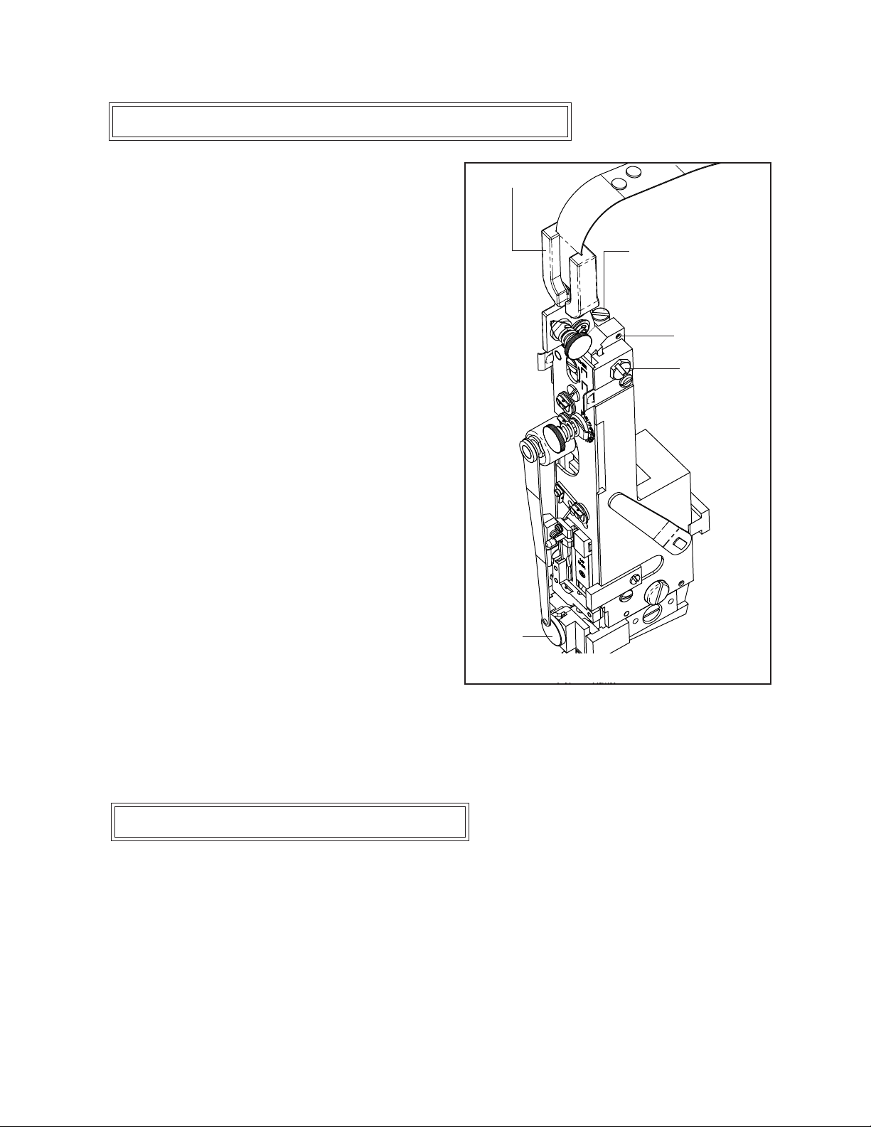
Adjusting the Length of the Left Leg (Figure 6)
Figure 6 - Adjusting the Left Leg
9076
9075
CAAA9074A2
shorter
leg
longer
leg
9038M
090330
The overall length of the stitch is controlled by the amount of wire that is drawn from the spool
after each stroke of the stitcher machine. To change the overall length of the stitch, the stitcher head’s
Face Plate has be to be raised or lowered accordingly.
2601DDPHD Series Head (Figure 7)
Loosen the Face Plate Adjusting Slide Nut (2608) found in the center of the Face Plate (2146MA).
To increase the overall length of the stitch, raise the Face Plate slightly by applying pressure at the
bottom edge of the Face Plate. Use a large screwdriver as a lever under the Wire Cutter Housing area
Adjusting the Wire Draw (Figure 7)

2601DDPHD Series Head (Figure 8)
The final position of the Clincher Points should be
flush, or slightly above flush, with the Clincher Plate
in order to achieve a quality stitch. The best way
to see the
position of
the Clincher
Points is to
manually
cycle the
stitcher
machine to
the position
when the
Driver is at the lowest position of its stroke, the Clincher
Points are at their highest position. Slowly advance the cycle
of the stitcher machine just past this point to reveal the Clincher
Points’ position. Clincher Points that do not pivot high enough
will produce a weak clinch, where Clincher Points that pivot
too high will cause poor stitch quality or mark the stock being
stitched.
If the clinch on the staple is not tight enough, the Clincher
Points (9083A) have to be raised, assuming the Stitcher
machine’s compression setting is correct. If the legs of the
staple are being pushed back through the stock, the Clincher
Points are set too high and have to be lowered. These
adjustments are specific to each stitcher machine and cannot
of the Face Plate. Raising the Face Plate draws more wire from the Wire Spool and increases the
length of each staple leg. To shorten the staple legs or draw less wire from the Wire Spool, lower
the Face Plate slightly by tapping the top edge of the Face Plate. After the adjustments have been
made, tighten the Face Plate Locating Screw. As a rough gauge, the distance the Face Plate is above
the Bonnet (2601M) should be equal to the work thickness. As a rule, this adjustment should only
have to be made once since this style Head automatically adjusts itself when the compression setting
of the Stitcher machine is changed. Some minor modifications may have to be made for individual
jobs though.
11
Figure 7 -Wire Draw on 2601DDPHD
2608
2146MA
Wire Cutter
Housing
Pry up to
raise plate.
Tap down to
lower plate.
Adjusting the Clincher Points
(Figure 8)
Make sure all guards are in place before
operating the stitcher head
WARNING
!
Figure 8 - Adjusting Clincher Points
9083A

12
be fully explained in this manual, since many Machines have Clincher Lever adjustments built in.
Consult the stitcher machine’s operating manual for complete Clincher Point adjustment instruction.
This is especially useful when using non-adjustable Clincher Plates.
Always disconnect the power supply before
making any adjustments or servicing the head.
WARNING
!
Maintenance
Your 26D Stitcher Head has been fully lubricated at the factory, but to insure continuous superior
operation and a longer life of the head, the operator should be sure that the heads are lubricated
regularly and carefully maintained. The operator should periodically inspect all moving parts for
signs of wear and when required, replace the worn parts. Parts such as the Wire Cutters, the Grip,
the Tension Pawl and the Driver are subject to wear and have been so designed to be reversible to
provide duplicate cutting and gripping surfaces. If after continuous usage, the original cutting or
gripping surfaces of any of these parts show signs of wear, their position in the head can be reversed,
thereby providing a new surface and lengthening the life of the part. For a complete list of wear and
replacement parts for your 26D style Stitcher Head, refer to page 32 in the back of this manual.
The following instructions are provided so that the operator will clearly understand how to lubricate
the Stitcher Heads and how to identify and remove any of the parts which may need to be replaced.
Lubrication (Figure 9)
Use any standard S.A.E. #10 oil for lubricating the heads. Heads that are in constant operation
should be lubricated daily. Heads that are operated periodically should be lubricated every five pound
wire spool change or every month, which ever comes first. Usually, only a drop of oil is required at
each lubrication point. Care must be taken that those parts of the head that contact the work to be
stitched are free of oil. Lubricate regularly instead of excessively. Excessive oiling will result in work
becoming spotted with oil. Use one drop of oil in the following lubrication points:

13
• the top of the Bonnet (2601M) on either
side of the Wire Guide Spring Bracket
(CAAA9074A2).
•the oil hole in the Swivel Operating Lever
Hub (2154).
• the oil holes in the Face Plate (2146MA).
• on the Bender Bar Latch (9014EA) and on
the Grip (9015D).
•the opening in the Swivel Holder (2147).
•where the Clincher Points pivot.
•the hole in the Wire Cutter (9048) Holder.
• on the Wire Straightener Rollers (9065B)
and Tension Pawl (9098).
Figure 9 - Lubrication and Cleaning
2154
9065B
2147
9038M
9098
2146MA
CAAA9074A2
9014EA
9015D
9048
2156
2155A
In addition to proper lubrication, routine cleaning is important for the maintenance of your 26D
Head. The entire Head should be torn down and rebuilt every three months and the following areas
should be cleaned once a month:
• Swivel Assembly (9038M): remove and wash in an oil-dissolving solvent, dry
and relubricate.
• Swivel Holder (2147): clean inside the Swivel hole.
• Swivel Operating Lever Hub and Stud: remove the Swivel Operating Spring (2155A), Lever
(2151A) and/or Lever Hub (2154). Clean the Swivel Operating Spring Stud (2156) and the hole
in the Hub, relubricate and replace.
Note: Use care when replacing the Swivel Operating Lever and/or Lever Hub to avoid serious
damage being done to the head.
• Anywhere that dust, oil or pieces of wire and paper have built up - for example: the Grip,
Clincher Points and around the Wire Straightener Rollers.
Cleaning ( Figure 9)

14
In time, you will need to replace some parts in your 26D style Stitcher Head. When this happens,
first locate the needed part in one of the following diagrams. Then locate the DeLuxe/Bostitch
part number and contact your Graphic Arts Representative to order the part by the part number,
description and quantity.
Ordering Spare Parts
The following are some of the more common wear parts which will need to be removed and replaced
in your 26D style Stitcher Head. Some common replacement parts do not require the Stitcher Head
to be removed from the stitcher machine. These parts will be addressed first, then a more specific
explanation for disassembling and
replacing wear parts for the 26D
Stitcher Head will follow.
Removing and Replacing the
Wire Cutters
Figure 11
The Wire Cutters (9048) have
four cutting surfaces, each of
which may be used by reversing
the ends and positioning in the
Face Plate (2132BA or 2146MA).
Worn Cutters can cause poor stitch
quality. To change or reverse
the Wire Cutters, remove them
from the Face Plate. Loosen the
Screws (UA2305.2) securing the
Face Plate Clips (9056) and the
Screw (0084) securing the Solid
Face Plate Clip (9171). Once
the clips are loosened, the Face
Plate can be tilted away from
the Bonnet (2601M) to remove
the Wire Cutters. This may be a
good time to check for wear on
the Wire Cutter Operating Slide
Friction Plug (9050) and Friction
Plug Spring (9051) and replace if
necessary. Slide the existing or
Replacing Spare Parts (Figure 10)
Figure 10 - Replacing Spare Parts
CA9914
CA9024B
9050
9049
CA9012M
2146MA
UA2305.2 (3)
9051
9056 (3)
CA9015D
9171
0084
2601M
9098
9048 (2)
9022
CA9014EA
9029
CA9026A
CA9112
CA9113B
CA9115

15
After replacing or installing new parts, rotate the
Drive Pulley manually to check for free movement.
CAUTION!
!
new Wire Cutters into the cutter holder in the Face
Plate, with the tongue of the upper Cutter facing the
Face Plate and the tongue of the lower cutter facing
the Wire Cutter Operating Slide. Before tightening
the Face Plate Clip Screws and the Solid Face Plate
Clip Screw, make sure that each Cutter has slipped
into position in the Face Plate and in the Wire Cutter
Operating Slide. (9049) Press the Face Plate under
the Face Plate Clips and tighten the Face Plate
Clip Screws. Always cycle the stitcher machine
manually before switching the power on to ensure
free mechanical movement. This will prevent serious
damage to both machine and stitcher head.
Removing and Replacing the Tension Pawl
(Figure 12)
The Tension Pawl (9098) is double-ended so that
when one end is worn, it can be reversed, increasing
the life of the part by providing a new gripping surface.
A worn Tension Pawl may cause inconsistent wire
draw. To remove the Tension Pawl, disengage the Tension Pawl Spring (9134) from the Tension Pawl
and remove the Wire Straightener Roll Clip (9124).
Flip the Tension Pawl over so that a new surface is
in contact with Wire Straightener Roller (9103) and
replace the E-clip. Make sure that the Tension Pawl is
under the flange in the Wire Straightener Roll before
re-engaging the Tension Pawl Spring. If both ends of
the Pawl are worn, replace the part.
Removing and Replacing the Grip (Figure 13)
The Grip (9015D) can be used in two positions so
that when the gripping teeth show signs of wear, it
may be reversed to extend the life of the part. A worn
Grip may cause inconsistent wire draw. Remove the
Grip Spring Housing (9914) to gain access to the Grip
by unfastening the Retaining Clip Screw (9024) and
then remove the Silicone Cap (2182). Remove the
Grip and reverse its position within the Grip Holder.
If both edges are worn, replace the part. While at this
point, check the Grip Spring (9915) in the Grip Spring
Housing. If worn or broken, replace.
Figure 11 - Replacing the Wire Cutters
9048 (2)
9049
9056 (3)
UA2305.2 (3)
9171
Figure 12 - Removing the Tension Pawl
9098
9134
9124
9103

16
Removing and Replacing the Driver (Figure 14)
A worn driver end may result in poorly formed
crowns. To replace the 9012M driver, follow the
section "Disassembling the Stitcher Head" until the
Bender Bar Assy. (9013CA-25) has been removed
(See Figure 15 for reference.). Then loosen and
remove the Friction Bushing (9115) which houses
the Spring (9113B) and Plug (9112). Once these are
removed, the driver can freely slide out from the
assembly. Insert the new driver and reassemble in the
reverse order. (See Figure 15 for reference.)
Disassembling the Stitcher Head (Figure 15)
Remove the 26D style Stitcher Head from the
stitcher machine. On 2601DDPHD series heads,
loosen the Bonnet Clamp Eccentric Handle (9003A)
and remove the Stitcher Head from the Bonnet
Clamp Block (9002).
Release the Swivel (9038M) from the Swivel Holder (2147) by lifting the Swivel Operating Spring
(2155A) off of the Swivel. Continue to rotate the Spring upward until it can be released from the
Swivel Operating Lever Stud (2152) – at approximately the 11 o’clock position. Loosen, but do not
remove, the Screws securing the Face Plate Retaining Clips. With the Face Plate Clips hanging loosely
from the Bonnet, remove the Face Plate paying special attention to the loose Wire Cutters (9048).
Remove the Wire Cutter Operating Slide, the Wire Cutter Operating Slide Friction Plug, the Wire
Cutter Operating Slide Friction Spring and place these
pieces along side of the Bonnet. Remove the Swivel
Operating Lever Hub (2154) from the Stud by first
removing the retaining screw (9058) securing the Stud
to the Bonnet, thus securing the Hub to the Bonnet
as well. Remove this Screw in order to remove the
Stud and Swivel Operating Lever (2151A). Remove
any accessories at this time in addition to the Swivel
Holder.
Remove the Grip Release Slide Lever (9025B) and
Grip Release Slide (9022) and set them aside. Loosen
and remove the Wire Guide Spring Bracket Screw
(9075), which will release the Wire Guide Spring
Bracket (CAAA9074A2) from the top of the Bonnet.
Loosen the Face Plate Locating Screw (2608) and
slide the Face Plate Adjustment Slide Block (2611),
the Face Plate Lock Clamp (2606) and Lock Block
(2607) out the top of the Bonnet. The Driving Slide
Figure 13 - Replacing the Grip
Figure 14 - Replacing the Driver
9015D
2182
9914
9012M
9013CA-25
9024
LW2
9112
9115
9113B

17
Always power down the stitcher machine
before any maintenance or adjustments
are made to the stitcher head.
!
CAUTION
!
Assembly Link (2627A) will be free to slide out of the top of the Bonnet now as well as the Bender
Bar Assembly (9013CA-25). Loosen and remove the Supporter Spring Lever Bushing (9037) as well
as the Supporter Spring (9032). The Supporter Spring Lever Assembly (9036A) will now be swinging
freely within the Bonnet. Loosen and remove the Supporter Spring Lever Screw (9034) to remove
Figure 15 - Disassembling the Head
2146MA
2154
9056 (3)
2155A
9038M
UA2305.2 (3)
0084
9048 (2)
9022
9075
CAAA9074A2
2608
2627A
9013CA-25
2152
9058
2151A
9025B
9036A
9032
9037
2606
2607
9034
LW8
2147
9012M

18
the Lever Assembly from the Bonnet.
Any of these assemblies can now be taken apart for cleaning or repair. The Bonnet itself can also
be cleaned or checked for damage. Most common wear parts can be exchanged while the Head is still
assembled though. Reassembling the Head is as simple as reversing the method used to disassemble
the Head. Always turn the machine over manually anytime repairs or adjustments are made for the
safety of both the operator and the Stitcher Head.
Re-assembling the Stitcher Head (Figure 19)
1. Insert the Supporter Spring Lever Screw (9034) through the Supporter Spring Lever Assembly
(9036A) and into the Bonnet. Grease one end of the Supporter Spring and insert it into the Supporter
Spring Lever Bushing (9037). Insert both the Spring and Bushing into the back of the Bonnet but do
not tighten the Bushing completely at this point.
2. Start the Bender Bar Assembly (9013CA-25) into the top of the Bonnet. Hook the Bender Bar
Assembly in the notch of the Driving Slide Assembly Lug (2627A) and finish guiding both assemblies
between the rails of the Bonnet.
3. Slide the Face Plate Lock Clamp (2606) and Block (2607) or the Face Plate Adjustment Slide
Block (2611) into the top of the Bonnet but do not tighten the Face Plate Locating Screw at this point.
Next, slide the Wire Guide Spring Bracket (CAAA9074A2) into the top of the Bonnet and secure it
with the Wire Guide Spring Bracket Screw (9075).
4. Secure the Grip Release Slide Lever (9025B) on the Pivot Pin on the Wire Guide Spring Bracket.
Oil the right rail of the Bonnet slightly, engage the Lever in the notch of the Grip Release Slide (9022)
and rest the Slide on the rail of the Bonnet.
5. Grease one end of the Wire Cutter Operating Slide Friction Spring (9051) and the Wire Cutter
Operating Slide Friction Plug (9050) and insert both into the Bonnet. Rest the Wire Cutter Operating
Slide (9049), along the left Bonnet rail, on the Friction Plug. Secure the Swivel Operating Lever
(2151A), the Swivel Operating Lever Hub (2154) and the Swivel Operating Lever Stud (2152) to the
Bonnet. Verify the orientation is correct.
6. Secure the Face Plate (2146MA), with the Wire Cutters (9048), to the Bonnet by tightening the
Screws (UA2305.2 and 0084) securing the Face Plate Clips (9056 and 9171). Make sure the internal
assemblies move freely before mounting the Head on a Machine.
After replacing or installing new parts, rotate the
Drive Pulley manually to check for free movement.
CAUTION!
!

19
The quality and quantity of work that can be produced with the 26D Stitcher Head is dependent upon
the operator making all adjustments as accurately as possible and carefully maintaining the head. The
cause of staple imperfections usually can be traced to inaccurate settings or normal wear of moving
parts. In the event of trouble of this nature occurring, the operator can, by referring to the following
troubleshooting chart, quickly locate and remedy the cause or causes of the trouble. The following is
a brief list of problems and solutions which should cover the majority of situations encountered when
stitching with the 26D Stitching Head.
problem: Left Leg Short
solution: Lengthen the left leg. (See Fig. 6) Check the Grip for wear and
clean, rotate or replace it if needed. (See Fig. 13 instructions)
problem: Right Leg Short
solution: Shorten the left leg to match the right leg, then adjust both legs to
desired length by adjusting the Face Plate. (See Figs. 6 & 7 instructions)
problem: Corner Buckled
solution: Check the Driver (9012M) for a chipped corner and
rotate or replace it if needed. (See Fig. 14 instructions) Check the tensile
strength of the wire or use thicker wire.
problem: Leg(s) Buckled
solution: If the ends of an unformed piece of wire are not smooth,
the Wire Cutters (9048) are worn. Check for wear and rotate or replace
if needed. (See Fig. 11 instructions) Make sure the correct wire size is being
used and that the wire is straight.
problem: Crown Bent or Buckled
solution: Check Supporter Spring (9032) tension, adjust the
Supporter Spring Lever Bushing or replace the Spring if needed. Check
for correct wire size being used. Check for correct work thickness setting.
Make sure there is not too much chamfer on the Swivel or that it is worn.
Troubleshooting (Figure 16)
Figure 16 - Troubleshooting

20
problem: Partially Formed Stitches
solution: Replace the worn Driver Bar Latch (9014EA) or Driver
Bar (9012M). The Grip Spring (9915) in the Grip Spring Housing (9914)
could be worn or broken, replace it. (See Fig. 13 instructions)
problem: Stitch in Pieces or Right or Left Leg Sheared Off
solution: Clean and lubricate Swivel (9038M). (See Fig. 9 instructions)
Loosen the Swivel Holder Screw and correct the alignment between the
Swivel Holder and the Bender Bar. If problem persists, file the forming
corner of the Swivel slightly with a honing stone.
problem: Left Leg Missing
solution: Clean the Grip (9015D). Reverse or replace the part if
needed. (See Fig. 13 instructions) Make sure the Wire Straightener Rollers
are not set too tight. Make sure the Tension Pawl is not worn and is pivoting
correctly. (See page 12 instructions)
problem: Corner of stitch broken or nearly cut through
solution: File the forming corner of the Swivel slightly with a honing
stone if too sharp. Lower Clincher Points (9083A) if too high. (See Fig. 8
instructions) Loosen the Swivel Holder Screw and correct the alignment
between the Swivel Holder and the Bender Bar.
problem: Corners of the Crown are Rounded
solution: Replace the worn Swivel (9038M).
problem: Loose Clinch
solution: Check thickness setting for work or raise Clincher Points
(9083A). (See Fig. 8 instructions)
problem: Legs are Spread or Contracted
solution: Re-adjust the Wire Straightener Eccentrics to improve
straightness. (See Fig. 6 instructions) Check the Wire Cutters for wear and
rotate or replace. (See Fig. 11 instructions) Check the Bender Bar (9013CA-
25) for wear in the grooves and replace if necessary.
problem: No wire being drawn
solution: Lower the Face Plate. (See Fig. 7 instructions)
Figure 16 - Troubleshooting
This manual suits for next models
1
Table of contents
Other DeLuxe Stitcher Sewing Machine Accessories manuals