EGAmaster Aqua Master 79908 User manual
HAMMER DRILLS
OPERATING INSTRUCTIONS
GUARANTEE...................................9
COD. 79908
2
OPERATION AND MAINTENANCE MANUAL
Operating pressure 90 PSI max. 6 bar
Air connection R 1/2” female R 1/2“
Motor output 1.61 HP 1,5 kW
Air consumption 21 cfm 1,5 m3/min
I/D of hose 0.51 inches 13 mm
Free speed 250 rpm 250 1/min
Speed under load 150 rpm 150 1/min
Percussion drilling under load 0-2500 blows/min 0-2500 Schläge/ min
Drilling range in concrete 0.4724 – 1.1968 inches dia. Ø12- 50 mm
Drilling capacity in concrete of medium
hardness
0.7874 dia. =
7.078 cu. in =
14.56 inches/ min
Ø20 mm= 116 cm3/min
= 370 mm/min
Optimum drilling performance in concrete 0.4724 -1.5748 inches dia. Ø20- 40 mm
Drilling in wood (with quick-release chuck) 0.3937 – 1.2598 inches dia. Ø10-32 mm
Motor oil capacity 3.05 cu.in. 50 cm3
Weight (without hoses) 29.32 lbs 13.3 kg
Dimensions (L x H x W) 25.19x4.92x10.83 inches 640 x 125 x 275 mm
Tool holder SDS Max
Sound level 90.4 dB (A)
Vibration measurement 9.2 m/s2
Safety clutch for protection against overloading and accidents
Sealed Gears with permanent lubrication (maintenance free)
Adjustable side handle with depth gauge and water ushing.
Supplied kit: 1 carrying case, 1 dust guard, 1 oil ampul (50 cc)

3
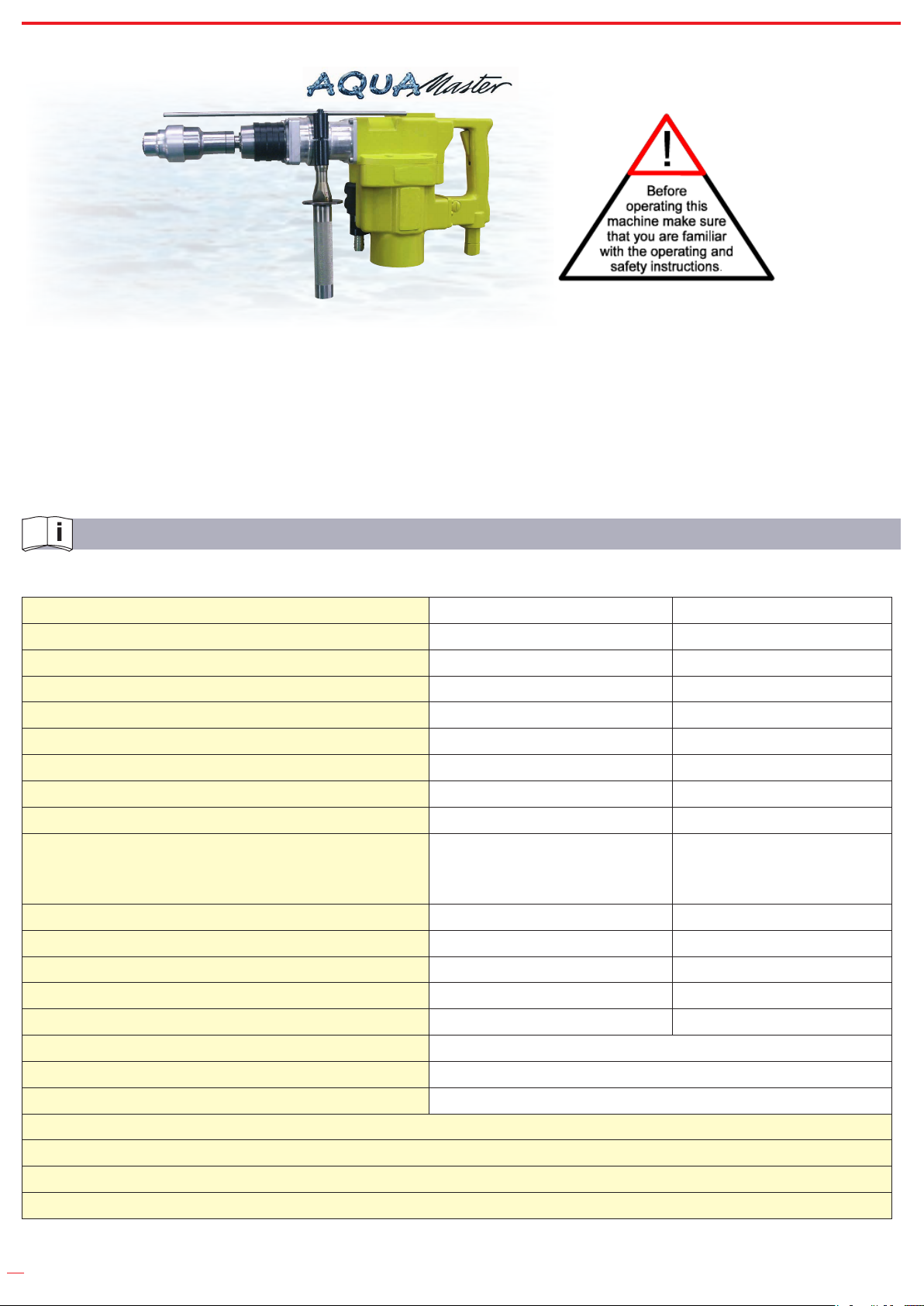
SAFETY INSTRUCTIONS
Any power tool can be dangerous.
Please follow these simple procedures. They are for your protection.
Wear goggles ( chips – risk of injury)
Wear gloves (cutting damages by sharp edged work pieces)
Wear safety shoes
Wear protective clothing.
Remove rings, watches, ties etc. that could be torn by the machine.
Dress properly. Do not wear loose clothing or jewellery, it can be caught in moving parts.
Follow the general current and appropriate Accident Prevention and Safety Procedures.
Never work under the inuence of alcohol, drugs or stronger medication.
Always make sure that you have a safe foothold.
Maintain a proper footing and balance at all time. Never work with the machine while standing on a ladder or
leaning against a scaffold.
Secure the working place well. Use clamps or a vice to x the work piece. This is safer than using hands and clears
both hands for operating the machine.
Hold the machine tight during operation.
Keep your working area clean and uncluttered.
Keep children away and avoid other persons to come into contact with the machine.
Switch off the machine if it stops - for any reason - to avoid the unexpected starting in uncontrolled condition.
Do not operate the tool if it is damaged, improperly adjusted or not completely and correctly assembled.
Check hydraulic hose for damage.
Avoid sparks in hazardous environment - created by the tool. Always ush material and saw blade for cooling with
sufcient water during working.
Do not employ machines by excessive force. Their performance is better and safer, if they work at the prescribed
speed.
Check damaged parts.

4
Before using the machine, damaged parts or protective devices should be carefully checked to make sure they work
soundly and full the designated function. Check alignment, connections and attachment of moving parts. Also check
if parts are broken. Parts or protective devices that are damaged should, if nothing else is mentioned in these operating
instructions, only be exchanged or repaired by qualied personnel. The same applies to defective switches and valve
triggers. If the machine cannot be switched on or off with the valve trigger, it should not be used.
The use of other accessories, or other additional items than recommended in these operating instructions, may
include the risk of bodily injury.
Only operate the tool after a thorough training or under supervision of a trainer.
Never exceed the maximum operation pressure.
Follow the valid national provisions in the country of application.
ATTENTION! Never use the hydraulic hose as a lifting handle!
USE
INTENDED USE
The machine is designed for drilling into concrete and masonry. The machine is intended to be used by professional
operators. Only authorized and trained personnel may use, maintain and repair the machine. The personnel has to be
especially instructed on the potential dangers. The working environment can be: construction site, factory, renovation,
rebuilding and building. Manipulation or modications to the machine are not allowed. Observe the instructions
regarding the operation, care and maintenance in the operation instruction. Dangers can come from the machines and
the auxiliary materials, if improperly handled or used.
IMPROPER USE
Any use deviating from the intended use as described is considered to be improper use. Working without personal
protection equipment.
Danger Zones
Operational
condition
--------------------
Life phase
Normal function Malfunction Improper use Expected use
Transport
Transport of
the machine in
an inoperable
condition
Drop of the
machine
Transport of the
machine in an
operable condition
unknown
Operation
Machine only works
with actuated valve
Machine runs
without actuated
valve
Switch is blocked in
actuated condition unknown
Machine moves the
tool Tool blocks unknown unknown
Maintenance Operation at a
maintenance unit
Breakdown of the
machine unknown unknown

5
OPERATION INSTRUCTIONS
Before using the machine:
Open oil plug item 4 and pour in oil from oil ampul in the machine box.
Do not exert undue pressure on the machine. This will not increase its performance. Just position the bit and guide it
into the hole.
Placing the machine into the box
Make sure the adjusting sleeve is locked at the setting “rotary hammer drilling”.
Side handle
This can be turned through 360°and clamped in any desired position.
Depth gauge
Press unlock button, adjust the depth gauge and release button.
Lubrication of shank end
Occasionally clean shank ends and spray sparingly with lubricant sprayer. Do not spray into the chuck.
Fig. 1 Fig. 2 Fig. 3 Fig. 4 Fig. 5
Fig. 1: Drilling in explosive surroundings
The drill must be water cooled to avoid sparks.
Fig. 2: Rotary hammer drilling
Pull back the adjusting sleeve and turn it clockwise to lock. Do not use the quick-release chuck at this setting because
drills and tools will be damaged.
Fig.3: Pull back the locking sleeve and insert the drill. Turn the locking sleeve until it snaps back into the outset
position. Press the machine against the work surface before switching on otherwise the tool will not hammer. If the drill
sticks in the hole, withdraw and reinsert it several times when drilling.
Table of contents
Other EGAmaster Drill manuals

EGAmaster
EGAmaster 79605 User manual

EGAmaster
EGAmaster 79632 User manual

EGAmaster
EGAmaster 79915 User manual

EGAmaster
EGAmaster 79907 User manual

EGAmaster
EGAmaster AQUAMASTER 79915 User manual

EGAmaster
EGAmaster MASTEREX 79330 User manual

EGAmaster
EGAmaster 79904 User manual

EGAmaster
EGAmaster MASTEREX 79303 User manual

EGAmaster
EGAmaster AQUAMASTER 79916 User manual

EGAmaster
EGAmaster 79906 User manual


