EGi 06701 User manual
06701 manual de instrucciones
instructions manual
EN 54-24
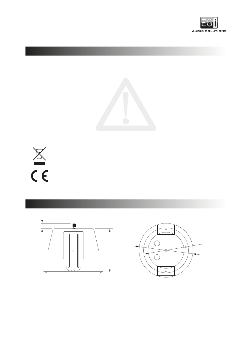
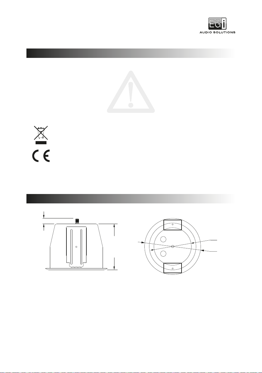
125 mm
- 2 -
22 mm
157 mm
180 mm
06701
ALTAVOZ DE EMPOTRAR DE 5”
ADVERTENCIAS DE SEGURIDAD
DIMENSIONES
• La instalación en techo, en pared o en cualquier otro soporte, de un objeto supone un peligro potencial y solo debe
llevarla a cabo personal instalador especializado con conocimientos técnicos y normativos específicos.
• El personal instalador es responsable de garantizar que los altavoces y proyectores se instalen de forma segura.
• El usuario es responsable de garantizar que el material donde se va a instalar el altavoz o proyector se encuentra
en buen estado y es capaz de aguantar su peso.
• EGi recomienda que todos los altavoces y proyectores se instalen teniendo en cuenta las leyes y normativas aplicables.
• Se recomienda revisar la instalación una vez al año por si se detectará alguna anomalía subsanarla inmediatamente.
• EGi no se responsabiliza de los materiales utilizados en la instalación que no hayan sido suministrados por la
propia compañía.
• Utilice únicamente los accesorios suministrados por EGi.
• EGi declina toda responsabilidad que derive del uso impropio del producto o de un uso distinto de aquel para el
que está destinado (ver el apartado Garantía).
El presente producto no puede ser tratado como residuo doméstico normal, sino que debe entregarse en el
correspondiente punto de recogida de equipos eléctricos y electrónicos.
Este producto es conforme a las Directivas Europeas que le aplican.

- 3 -
8
7
2
1 3 4 5 6 7
9
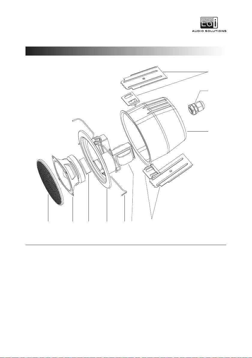
1Rejilla.
2Altavoz.
3Regleta de conexión.
4Aro.
5Muelle.
6Transformador.
7Lengüetas de anclaje.
8Cubierta.
9Prensaestopas.
06701
ALTAVOZ DE EMPOTRAR DE 5”
DIAGRAMA DE EXPLOSIÓN
- 4 -
2
4
1
3
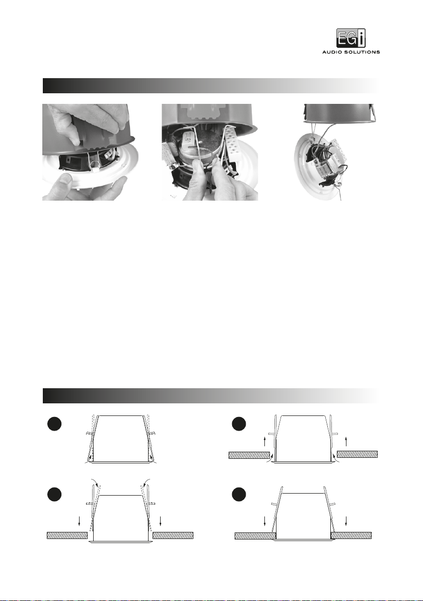
MONTAJE DEL ALTAVOZ
INSTALACIÓN EN TECHO
06701
ALTAVOZ DE EMPOTRAR DE 5”
1En primer lugar, separe el aro blanco de la cubierta roja. Para ello, tire con decisión del aro mientras sujeta firmemente
la cubierta.
2Suelte uno de los muelles que sujeta el aro a la cubierta y deje el otro muelle sin soltar de tal manera que el aro quede
sujeto a la cubierta por el mismo.
3Afloje las tuercas con forma de mariposa que hay dentro de la cubierta y gire las lengüetas de anclaje de tal manera
que los dientes queden hacia abajo.
4Pase el cable del altavoz a través del prensaestopas de la cubierta.
5Inserte el altavoz en el agujero del techo y ajuste las lengüetas de anclaje contra el panel del falso techo mediante las
tuercas de mariposa.
6Una vez la cubierta esté fijada sólidamente al techo, conecte los cables a la regleta de conexión del altavoz, tal como muestra
el esquema eléctrico.
7Finalmente inserte los extremos del muelle en su posición correcta y empuje el aro hacia arriba para cerrar el altavoz.
- 5 -
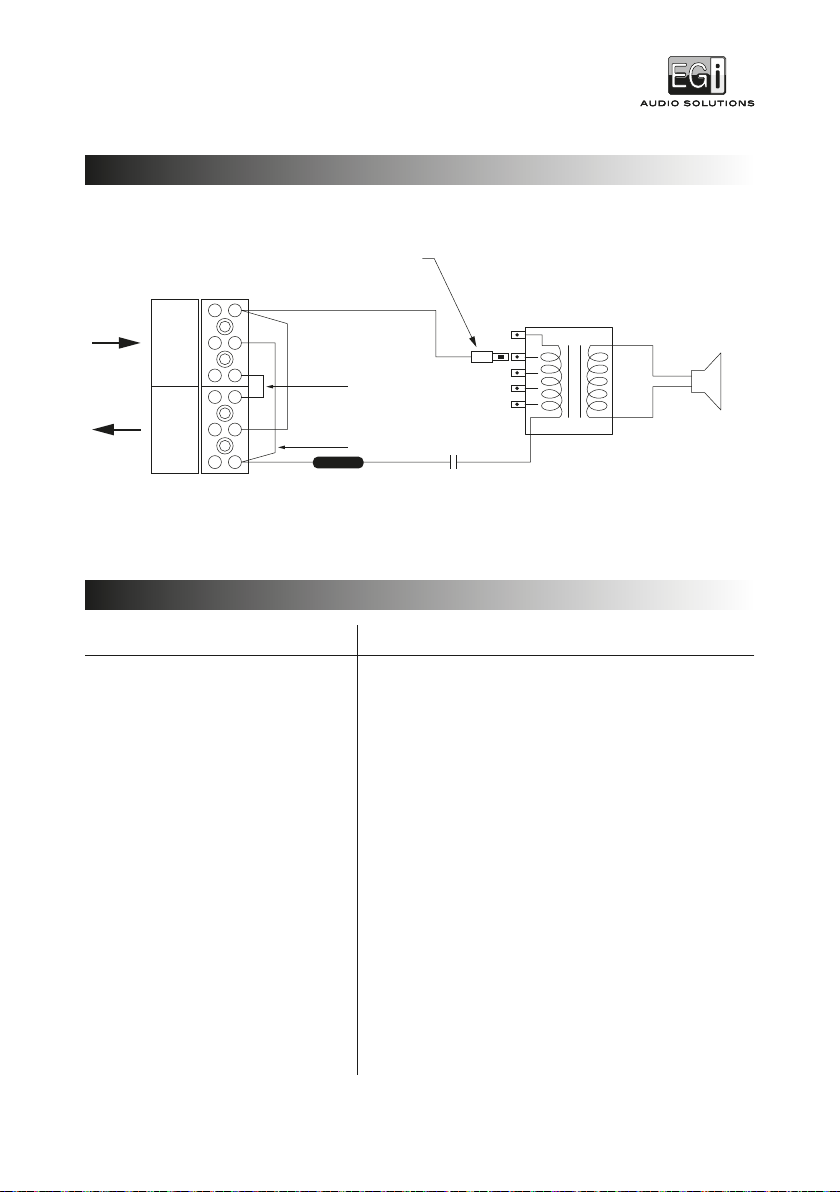
3.3 µF
250 V~
Faston
8 Ω
6 W
3 W
1.5 W
0.75 W
0.38 W
IN
CT CT+ – + –
OUT
+
–
06701
ALTAVOZ DE EMPOTRAR DE 5”
ESQUEMA ELÉCTRICO
Datos técnicos
Potencia RMS @ 100V
Potencia RMS @ 70V
Impedancia
Sensibilidad (@ 1 W/4 m)
Máximo nivel de presión sonora (6 W/4 m)
Potencia de ruido nominal
Acabado
Ángulo de cobertura a 500 KHz
Ángulo de cobertura a 1 KHz
Ángulo de cobertura a 2 KHz
Ángulo de cobertura a 4 KHz
Respuesta en frecuencia
Controlador del altavoz
Diámetro de corte
Peso
Dimensiones
06701
0.38 / 0.75 / 1.5 / 3 / 6 W
0.19 / 0.38 / 0.75 / 1.5 / 3 W
13300 / 6790 / 3340 / 1840 / 1240 Ω
73 dB
86.5 dB
6 W
Bafle y rejilla: acero, blanco / Cubierta: acero, rojo
180º
180º
150º
70º
130-18 KHz
5"
ø157 mm
1.35 Kg
180 x 147 mm
DATOS TÉCNICOS
Verde (CT)
Negro (–)
Negro (–)
Rojo (+)
Fusible térmico
150º 250 V~ 5A
La siguiente figura muestra el modo de conexionado del altavoz:

- 6 -
1 3 4
5
6
2
Las mediciones se han realizado de acuerdo a la norma EN 54-24:2008 dentro de una cámara anecoica con la condición
de campo libre en espacio hemisférico.
Eje de referencia: eje que está en el centro de la superficie de la rejilla y perpendicular a la misma.
Plano de referencia: plano que está en la superficie de la rejilla y perpendicular al eje de referencia.
Plano horizontal: plano que contiene el eje de referencia y es perpendicular al plano de referencia.
Eje de referencia, plano de referencia y plano horizontal.
ENTORNO UTILIZADO
PARA LA TOMA DE MEDIDAS ACÚSTICAS
06701
ALTAVOZ DE EMPOTRAR DE 5”
1Caja del altavoz.
2Ejes de referencia.
3Puntos de referencia.
4Plano de referencia.
5Plano horizontal.
6Plano vertical.
H: ±30º; V: ±20º; Referencia: 3 m.

- 7 -
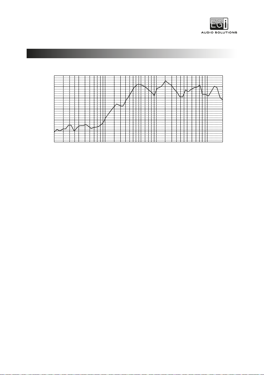
10 20 50 200 500100 1 K 2 K 5 K 10 K 20 K
40
50
60
70
80
90
100
Frequency in Hz
SPL in dB
RESPUESTA EN FRECUENCIA
06701
ALTAVOZ DE EMPOTRAR DE 5”

-8 -
EGi garantiza sus fabricados electrónicos y electroacústicos contra cualquier defecto de fabricación que afecte a su
funcionamiento durante 36 meses a partir de la fecha de su producción (indicada en cada fabricado), comprometiéndose
a reparar o reponer los módulos defectuosos cuyo fallo, siempre a juicio de EGi, se deba a defecto de fabricación, sin
cargos de repuestos.
Esta garantía no incluye mano de obra de sustitución en la instalación de los citados módulos electrónicos y electroacústicos.
En ningún caso la garantía cubre los desperfectos o roturas de piezas embellecedoras (rejillas, embellecedores, carátulas,
marquillos...).
Esta garantía se refiere únicamente al concepto de sustitución en fábrica de los módulos producidos por EGi, excluyéndose
cualquier otra cobertura o responsabilidad sobre el resto de materiales o el conjunto de la instalación puesta a disposición
del usuario, pero que EGi no suministra ni ejecuta.
Por lo tanto no quedan cubiertas por esta garantía:
a) La instalación e interconexionado entre sus módulos.
b) Las consecuencias de abuso o mal uso del producto, incluyendo pero no limitado a:
b.1.) No usar el producto para fines normales, o no seguir las instrucciones de EGi, para el correcto uso y
mantenimiento del mismo.
b.2.) La instalación o utilización de los productos de forma no concordante con las normas técnicas o de seguridad
vigentes.
c) Las averías producidas por la incorrecta instalación de los módulos o por su instalación con cable de características distintas al
indicado por EGi.
d) Las averías generadas por intervención de persona no autorizada por EGi.
e) Las consecuencias de mezcla con equipos de otro origen, así como adaptaciones, modificaciones, ajustes y/o tentativas
de ajustes, independientemente de que ello haya sido efectuado de forma técnicamente correcta, siempre que no exista
expresa autorización por EGi.
f) Las consecuencias de accidentes, catástrofes naturales o cualquier causa ajena al control de EGi, incluyendo pero no
limitado al rayo, agua y disturbios públicos. En todos estos casos excluidos de la garantía, y siempre que los módulos
no sean juzgados como defectuosos por parte de EGi, su remitente deberá hacerse cargo del importe total de la
reparación, y caso de producirse visita de nuestros técnicos, su solicitante correrá con los gastos originados.
Esta garantía no afecta a los derechos derivados del Real Decreto Legislativo 1/2007 de 16 de Noviembre, referido al LIBRO II
sobre contratos y garantías. El comprador puede ejercitar dicha garantía dirigiéndose al S.A.T. de EGi a través de correo ordinario
o electrónico, fax, web o teléfono.
GARANTÍA
06701
ALTAVOZ DE EMPOTRAR DE 5”
125 mm
22 mm
157 mm
180 mm
- 9 -
06701
5" CEILING LOUDSPEAKER
• Installing an object in ceiling, wall or any other surface is a potential danger and should only be carried out by
specialized installer with specific technical and regulatory knowledge.
• The installer is responsible for ensuring that speakers and projectors are installed in a safety way.
• The user is responsible for ensuring that the material where the speaker or projector is to be installed is in good
condition and can support its weight.
• EGi recommends that all speakers and projectors be installed taking into account laws and standards that applied.
• It is recommended to check the installation once a year in case any anomaly is detected to correct it immediately.
• EGi is not responsible for the materials used in the installation that have not been supplied by the company itself.
The product indicates that this product should not be treated as household waste. Instead it shall be
handed over to the appicable collection point for the recycling of electrical and electronic equipment.
This product is in accordance with the European Directives that apply to it.
DIMENSIONS
SAFETY INSTRUCTIONS
- 10 -
8
7
2
1 3 4 5 6 7
9
EXPLODED DIAGRAM
06701
5" CEILING LOUDSPEAKER
1Grille.
2Speaker.
3Terminal block.
4Ring.
5Metal spring.
6Transformer.
7Tabs.
8Cover.
9Cable gland.

- 11 -
2
4
1
3
SPEAKER ASSEMBLY
06701
5" CEILING LOUDSPEAKER
CEILING INSTALLATION
1Firstly, separate the white ring from the red cover. To do this, pull the ring while holding the cover firmly.
2Release one of the metal spring that holds the ring to the cover. Keep the other metal spring fastened in such a way
that the ring is attached to the cover by it.
3Loosen the wing nuts of the inside of the cover and rotate the tabs in order to maintain the teeth facing down.
4Pass the speaker cable through the cable gland.
5Insert the speaker into the hole in the ceiling and adjust the tabs against the false ceiling panel using the wing nuts.
6Once the cover is firmly fixed to the ceiling, connect the cables to the speaker terminal block, as shown in electric
scheme.
7Finally insert the metal spring in its correct position and push the ring up to close the speaker.

- 12 -
3.3 µF
250 V~
Faston
8 Ω
6 W
3 W
1.5 W
0.75 W
0.38 W
IN
CT CT+ – + –
OUT
+
–
06701
5" CEILING LOUDSPEAKER
ELECTRIC SCHEME
Technical data
Power RMS @ 100V
Power RMS @ 70V
Impedance
Sensitivity (@ 1 W/4 m)
Maximum sound pressure level (6 W/4 m)
Rated noise power
Finish
Coverage angle at 500 KHz
Coverage angle at 1 KHz
Coverage angle at 2 KHz
Coverage angle at 4 KHz
Frequency response
Speaker driver
Cutout size
Weight
Dimensions
06701
0.38 / 0.75 / 1.5 / 3 / 6 W
0.19 / 0.38 / 0.75 / 1.5 / 3 W
13300 / 6790 / 3340 / 1840 / 1240 Ω
73 dB
86.5 dB
6 W
Baffle and grille: steel, white / Cover: steel, red
180º
180º
150º
70º
130-18 KHz
5"
ø157 mm
1.35 Kg
180 x 147 mm
TECHNICAL DATA
Green (CT)
Black (–)
Black (–)
Red (+)
Thermal fuse
150º 250 V~ 5A
The following figure shows the connection mode of the speaker:

- 13 -
1 3 4
5
6
2
The measurements have been made according to EN 54-24:2008 within an anechoic chamber with the condition of free
field in hemispheric space.
Reference axis: axis that is in the center of the surface of the grid and perpendicular to it.
Reference plane: plane that is on the surface of the grid and perpendicular to the axis of reference.
Horizontal plane: plane that contains the reference axis and is perpendicular to the plane of reference.
Reference axis, reference plane and horizontal plane.
ACOUSTICAL MEASUREMENT ENVIRONMENT USED FOR THE SPECIFICATION
ACOUSTICAL MEASUREMENT ENVIRONMENT USED
FOR THE SPECIFICATION
06701
5" CEILING LOUDSPEAKER
1Loudspeaker enclosure.
2Reference axis.
3Reference point.
4Reference plane.
5Horizontal plane.
6Vertical plane.
H: ±30º; V: ±20º; Reference: 3 m.
- 14 -
06701
5" CEILING LOUDSPEAKER
FREQUENCY RESPONSE
10 20 50 200 500100 1 K 2 K 5 K 10 K 20 K
40
50
60
70
80
90
100
Frequency in Hz
SPL in dB

- 15 -
EGi warrants its products against any manufacturing defect that could affect itsworking for 36 months from the date of production
(indicated on each product), involving a repair or replacement of defective modules whose fault, if in the opinionof EGi, is due to
manufacturing defect.
This warranty does not include the labor cost of replacements’ installation.
This warranty doesn’t cover in any case damaged or broken pieces such as grilles,trims, accessories.
This warranty applies only to the concept of factory replacement modules producedby EGi, excluding other materials that
can be part of the installation but notprovided by EGi.
Therefore this warranty doesn’t cover:
a) The installation and connection of the modules.
b) The consequences of abuse or misuse of the product, including but not limited to:
b.1.) The use of the product for unusual purposes, or failure in following EGi’s instructions, for a proper use and
maintenance.
b.2.) The installation or use of products not accordingly to the technical or safetyregulations.
c) Damages caused by a wrong installation of the modules or wiring with other thancable features indicated by EGi.
d) Damages caused by the intervention of a person not authorized by EGi.
e) The consequences of mixing with equipment from other manufacturer such asadaptations, modifications, adjustments and/or
adjustment attempts, even if ithas been performed in a technically correct way, if there is no express authorizationfrom EGi.
f) The consequences of accidents, natural disasters or any other cause beyond thecontrol of EGi, including but not limited
to lightning, flooding and public disturbances.
In all these cases excluded from the warranty and as far as the modules are notconsidered as faulty by EGi, the sender shall bear
the entire cost of the repair, andin case of the necessary visit of our technicians, the applicant shall also bear theincurred costs.
Warranty claims.
How to proceed:
1. Send the defective goods to EGi S.A. to the attention of Repairs Department.Please include the necessary documents for
the accurate identificationof the products and problem: cause of failure, date of mounting… All information that you could
provide is highly appreciated, as allows usto give you a quick response. Please also inform our Sales Department.
The transport costs of the warranties delivery will be at the client’s expense.
2. Our Sales Department will prepare a Guarantee report stating whether the itemis accepted or rejected. If it is rejected,
the report will include the causes of therejection.
3. Accepted items: EGi will repair the goods and send them back. EGi will not be liablefor any third party or consequent claim
or labour charge.
4. Rejected items: Items will be returned in the next delivery, unless the customerasks for its returning urgently. In this
case, the transport will be at the client’scost.
WARRANTY
06701
5" CEILING LOUDSPEAKER
Avda. Almozara, 79 • 50003 Zaragoza - SPAIN
T. +34 976 40 53 53 - +34 976 40 53 56
F. +34 976 40 53 54
e-mail: [email protected]
www.egiaudio.com
009149 · 06/2019
1438
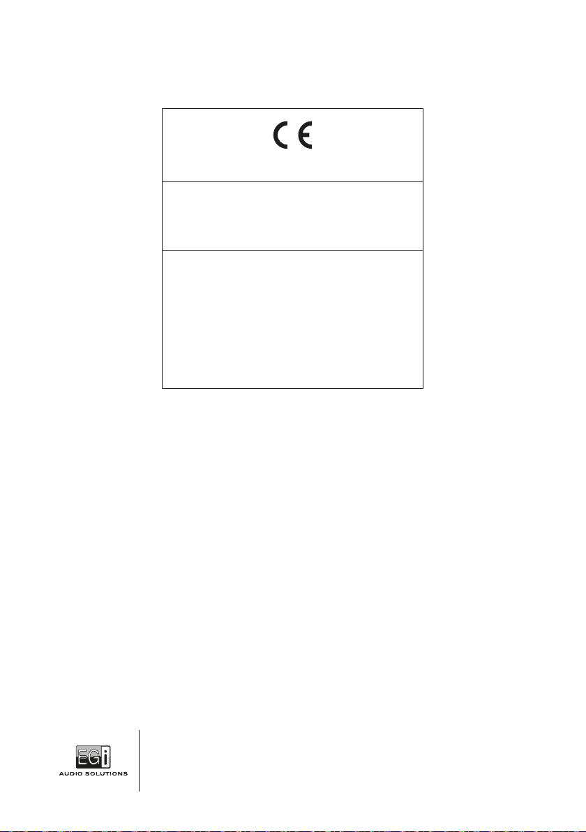
EGi. S.A. (Electroacústica General Ibérica, S. A.)
Avda. Almozara, 79 • 50003 - Saragossa - SPAIN
1438-CPR-0629
EN 54-24:2008
Fire detection and fire alarm systems
Part 24: Components of voice alarm systems - Loudspeakers
Ceiling loudspeaker 06701
Type A
19
Table of contents
Languages:
Other EGi Speakers manuals


