EIJKELKAMP 04.01 User manual

1
1
04.01/04.02 GOUGE AUGERS
M1.04.E© July 2008
OPERATING INSTRUCTIONS
www.eijkelkamp.com
P.O. Box 4, 6987 ZG Giesbeek, NL
T+31 313 880200
F+31 313 880299
Contents
On these operating instructions ..........................................................................................................................2
Introduction ......................................................................................................................................................2
1. Description ...................................................................................................................................................2
1.1 General information ............................................................................................................................2
1.2 Single gouge auger set for more or less soft soils.................................................................................3
1.3 Single gouge auger set for hard soils ..................................................................................................3
1.4 Single gouge auger set for very hard soils ............................................................................................3
1.5 Bi-partite gouge auger for more or less soft soils..................................................................................4
1.6 Bi-partite gouge auger set for hard soils...............................................................................................5
2. Technicalspecications ..................................................................................................................................6
3. Safety Instructions..........................................................................................................................................6
4. Preparing for use ...........................................................................................................................................7
5. The use of gouge augers................................................................................................................................8
5.1 Single gouge augers for more or less soft soils.....................................................................................8
5.2 Single gouge augers for hard soils ......................................................................................................8
5.3 Single gouge auger set for very hard soils ............................................................................................9
5.4 Bi-partite gouge auger sets..................................................................................................................9
6. Applications.................................................................................................................................................11
7. Troubleshooting...........................................................................................................................................12
8. Maintenance................................................................................................................................................13
Appendix: Rust on augers and gouges .............................................................................................................14
2
On these operating instructions
When the symbol shown on the left is placed before a piece of text, this means that an impor-
tant instruction follows.
When the symbol shown on the left is placed before a piece of text, this means that an impor-
tant warning follows pointing out a risk of injury to the user or damage to the device.
The user is always responsible for it own personal protection.
Text in italics means that the actual text is shown on the display screen.
Introduction
In soil research to a depth of 5 to 10 meters hand auger equipment may be used. Gouge augers are often used in
cohesivesoilsandmayeasilyproduceanoverviewofproleswithhardlydisturbedsamples.Single,non-extend-
able gouge augers, and bi-partite, extendable gouge augers are available. These instructions deal with various sets
of types of gouge augers.
Upon erosion of rock soils are formed and transported by natural processes to be deposited elsewhere. Soils con-
sistofminerals,organicmaterialandcavitieslledwithairand/orwater.Themineralsmayvaryinsizeofclayand
loam (<63 mm) and sand (63 mm – 2 mm), to gravel (2 - 63 mm and stones (>63 mm).
Soilinitsnaturalpositionmayconsistofvarioussoiltypes(stratiedorheterogeneoussoil).Differencesintexture
orsoil-formingprocessesleadtostratication.Soilstypewillvaryfromclay,loam,sandtostonysoil,dependingon
its loam and sand content. Peaty soil mostly consists of organic material. Cohesive soils, for instance, are wet clay,
loam and peaty soil. Sand and stony soils are moderately cohesive.
Gougeaugersetsareoftenusedinproleresearchforsurveyingpurposes,soilassessmentandrootagesurveys.
Standard gouge augers are suitable for use in soft soils such as peat, clay and sandy or disturbed soils. Heavy-duty
gouge augers have been developed for hard soils such as loam and stony soils. They are driven into the soils using
a hammer. The single type sets are suitable for topsoil research. The bi-partite auger sets are used in soil research
to a depth of 5 m, depending on soil structure and soil composition.
1. Description
1.1 General information
All gouge augers have similar characteristics:
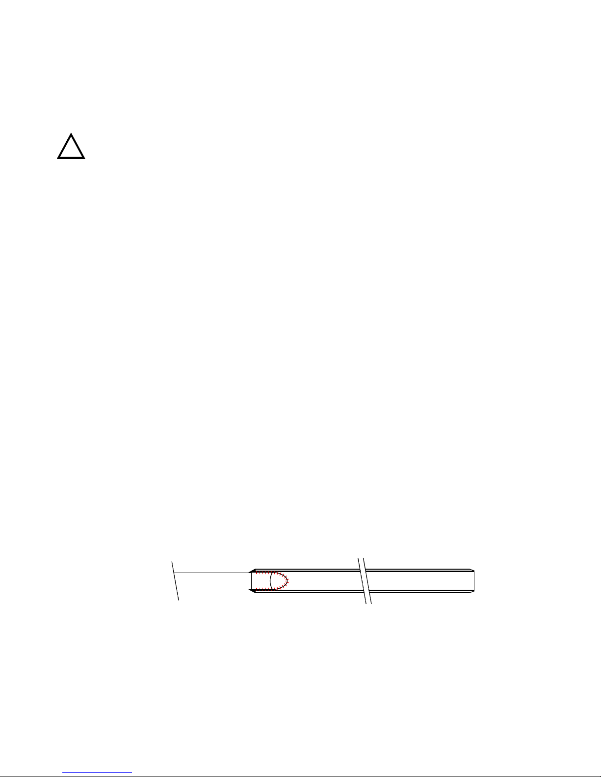
The auger body is half-cylindrical with parallel running cutting edges. The standard effective auger body measu-
res 50 or 100 cm. The diameter may vary, but 30 mm is standard.
The gouge augers are made from high-quality steel, which under normal conditions will not permit torsion of
the auger body.
The gouge auger body has a 10-cm calibration.
Single gouge augers are not extendable; auger body and grip are integrated, rendering stability and easy use in
topsoil research.
The bi-partite gouge auger is extendable; its parts (upper part, and bottom part with auger body, and extensi-
ons can be coupled using a bayonet or a conical thread connection.
!
Text
Gouge auger body
2
3
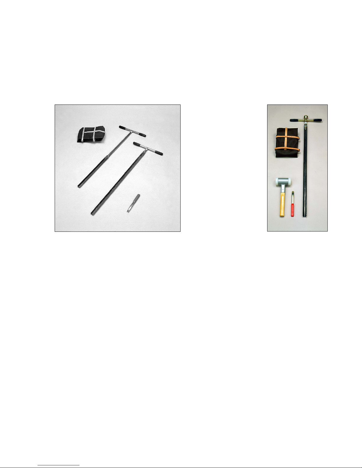
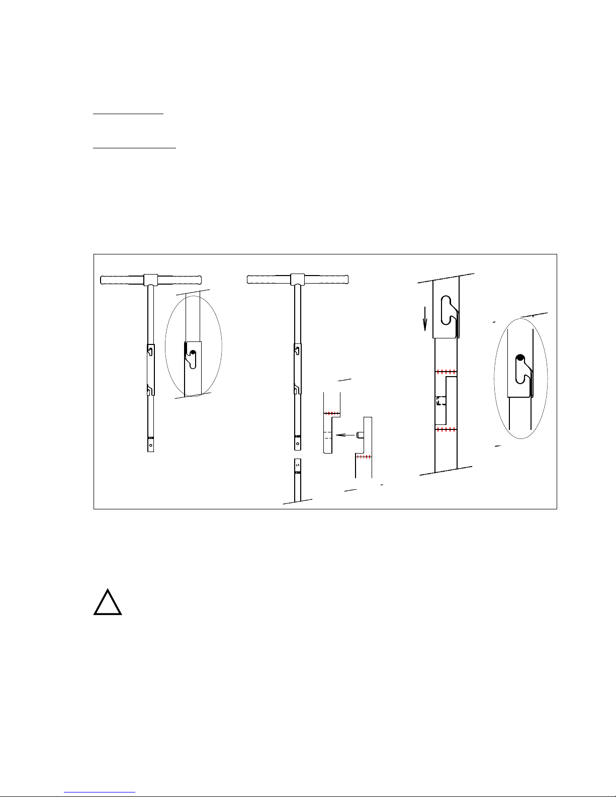
1.2 Single gouge auger set for more or less soft soils
Thesinglegougeaugersetformoreorlesssoftsoils(left-handgure)consistsoftworegularsinglegougeaugers
(1, 2), a bent spatula (3) and a carrying bag (4). The set is suitable for use in softer soils such as peat, clay and
sandy or disturbed soils.
Both augers measure 110 cm; their operational depths are 50 (1) and 100 cm (2) respectively. The upper part has
rubber grips.
1.3 Single gouge auger set for hard soils
Thesinglegougeaugersetforhardsoils(right-handgure)consistsofagougeaugerwithaheavy-dutyauger
body (1), an impact-absorbing steel hammer (2), a bent spatula (3) and a carrying bag (4). The set is suitable for
use in harder soils such as dry soils or soils containing debris.
The auger’s body has an operational depth of 100 cm and has a beating head welded onto it. The upper part has
rubber grips.
Thesteelhammerisimpact-absorbing;itsheadcontainsleadbulletsowinginthedirectionofthestrokeupon
impact. Its nylon cups prevent damage to the gouge auger.
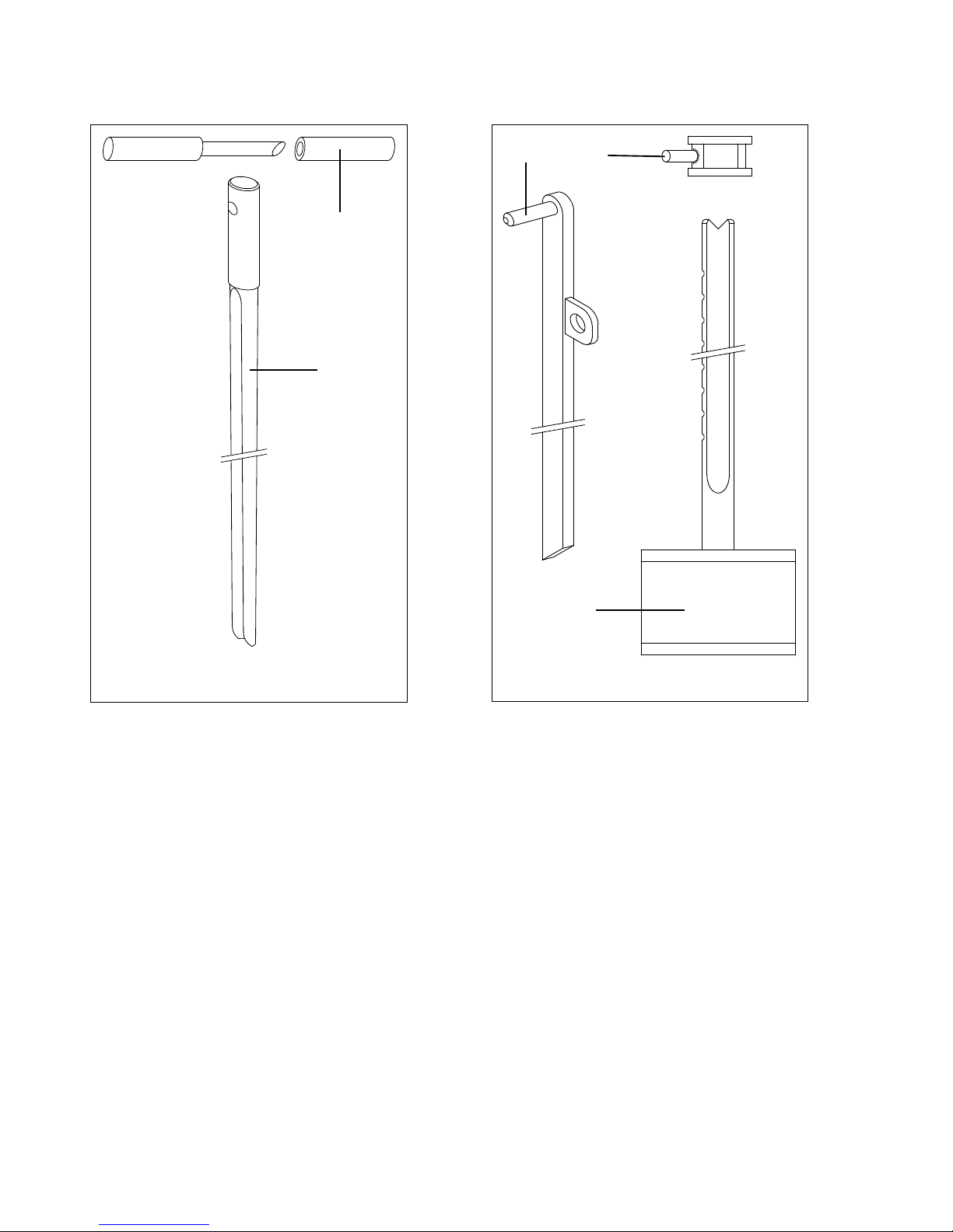
1.4 Single gouge auger set for very hard soils
The single gouge auger set for very hard soils consists of a gouge auger, Purckhauer type, a gouge auger pulling
set with hammer, a bent spatula and a carrying bag. The set is suitable for use in very hard soils such as stiff loam
and soils containing debris.
ThePurckhauergougeauger’soperationaldepthis100cmandithasan18-mminsidediameter(seeleftgureon
page 4). The outside diameter varies from 25.5 mm at the bottom end to 30 mm at the top end. Its conical shape
causes the gouge auger not to have too much frictional resistance of the soil. The top end has an opening for in-
sertion of either the grip or the lever. The grip (2) has two telescoping parts. The tip of one of the halves is slanted
and can be used to remove the soil sample.
Single gouge auger set
for more or less soft soils
(left)
Single gouge auger set for
hard soils (right)
4
Thesolidnylonhammer(3)isnotimpact-absorbing,itshandlehasindentationsatxeddistancesanditcanbe
used to:
pound the Purckhauer gouge auger.
withdraw the auger with the lever.
The gouge auger pulling set consists of a lever (5), a square ring (4) and a nylon hammer (3). The lever is a metal
bar with an eye and a pin. One end of the bar is slanted to allow removal of the sample.
The square ring has a pin welded onto it at a 45° angle. The ring is slid over the hammer handle and caught in
anindentation,theeyeontheleveristtedoverthepinandtheleverisnowinpositiontowithdrawthegouge
auger (see paragraph 5.3).
1.5 Bi-partite gouge auger for more or less soft soils
The bi-partite gouge augers for more or less soft soils both consist of six bottom parts with various auger bodies,
anupperpartwithagrip,extensionrods,Edelmanaugercombinationtype,apush/pullhandleandvariousacces-
sories. A set of bayonet connections (see picture, page 1) is available, as well as one with conical thread connecti-
ons. Both sets are suitable for softer soils such as peat, clay, and sandy or disturbed soils.
Auger bodies are available with either a 50-cm or a 100-cm operational depth, each with three different diame-
ters: 20, 30 and 60 mm. The choice of type of auger depends on the type of soil, and on its use (see 6. Applicati-
ons).
1
2
Purckhauer gouge auger (1) with grip (2)
54
3
Gouge auger pulling set consisting of nylon
hammer (3), a square ring (4) and a lever (5)
4
5
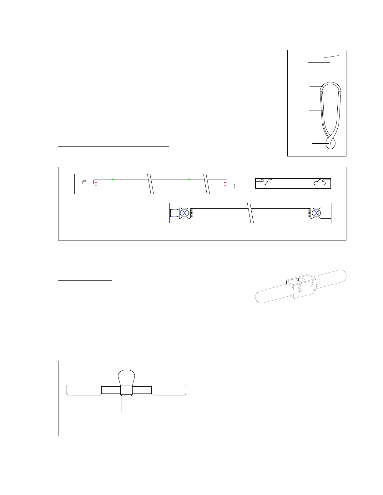
The Edelman auger combination type.
The Edelman auger body is conical in shape and consists of two blades (1) joined in a bit
(2). The top of the blades is welded to a bracket (3), which is connected to the auger rod
(4)(seegure).Thebladesarevaultedandwhenenteringthesoilthesampleisdugup
and evenly guided into the inside of the auger body. The vaulting of the blades not only
promotesdiggingupbutalsoensuresarmgripofthesamplewhilepermittingeasy
emptying of the auger body.
The Edelman combination type auger’s diameter (measured diagonally between the bla-
des at the broadest part of the auger body) measures 7 cm, the blades measure 35 mm
in width. This permits a good hold of moderately cohesive soils, while cohesive soils can
easily be removed.
Upper part, extension rods and connections.
The upper part measures 60 cm and has a detachable, synthetic grip. The extension rods
measure 1 m. A total length of 5 m can be achieved by linking the extension rods.
Thetailendsoftheextensionrodsarehalf-cylindricalandarettedwitheitheraneyeorapin.Theeyeandthe
pin lock into each other and are secured by a coupling sleeve. The extension rods with conical thread connections
can be attached using a spanner.
ThePush/PullHandle.
Thepush/pullhandlehastwopartsthatcanbettedaroundarod.Once
pressure is exercised on the two bars of the handle its construction ensures
armholdoftherod.
1.6 Bi-partite gouge auger set for hard soils
The bi-partite gouge auger set for harder soils consists of an upper part with beating head, a gouge auger with
heavy-duty auger body, a steel hammer, an Edelman combination type auger, extension rods and various accesso-
ries. The parts in this set have conical thread connections. The set is suitable for use in hard soils such as dry soils or
soils containing debris.
The gouge auger’s operational depth measures 100 cm
and has a 30-mm diameter (compare the single gouge
auger for hard soils in paragraph 1.3).
The upper part with beating head measures 10 cm to
ensure a proper operating position and stability.
1
3
4
2
Short upper part with beating head (conical thread)
Extension rod with bayonet connection
and coupling sleeve (above)
Extension rod with conical thread
connection (below)

6
2. Technicalspecications
The table below lists the dimensions of various augers. The Edelman combination type auger’s diameter is measu-
red diagonally between the blades at the broadest part of the auger body!
Gouge auger set Auger type Operational
depth (cm)
Diameter (mm)
Single, soft soils Standard gouge auger 50, 100 cm 30
Single, hard soils Heavy duty gouge auger with beating head 100 30
Single, very hard soils Purckhauer gouge auger 100 Outside: 25.5 - 30
Inside: 18
Bi-partite, soft soils Standard gouge auger
Edelman auger
50, 100 20, 30, 60
70 (blade width: 35)
Bi-partite, hard soils Heavy duty gouge auger
Edelman auger
100 30
70 (blade width: 35)
The auger bodies are made from iron-manganese steel (not stainless, non-toxic). All auger bodies are unpainted for
the purpose of environmental research.
3. Safety Instructions
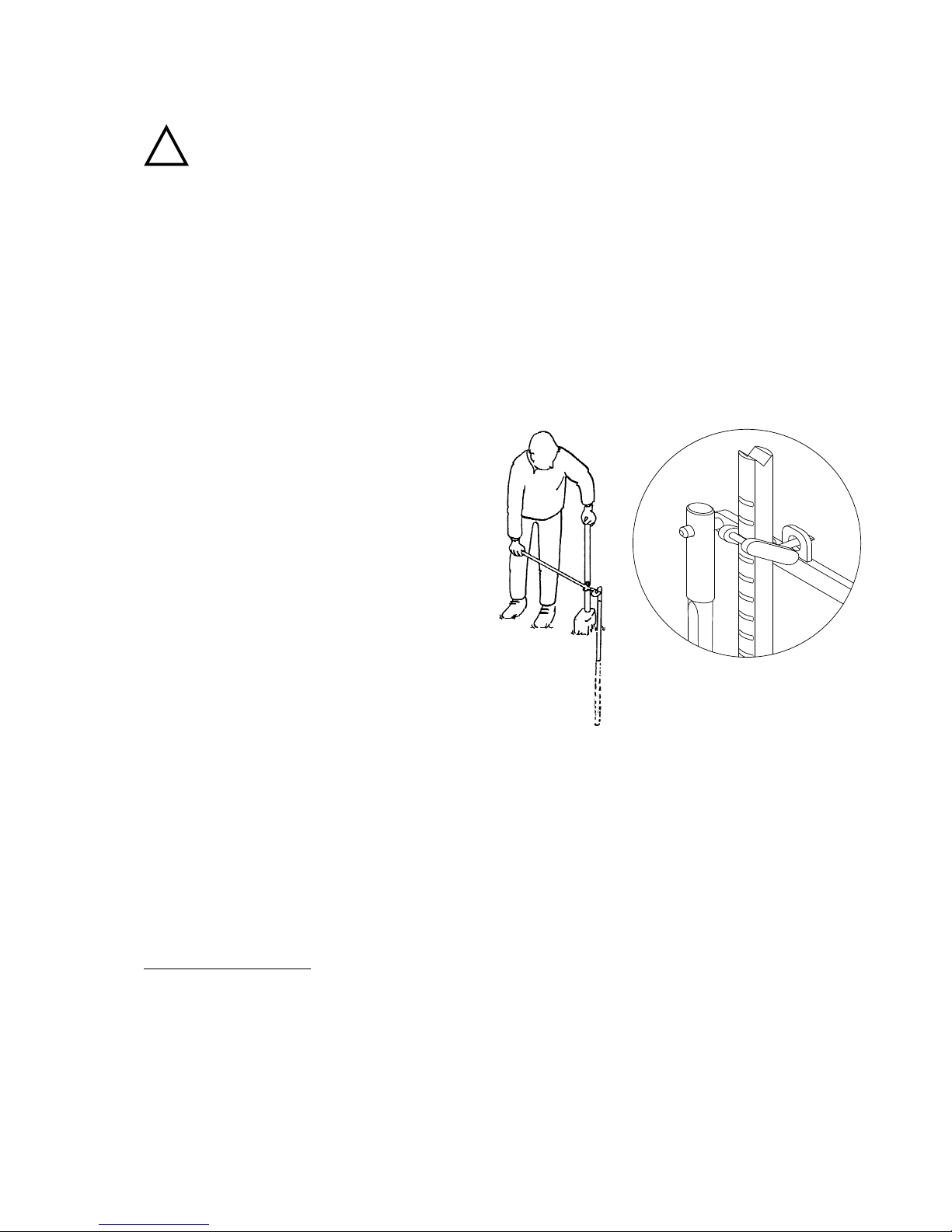
Hold the coupling sleeve of bayonet connections in the middle, this will prevent you from
catching the skin of your hands between the parts while (dis)connecting them.
To withdraw the auger keep your back straight and your knees bent to prevent injuries.
Empty the gouge auger with a spatula. Make sure not to touch the cutting edges; they are
very sharp. Inappropriate use may cause you to cut your hands.
Fill the borehole with soil or special bentonite plugs after augering. This will prevent humans
or animals to trip into the hole and incur injuries. In addition, it will allow impermeable soil
layers to recover.
Becautiousduringathunderstorm.Lightningstrokesoftenoccurintheopeneld,inparticu-
lar when holding a metal auger.
Do not force, or pound on, the auger. Pounding may cause serious damage, such as cracks or
snapped joints. Forcing may distort the auger body.
When using heavy-duty gouge augers, always utilise the impact-absorbing steel hammer if
force is necessary. This is safer and will prevent damage to the auger. Avoid using standard
metal hammers. This may cause damage to the auger and a bouncing hammer may lead to
injuries.
While augering, hold the auger by its synthetic handle. It is fully insulated should you hit an
electricity cable.
Augers over 4 m. should be handled in parts. This will prevent damage to the rods and reduce
the risk of being hit by augers tipping over. This applies to inserting and hoisting the auger.
!
!
!
!
!
!
!
!
!
6
7
4. Preparing for use
Single auger sets:
Depending on the type of soil select an appropriate gouge auger (see 6. Applications).
Bi-partite auger sets:
1. Bayonets:Uponrstuse,detachthecouplingsleevesfromtheextensionrodsandtheupperpart.
2. Screw the handle into the upper part.
3. Select an appropriate auger, depending on the type of soil (see 6. Applications).
4. Link the bottom part with auger body to the upper part. Use a spanner to connect the parts with a conical
thread.Forbayonetconnections(seegure):
4.1 Hold the coupling sleeve in the middle and slide it onto the upper part until it clicks on the nipple (step 1).
The sleeve is locked when it cannot be rotated.
4.2 Hook the upper part to the bottom part (step 2)
4.3 To lock the connection, unscrew the sleeve from the upper part, and slide it across the connection (step 3)
and click it onto the nipple (step 4). Check the lock. Notice it will have a slight play.
Hold the coupling sleeve in the middle, this will prevent you from catching the skin of your
hands between the parts while (dis)connecting them.
Connecting the auger parts
1 2 4
3
!
8
5. The use of gouge augers
5.1 Single gouge augers for more or less soft soils
1. Push the gouge auger vertically into the soil without rotating it. Take a sample with a maximal length equal to
the operational length of the auger.
2. Cut off the sample by rotating the auger.
Rotating the auger with sample facilitates hoisting and prevents loss of sample. Cut off the
sample by rotating the auger a full circle without pressing down.
3. To withdraw the auger after sampling, pull it upward gently while rotating it. Rotating will prevent loss of sam-
ple and counterbalance the underpressure below the auger.
Keep your back straight and your knees bent to prevent injuries when hoisting the auger.
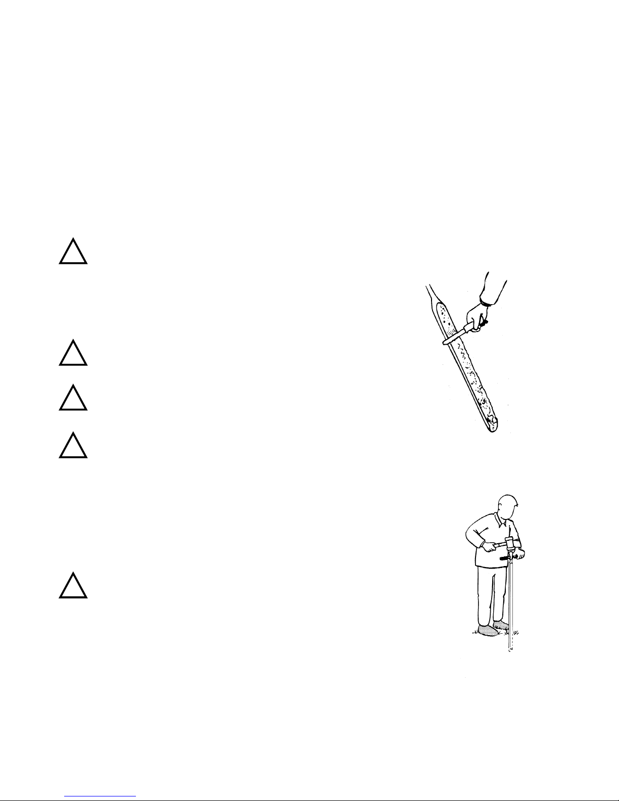
4. Use a bent spatula to cut off protruding soil along the auger’s cutting edges, this
willprovideanalmostcylindrical,undisturbedprolesuitableforinvestigationor
sampling.
5. Push out the sample using the rounded side of the spatula.
Empty the gouge auger with a bent spatula. Make sure not to touch
the cutting edges; they are very sharp. Inappropriate use may cause
you to cut your hands.
Fill the borehole with soil or with special bentonite plugs after au-
gering. This will prevent humans or animals to trip into the hole and
incur injuries. In addition, it will allow impermeable soil layers to
recover.
Be cautious during a thunderstorm. Lightning strokes often occur in
theopeneld,inparticularwhenholdingametalauger.
Remarks:
Shouldyouencounterconsiderableverticalresistance,thenhorizontalresistancemayoc-
cur as well. This may cause torsion of the auger body, especially when working at a greater
operational depth. It will help to revolve the auger occasionally without pressing down.
Donotdothistoofrequently;thesamplemayloseitsrmness,andlossof
sample may occur. In harder soils you may opt for shallower sampling.
Do not force, or pound on, the auger. Pounding may cause serious damage,
such as cracks or snapped joints. Forcing may distort the auger body.
Soil types may vary, necessitating the use of different types of augers (see 6. Applications)
5.2 Single gouge augers for hard soils
1. Position the gouge auger with heavy-duty auger body vertically on the ground and hold the
handle with one hand.
2. Use the impact-absorbing steel hammer to drive the gouge auger into the soil. Used properly, this hammer is
safe and will not cause the sample to fall apart. Take a sample of maximally 110 cm.
!
!
!
!
!
8
9
Always utilise the impact-absorbing steel hammer if force is necessary. This is safer and will
prevent damage to the auger. Avoid using standard metal hammers. This may cause damage to
the auger and a bouncing hammer may lead to injuries.
3. Cutting, hoisting and sampling take place as described as in paragraph 5.1.
5.3 Single gouge auger set for very hard soils
1. Attach the handle to the Purckhauer gouge auger, insert the gouge auger several centimetres vertically into the
ground and remove the handle.
2. Drive the auger into the ground using the steel hammer with nylon head to a depth of your choice (maximally
100 cm). Re-attach the handle to the auger.
3. Cut off the sample by rotating the auger a full circle without pressing down. Remove the handle again.
4. Use the gouge auger pulling set to withdraw the gouge auger:
4.1 Rest the hammer on its head, the indentations
on the handle facing the gouge auger.
4.2 Slide the square ring over the handle. Put the
eye on the lever over the pin on the square
ring, and insert the lever’s pin into the hole in
thetopendofthegougeauger(seegures).
The pin on the square ring now functions as
the axis of leverage.
4.3 Hold the hammer’s handle with one hand and
push the lever down with your other hand.
This will pull the auger up.
4.4 Lift the lever slightly to allow the ring to slide
some indentations up for full withdrawal of
the auger.
5. Empty the auger with sample using the bent
spatula. Use the whetted end of the handle or the
bottom end of the hammer’s handle.
5.4 Bi-partite gouge auger sets
Usage of the bi-partite gouge augers is similar to that of single gouge augers. See paragraph 5.1 for usage of
gouge augers for soft soils, and paragraph 5.2 for hard soils.
Differences:
Bi-partite gouge augers can be operated at greater depth.
Bi-partite gouge augers can be extended when augering over 1.20 m, using one or more extension rods.
Bi-partite augers over 4 m are hoisted and inserted in smaller parts.
Thebi-partitesetsconsistofapush/pullhandleandanEdelmancombinationtypeauger.
The bi-partite gouge auger sets for soft soils permit incremental augering.
Augering at greater depth.
The bi-partite sets are suitable for augering up to a depth of 5 m. Bear in mind that:
Frictional resistance tends to increase when augering at greater depth, using a same diameter. A combination
of suction (when hoisting the auger) and weakness of the soil causes the borehole to be more tight. This can be
solved by honing the borehole after two augerings (depending on the situation). Rest the auger on the bottom
of the borehole and hoist it while rotating.
Anextendedaugershouldalwaysbepresseddowninaxedposition.
!

10
Alwaysinserttheaugerholdingitinaxedposition,forexamplewiththeroundedsideof
the blade towards you. This will allow you to easily drive the auger through the auger hole
When a moderately cohesive layer precedes a cohesive layer, use an Edelman auger before augering.
To allow working in a comfortable position, Eijkelkamp Agrisearch Equipment also has 25- and 100-cm upper
parts available.
Attaching the extension rods.
Bayonet connections: slide the sleeve upward and lock it onto the upper part. Unclamp the upper and bottom
part. Take an extension rod and a coupling sleeve. Click the sleeve into position on the bottom end of the exten-
sion (the end with a hole). Attach the upper and bottom part to the extension. Make sure the coupling sleeve is
put well into position!
Attach extension rods to the upper end of the gouge auger, directly below the upper part. The
rods tend to bend and are followed by the line of the auger hole.
An auger over 4 m should be inserted and hoisted in parts:
Handle the auger in parts. This will prevent damage to the rods and reduce the risk of being
hit by augers tipping over.
1. Hold the bottom part of the auger in the borehole while it comes out for approximately 50 cm. Grip the bot-
tompartrmlytopreventitfromdroppingintotheaugerhole.
2. To detach: unclamp the upper and bottom part. Bayonets: slide the sleeve upward and lock it onto the upper
part.
To connect: clamp the two parts. Bayonets: slide the sleeve down from the upper part across the connection and
lock it onto the bottom part of the auger.
Make sure to reconnect the parts in the same order. The rods tend to bend and are followed by
the line of the auger hole.
Push/pullhandle.
In the case you need to withdraw the auger and the handle’s position is not comfortable to hold,
usethepush/pullhandle(seegure).Thepush/pullhandleisidealforinsertionorwithdrawalof
the auger without straining your back. It is clamped around the extension rods at
any desired height.
Thepush/pullhandlemayalsobeoperatedbytwopersons.Tothatpurpose,clampthehandle
perpendicularly to the direction of the auger’s top handle. Face the other person holding the bars
ofthepush/pullhandlewithyourrighthandandholdingthebarsofthetophandlewithyour
left hand exerting up-or downward pressure.
The Edelman auger combination type.
The Edelman auger is utilised to auger a moderately cohesive layer, or to enlarge the auger hole
to reduce friction when augering.
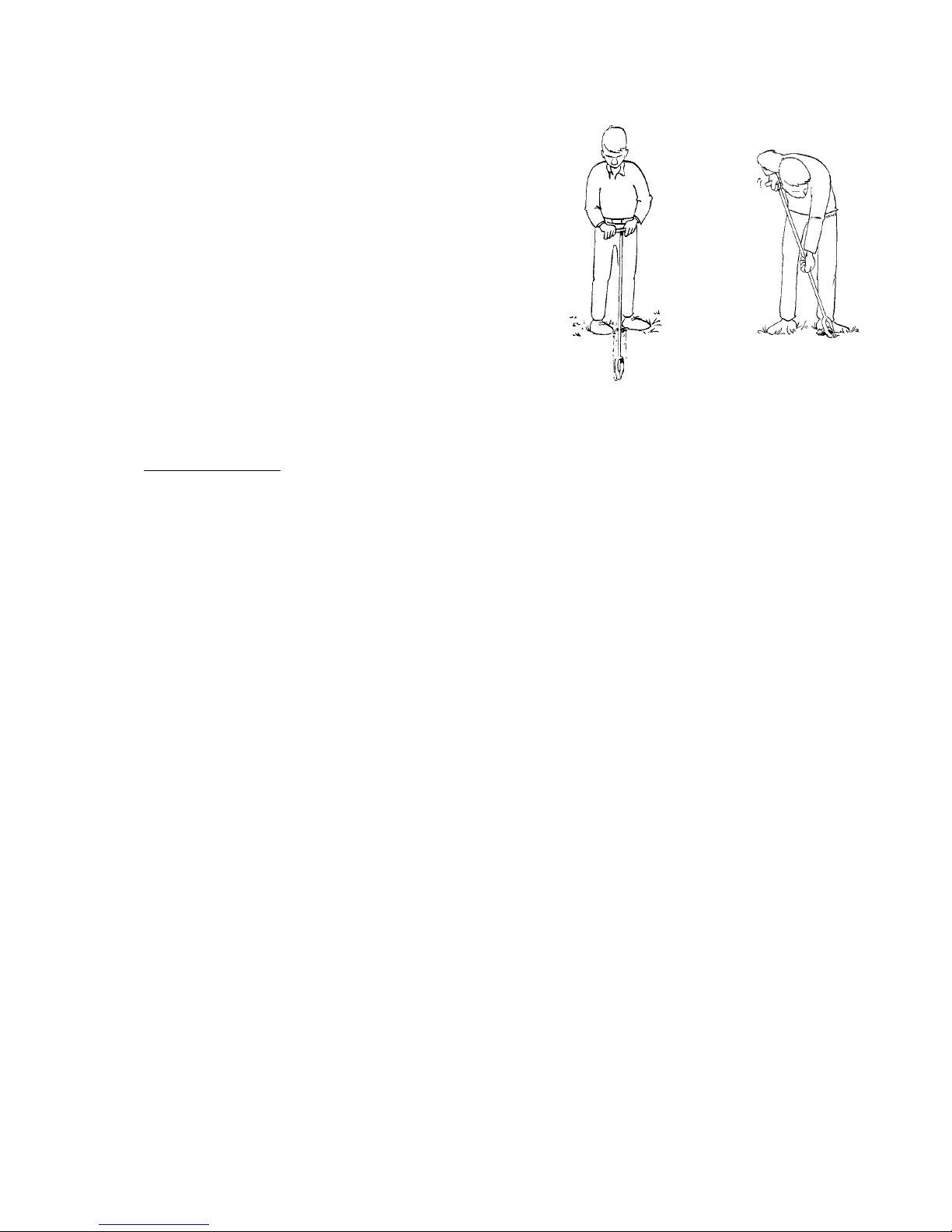
1. Holdtheaugerbyitshandleandrestitverticallyontheground(seegure,nextpage).
2. Upon2¼rotationstheaugershouldhavedug10cm.Theaugerbodywillbelleduptoits
bracket with slightly disturbed soil material. Depending on the type of soil additional rotations
may be necessary.
Always rotate an auger clockwise!
!
10
11
3. Cut off the sample and hoist the auger while gently rotating
it.
4. To release the cohesive material hold the auger askew on
thesurface(seegure),rotatetheauger180°whilepress-
ing it into the ground. The sample should detach itself and
can be taken out by hand or by lightly tapping the auger.
Moderately cohesive material will detach itself immediately.
Now, examination is possible.
Caution:
Donotoverlltheaugerbody.Superuousmaterialwillcoat
the auger hole, which hinders pulling out subsequent soil
samples.Whenaugeringunderthewatertableanoverlled
auger acts like a plunger, which hampers hoisting the auger
and results in loss of sample material.
Prevent the loss of sample material. Hoist the auger with sample while lightly rotating it, do not pull it straight
out.
Incremental augering.
Frictional resistance tends to increase when augering at greater depth using a same diameter. Consequently, the
auger hole needs honing. To reduce friction use the bi-partite gouge auger set for softer soils to carry out an incre-
mental augering. In this process two or three auger diameters are being used:
1. Pre-auger, using a 60-mm gouge auger
2. Continue, using a 30-mm gouge auger
3. If necessary, use a 20-mm gouge auger for sampling prior to continue with other types of augers. Empty the
auger using a narrow, bent spatula. Auger the same hole again, using a 30-mm or 60-mm gouge auger. The
diameter of the extension rods do not permit augering at greater depth with a 20-mm gouge auger.
6. Applications
Gouge augers are used in cohesive soils. The standard types are suitable for use in soils with little or moderate
penetrating resistance. For hard soils gouge augers have been developed with a heavy-duty auger body and a be-
ating head. They are driven into the soil using a special impact-absorbing hammer. For very hard or stony soils the
Purckhauer gouge auger is ideal. It is driven into the soil using a heavy nylon hammer and hoisted with a special
pulling set.
The gouge auger sets for soft soils consist of gouge augers with auger bodies of different operational depths and
diameters. The optimal operational depth depends on the penetrating resistance of the soil, type of soil, and au-
gering depth. The longer the auger body, the more susceptible the auger will be to torsion. It is recommended to
use a short auger body in hard soils. The optimal diameter depends on the composition and structure of the soil,
aswellasontheresearchobjectives.Asarule,ne-grainedorpackedsoilsdemandasmallerdiameterthanloose
soils.
The choice of type of connection depends on the purpose of the job at hand.
Since gouge augers produce hardly disturbed samples, they are often used in:
Surveying
Soil assessments
Education
Rootage surveys
Fertiliser research
Clay-inventories
Paleontological research

12
The tables below list various applications of gouge augers and different types of connections for bi-partite augers.
Set Applications
Single gouge auger sets Pedological research of surface layers in cohesive soils;
to obtain minimally disturbed samples with a wide
proelrange.
Bi-partite gouge auger sets Pedological research in cohesive soils up to a depth of
5 m; to obtain minimally disturbed samples with a wide
proelrange.
Type of auger Applications
Standard gouge auger, operational depth 50 cm Soils with moderate penetration resistance; short pro-
lerange
Standard gouge auger, operational depth 100 cm Soilswithlowpenetrationresistance;longprolerange
Standard gouge auger, diameter 20 mm Soils with low penetration resistance; incremental au-
gering with sampling
Standard gouge auger, diameter 30 mm Soilswithlowpenetrationresistance;nalstageof
deeper, incremental augering
Standard gouge auger, diameter 60 mm Soils with low penetration resistance; initial stage of
deeper, incremental augering
Heavy-duty gouge auger (with beating head) Soils with strong penetration resistance; soils contain-
ing debris
Purckhauer goge auger Soils with very strong penetration resistance; stony soils
Edelman auger combination type, diameter 7 cm Pre-augering in moderately cohesive soils; honing to
reduce frictional resistance
Type of connection Applications
Bayonet Easy connection, ideal for augering at greater depth
Conical thread Rigid connection (no play), suitable for pounding or for
perfectly straight auger holes
7. Troubleshooting
Soil particles between the augering rod and the coupling sleeve have caused the sleeve to jam. Pour clean
waterinonedirectioninthesleeve,thiswillushouttheparticles.Holdthespatulabythebladeanduseits
synthetic backside to tap the sleeve, coarse particles will come loose, thereby allowing the sleeve to slide. In
winter conditions, icing up may cause the sleeve to jam.
Augering is strenuous; the auger does not screw well into the soil. Take a short sample and cut it off. When
augering at greater depth, make sure to hone the auger hole between samples. In stiff soils, use a heavy-duty
gouge auger. Pre-auger, using the Edelman auger, in hard and non-cohesive soils. When using the bi-partite set
for soft soils, incremental augering may be carried out.
Loss of sample during augering. This may be caused by prematurely cutting off the sample, which leads to
reduced cohesion. Take a shorter sample. Loss of sample may also be caused by changing soil types (encounte-
ring moderately cohesive soils).

12
13
Bayonets: make sure not to lose the coupling sleeves. Count them after augering. Carry them attached to an
extension rod or to an upper part. Always check whether the sleeves are locked. Two spare sleeves are provi-
ded.
The conical thread connections are hard to loosen. Keep the thread clean to ensure easy movement. Use span-
ner 20x22.
Oxidation of the augers in the carrying bag. Dry the equipment before stowing; the carrying bag does not brea-
the.
8. Maintenance
It is recommended to keep the augering equipment in good condition by rinsing it during use. Use a stainless
steel brush to clean the conical thread connections.
Clean the augers after use with running water. Take off the coupling sleeves from the rods and the upper parts,
clean and dry them well to keep the insides smooth and prevent oxidation (rough inner surfaces of the sleeve
may cause it to jam). Stow away the equipment in the carrying bag after drying.
The auger bodies need no whetting, use keeps them sharp-edged. Under normal conditions oxidation is not
detrimental to the auger and will vanish upon use.
Nothinginthispublicationmaybereproducedand/ormadepublicbymeansofprint,photocopy,microlmoranyothermeanswithoutprevi-
ous written permission from Eijkelkamp Agrisearch Equipment.
Technicaldatacanbeamendedwithoutpriornotication.
Eijkelkamp Agrisearch Equipment is not responsible for (personal damage due to (improper) use of the product.
Eijkelkamp Agrisearch Equipment is interested in your reactions and remarks about its products and operating instructions.

14
Appendix: Rust on augers and gouges
These augers and gouges are made of high tensile-strength forgeable iron-manganese steel. Both iron and man-
ganese are non-toxic metals, abundant in the earth’s crust on which we live. Natural concentrations are very high.
Duringstorageandtransportsomerustmaydeveloponthebaremetalsurface.Duringrstusethisrustwillscour
offquickly.Youmayalsoscourwithsomewetsandpriortorstuse.Theaugerorgougeisthenreadyforsam-
plingofsoilonallmetalslikezinc,cadmium,chromium,copperandevenironandmanganese!
Question 1: How do I clean and maintain my augers / gouges?
In practice augers keep themselves clean (and sharp) by the high friction of soil particles rubbing the augers
surface. Augers or gouges used in acid, saline or alkaline soil are prone to oxidation and should be rinsed with
pH neutral water after use. After a drilling in an oil-polluted borehole you may clean the auger with a brush in a
bucket with water with neutral baby-shampoo added. Spraying our detergent 20.05.29 is very effective too and
willalsomobilizetrace-metals,eventhezincplatingfromtheextensionrods!Usethisdetergentwithcareorlimit
theusetostainlesssteelorplastictoolsonly.Isopropylalcoholonatissueisneforrapidon-sitecleaning.Acetone
is more effective and will even remove tars from metals. Dismantle coupling sleeves and other loose parts prior to
cleaningtoallowrapidandcompletedryingafterthenalwaterrinse.Storeinawellventilatedareafreefrom
dust and, for plastic materials, smells.
Question 2: Why did we not prevent the development of natural rust?
A paint will blister off quickly and will pollute samples with a variety of organic pollutants during a prolonged pe-
riod,necessitatingadifcultandcumbersomecleaningprocedurepriortorstuse.
Azincplatingisverysoft.Thezincwillbescratchedoffinafewdozensofdrillingsresultinginmeasurablequanti-
tiesofzincinyoursoilsamplesandinuencingyourmeasurementsduringaprolongedperiod.Afterafewdaysor
weeksthezinchascompletelydisappearedandisnoteffectiveanymore.
Awaxorgreaseiseasytoputon,butfairlyhardtoremoveand,again,risky.Greases,oilsandwaxeswillinu-
ence a gas chromatogram (GC) made from soil samples taken with such an auger or gouge. In addition the layer
is sticky and it is unavoidable that it will spread all over in carrying bag or case, extension rods, gloves and conse-
quently soil samples. This should be avoided at all times.
Question 3: The extension rods and upper part are zinc plated. Does this zinc plating contaminate the
soil sample?
No,sincethereisnointensescouringcontactbetweensoilsampleandtherodsthereisnoinuence.
Question 4: Do stainless steel soil samplers (coring tubes and rings) contaminate soil samples?
Stainless steel is an alloy of high percentages of mainly chrome, iron and nickel. Alloys have characteristics that are
different from the characteristics of a simple “mix” of these metals! Stainless steel is so chemically stable that no
loose oxides are formed. It is also hard; scouring with soil will not lead to detectable levels of iron, chromium or
nickel concentrations in soil.
Question 5: Does the chromium plated gouge Model P (04.03) contaminate a soil sample?
This gouge is plated with a pure thick layer of nice shining chromium. Chromium is an extremely hard metal and
will only and partly be rubbed off in years of use! Although there is very little chance that these quantities will
contaminateasamplewithChromiumwewouldnotrecommendthisgougeasrstchoiceforsoilanalysison
chromium.
This manual suits for next models
1
Table of contents
Popular Lawn And Garden Equipment manuals by other brands

Forest garden
Forest garden FGFSSCV2 quick start guide

Rowlinson Garden Products
Rowlinson Garden Products Eaton Summerhouse 7x5 Assembly instructions

P3 International
P3 International Sol Mate P7909 Specifications

Black Flag
Black Flag BZ-20 owner's manual

Dolmar
Dolmar EV-3618 Original instruction manual

Volpi
Volpi KV81 user manual


