manuals.online logo
Brands
  1. Home
  2. •
  3. Brands
  4. •
  5. Eiki
  6. •
  7. Projector
  8. •
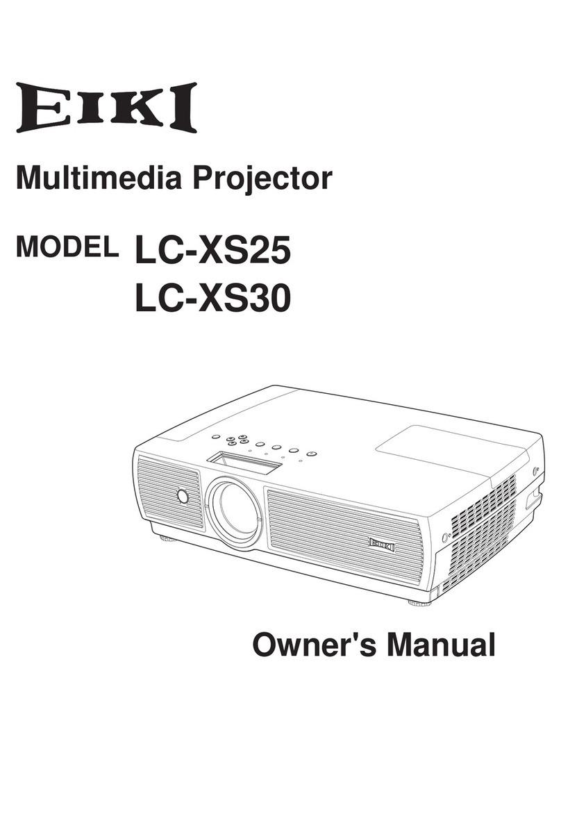
  9. Eiki ELF N Series User manual

Eiki ELF N Series User manual

This manual suits for next models

1

Other Eiki Projector manuals

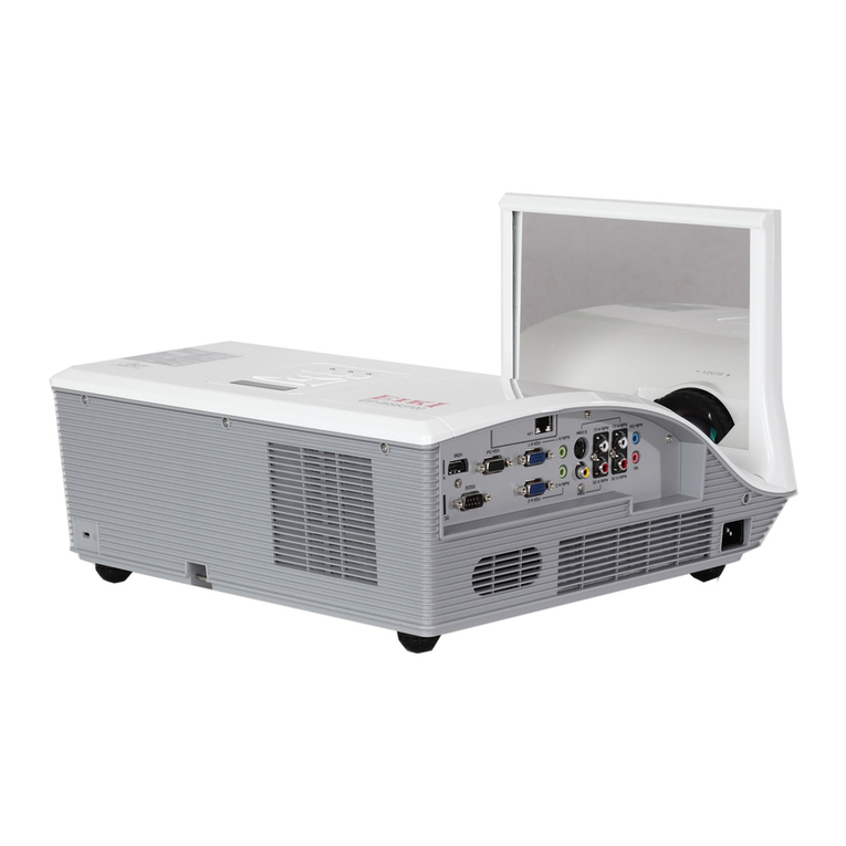
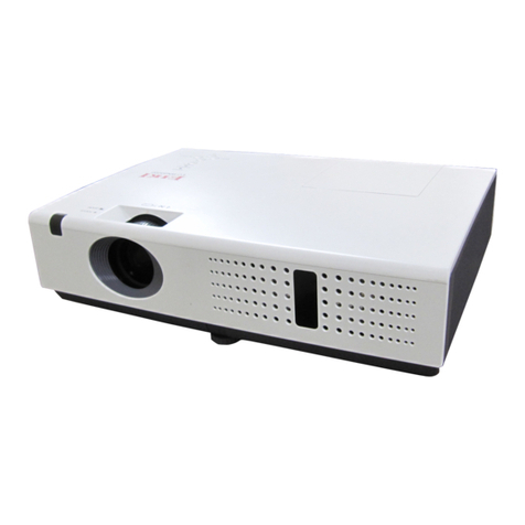
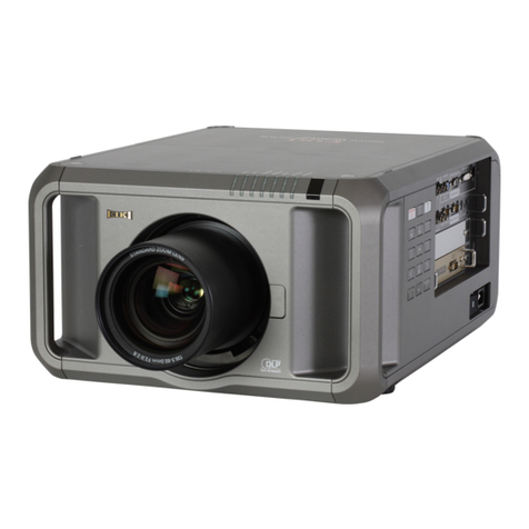
Eiki EIP-D450 User manual

Eiki

Eiki EIP-D450 User manual

Eiki EIP-2500 User manual

Eiki

Eiki EIP-2500 User manual

Eiki LC-5000U Setup guide

Eiki

Eiki LC-5000U Setup guide

Eiki LC-XG250L* User manual

Eiki

Eiki LC-XG250L* User manual

Eiki LC-XNS2600 User manual

Eiki

Eiki LC-XNS2600 User manual

Eiki EK-400X User manual

Eiki

Eiki EK-400X User manual

Eiki EK-130U User manual

Eiki

Eiki EK-130U User manual

Eiki LC-XGA980U Setup guide

Eiki

Eiki LC-XGA980U Setup guide

Eiki LC-XBM21 User manual

Eiki

Eiki LC-XBM21 User manual

Eiki LC-XB33 User manual

Eiki

Eiki LC-XB33 User manual

Eiki XGA Brilliant LC-XB100 User manual

Eiki

Eiki XGA Brilliant LC-XB100 User manual

Eiki LC-WB42N User manual

Eiki

Eiki LC-WB42N User manual

Eiki LC-XBS500 User manual

Eiki

Eiki LC-XBS500 User manual

Eiki LC-WGC500 User manual

Eiki

Eiki LC-WGC500 User manual

Eiki LC-SM2 User manual

Eiki

Eiki LC-SM2 User manual

Eiki LC-XGA980E Setup guide

Eiki

Eiki LC-XGA980E Setup guide

Eiki LC-HDT700 Installation and operation manual

Eiki

Eiki LC-HDT700 Installation and operation manual

Eiki PLC-XU101 User manual

Eiki

Eiki PLC-XU101 User manual

Eiki EK-600LU User manual

Eiki

Eiki EK-600LU User manual

Eiki LC-XGA970U Setup guide

Eiki

Eiki LC-XGA970U Setup guide

Eiki LC-WXL200 User manual

Eiki

Eiki LC-WXL200 User manual

Eiki WS250 User manual

Eiki

Eiki WS250 User manual

Eiki LC-XG250 User manual

Eiki

Eiki LC-XG250 User manual

Eiki LC-NB3E User manual

Eiki

Eiki LC-NB3E User manual

Popular Projector manuals by other brands

InFocus LitePro 610 quick start

InFocus

InFocus LitePro 610 quick start

Epson EH-TW5900 datasheet

Epson

Epson EH-TW5900 datasheet

FOREVER MLP-100 manual

FOREVER

FOREVER MLP-100 manual

Toshiba TDP-MT8U Specifications

Toshiba

Toshiba TDP-MT8U Specifications

Mitsubishi XD500U specification

Mitsubishi

Mitsubishi XD500U specification

Kodak Ektapro 3020 Illustrated parts list

Kodak

Kodak Ektapro 3020 Illustrated parts list

Toshiba TDP-EW25U Specifications

Toshiba

Toshiba TDP-EW25U Specifications

Barco iQ PRO G500 supplementary guide

Barco

Barco iQ PRO G500 supplementary guide

NEC Showcase Series HT1100 user manual

NEC

NEC Showcase Series HT1100 user manual

Philips LC1341 user guide

Philips

Philips LC1341 user guide

Epson PowerLite 1266 user guide

Epson

Epson PowerLite 1266 user guide

MAGINON DLP 1400S user manual

MAGINON

MAGINON DLP 1400S user manual

Toshiba TLP-380 owner's manual

Toshiba

Toshiba TLP-380 owner's manual

Philips PicoPix PPX2480/EU user manual

Philips

Philips PicoPix PPX2480/EU user manual

Hitachi CP-X605 Series Specifications

Hitachi

Hitachi CP-X605 Series Specifications

Optoma TW1692 user manual

Optoma

Optoma TW1692 user manual

Kodak EKTAPRO instruction manual

Kodak

Kodak EKTAPRO instruction manual

Optoma Optoma PRO150S datasheet

Optoma

Optoma Optoma PRO150S datasheet

manuals.online logo
manuals.online logoBrands
  • About & Mission
  • Contact us
  • Privacy Policy
  • Terms and Conditions

Copyright 2025 Manuals.Online. All Rights Reserved.

Film-Tech
The information contained in this Adobe Acrobat pdf
file is provided at your own risk and good judgment.
These manuals are designed to facilitate the
exchange of information related to cinema
projection and film handling, with no warranties nor
obligations from the authors, for qualified field
service engineers.
If you are not a qualified technician, please make no
adjustments to anything you may read about in these
Adobe manual downloads.
www.film-tech.com
EIKI/ELF N Series
L6mmProjector
ServiceManual
www.cineinfo.co.uk
www.cinephoto.co.uk
TAEI..E
OF gOFITEffiGi
Title FA6E
II{TRODUCTION
3l4-l: PRINCIPLES
OFOPERATIONS
l-l lntroduction. .. .. 15
l-2 MechanicalSystem ..-.-.t5
l-3 Electrical
System ... ." .. 15
l-4 Sound
System .-. ts
3l4-2; SERVICEPROCU,DURIjS
2-l Precautions.. .- .. 1?
2-2ToolsAndTestEquiprnent .....17
2-3 LubricantsAndLubricationCharts ...." Ig
24 TroubleslrootingHints .
3143: MODULE REMOVAL AND INSTALLATION
3-1CamTankModule... ...25
3-2AmplifierModule ........)<
3-3 MotarModule . .. 26-
3-4TransformerModule...- ...-...26
3-5 Lens
HolderAnd CateModule . . . 26
3144: MODULE REPAIRAND ADJUSTMENTS
4-l CamTankMsdule -. .
A. Specifications
B. Disassembly
C. Re-Assembly
D. Adjustments
LClawProtrusion ...-.-2&
S.ClawPositionAndFraming
..-. .....29
E.
ClawReplacement.... ........3u
F. ChangingShutterBlades -.......31
G. StillPictureClutch .....- j7
4-2 Amplifier Module
A. Specifications . . .- 33
B. PowerSupplyCircuit .,..33
C. AudioAmplifierCircuit ......,.i'
D. Magnetic
d"ecordAmplifier . . . . . . . . . .. . . : . .'. i;
E. AmplifrerCircuitDiagrams ----..i+
4-3 Motor Module
A- Specihcations
- - .- 39
B. MotarCircuifDiaersm ... 39
C. ConnectorWiringCode ...-.- .lg
D. SilentFilm Operation
Antl 50* 60HzConversion
.- . . . . +O
Transformer Module
TransforrnerCircuitDi*gram ---.41
ConnectorlViringCode .- --.-,- 41
LensHokler And GateModule
trilmGate
Assy. ........43
F-ilmShoeandLensHolderAssy
. ......43
314-5: CENERAL MECH.A,NICAL
SERVICINGAND ADJUSTMENTS
5-l Take-UpArm
A. kscription -. - --. 47
B. Adjustrnents...- ......-4j
"frl'$$rig*
27
11
21
2&
4-4
A.
B,
+s
A.
s.
-1-
TAEil.E
OF COfifGT*TS
PAGE
5-? SupplyArrn
A. Description... ...,$E
B. Adjustments,. ...49
5-3 ReverseProjection
A- Description.- -..-4g
B. Adjustments-. --.4g
54 Lower Loop SetterSystem
A- Descriptisn--. ...50
B. Adjustments--. ...50
5-5 S€lfThreadingFfiechanism
A. Descriptinn
.- .. ""52
B. Adjustments.... -..--.-55
l) +tSprocketshma*embly... .....55
2) *tFilmguide -._....55
3) Retraction
of theclaw . -- . ., 56
4l +ZFilmguide -......56
5) $ound drum rubber pinch roller . . . . .56
6) Tension.guideandrollerass€mbty
. . . -. -. .
ST
7, #2 $procket andshoeassembly . . . . .Sg
5{ Rewind Mechanism
A- Description-. ...,5g
B. Adiustments.... .......S9
5-7 Soundtrrum And Flywheel
A. Description-- ....59
B. Adjustments.... .-.....60
314{: SOUND
PICK-UP
SYSTEM
6-l Optical SoundFocusing
Procedure
A. Description.. ....61
B- Alignrnent-.. ...;-....61
l) Toolsandequipment.. .....61
2).Set-upprocedure -:.... -.,.61
3),Soundfocusadjustment. ....61
4)'Buzztrackadjustment. .....62
Magnetic
SoundPlaybackSystem
Description ..-...63
Alignment .-'.-..... .. -..-..6j
li. Toolsand.equipment
-. .....63
2I Set'up
procedure . -. .53
314-7:
LAMPCIRCUIT
?-l LampCircuit ...,65
A. Description-..- -..--...f5
B. Replacementandalignment.. ...65
314-8:ELECTRICAL
SYSTEM
8-1Electrical.$ystem .....; .,.....65
A. FunctionControlSwitch ...."..65
B. ElectricalCircuitDiagram .."....65
3r'4-9:SERVICE
UPDATES
ANEMODIFICATIONS
Attachment:CIRCUITDIAGRAMS ....-67 *79
"if" $giig
6:2
A.
B.
*2-
"il" $cfb
INTR,SDUCTION
I. This ServireManual
provides
thenecessary
lnf*rmx{i*ns for th* repair,
adiustrnent,
and
maintenrnee
of
ElKl NSTINT-*eriesplniectcrs,madelNST-0,
NST.I, NST"?,
NST.3,t{T"0,t{T-l, 8{T-?,
andNT-3,and
alsoEX-3000-frl
spriesexf,sprfr:r the Xerronlamp nuprply.
?' Thisrerviremanual
csntain $orne
part nurnbers
for csnveniencein identificatian'only"
When
ordrri*g
replac*rnenL
parts,
refrr to NST/NT rcpla*ement
parts
list.
3. ElKl NSTrrSl-1-tntinr
pr*ieclarsmayin the futuretreirnpr*vedor rno*lified.
Il'lodifiettions
made
afterthei*sue
of thismanual
will becover*d
by Service
Updates.
4. A coFy
of allof the perrinent
cliagrams
ar€attashed
at thecndof thi* rnanual.
5.CAUTION! Carernust
beexercised
to areoid
elm{rical
*hockwhileEeruieing
theproiector.
.-,
3.
SYMPTO[4
l. Pilot
lampnot0n
{t*ro$EffEs
rRouBLE $HoorING
I: ELECTRICAL
SYSTEM.
PROBABLE
CAUS€
1-
No power to the AC wall
outlet
2- Defective
power
cord
3. Faulty transformer sr con-
nection
4. Delectivepilot lamp
"lU"Series
CHART
REMEDY
1.Check
outlet
2.Check
& repairor replace
3. Repaircr replace
iSec
Sec
+41
4- Replace
1.Replace
or repair
{See
Sec4-3}
2.Check
& repair,
orreplace
{See
Sec4-3-C)
3. Check& rep'tace
{See
Sec,4-3}
4.Check
& adjust
(See
Sec
8-1-A)
5. Check& replace
{Sec
Sec
8-1-A)
6, Atlow motor to cool and
check
again.
1. Repface
lamp
2.
Check
& reseat
2. Re-position
andtighten
3.Check
andrepair
SecSec.5-1.,
& 5-3)
3-Pifot larnp on, motor
but the lampdoes
not
on in "forward lamp"
tion { {: rff }
2. Pilot lamp on, motor does
not runin "forward" position
{{F.q)
1-
Defectivemotormodule
2. Defectivcor openmotor con-
nections
3. Faulty motor capacitor
4-Switch cam not activating
microswitch#'l
5. Defectivemicro
switch
#1
6.'Motorthermalswitch
open.
(UL
& CSAtype)
J- LrE rTLLIYE rarf lP IrLtqtL
4-Defective
micro
switch
#4 or '
#5 on the function control
5. Open fr.ansfcrrnerconnection
6. Defective
transforrnermodule
1.Micro switch it? andlor *3
defective
2. Defective
motormodule
2- Looseswitch cam
3. Reverse ol take-up clutch
eann'sinstall$d
4. Pitqt lampon, motor runsin
"forward", but not in
"reYersc"
position
( tg; )
5..Function switch. does not
followtheindicated
sequence
1.Defective
famp
2. Lampnot seatcd
propsrly
thesocket
3- Defective
lamp
socket 3. Repair
or replacc
4-
Check& replace
{See
Sec8-l-A)
5,Check&:repair
{See
Sec
4-4-B)
6- Replacp
{See
Sdc
a-a)
1.
Check
or replace
{See
Sec8-1-A}
2. Replace
{See
Sec
4-3}
1.Loose
function switchknob 1. Re-lacateand tighten
runs
come
posi-
*it:
"t" $sries
SYMPTOM
6. #2 film guide{or self-thread
lever)
does
not setthe mecha-
nismto thread
7.
Leaderor film isdimpledin
the first few inchesbv the
spro.cket
teeth
II: SELF-THREADING
SYSTEM
PROBABLE
CAUSE
1-
Cam bracket.
is lsoseon the
#2 film guide
shaft
2.Main interlocking
bracketis
binding
or not latchingwith
the release
brackethook
REMEDY
1.Re-positionand
tighten
(See
Sec5-5-B4l
7. Check& adiust
(See
Sec5-5-B)
8.Leader
iams
guide in the #1 film
9. Tip of the leader enters
underneaththe inner guide
rail
10.Filmdoes
notthreadthrough
thegate,
and
jams
1
.Film is inserted
with the
sprccket holesoppositethe
sprocketteeth
2. Not enough clearancebe-
tween
the sprockel
plate
and
thefiim shce
3. Film path and #2 sprccket
drive
outof alignment
4. Film teader
too sofit
l. Film leadcr not trimmed
properly
2. Endof filmis
severely
curled,
..1
ortwrstedl
3.Verysoft'leader
4.+1 film guide
shaftloose
or
bent
5.Aperture
plate
assembly
rnis-
aligned.
-1.
Inner guiderail bent or nof
aligned
correctly
2. Loose
guidc
rail
screws
3. Film leader end severely
curled
or twisted.
1.Re-insertthe
film correctly
2.Check& adiust
(See
Sec5-5-81).
3.Check alignrnent.
of the ten-
sion
guide
rollers
(See
Sec5-5-86)
4. Check with anothcr fiIm
leader.
-l
.Trim and
repeatthreading
2. Straighten
andre-thread
3. R.eplaceleader
4. Re-align
andcheck.
(See
Sec5-5-82)
5. Rc-align
andchBck
{See
Sec
4-f }. ,
l. Afignor replace
(Sec
Sec
4-5)
2.Tighten
{See
Sec4-5)
3.Trim andre-thread
1.Film leader not trimmed
properly
2. Leadcr is severelycurled or
twisted,
or too soft
3-Too much t#'l film shoc
clearance
4. Dirty and obstrusted
garc
5. lnsufficientsidetravel
inner
guide
rail af the
6.Side pressure
spring
tension
too strong
7. Film shoe is not rctracted
during
threading
1.Trim
2.Trim, straightcn
or replace
3.Check& adiust
(See
Sec.5-5"81)
4-
Clean& check
5.Check& adjust
{See
Sec
4-5}
6.Check& adiust
(See
Sec
45}
7.Check& adjust
(See
Sec
4-5)
film
-5-
SYMPTOM
11,
Chattering noise during
threading
12^Clicking
noiseduringthread-
ing
13.
Curled film goesover the
loopsetterroller i
14.Film goes
underthe #3 film
guide
or comes
out
15.Film
willnotthread
overthe
s*und
drum'
18.Self-threading
mechanism
nor
released
with a tug on the
film
(sELF-TH
READt
NG
SYSTEM)
PROTJABLE
CAUSE
'1.
Claw is Rot completely
retracted
1.Claw is
blade hitting the rhutt";
1.Loop
low setter position is too
2.Severelycurled
film
1.#2 Filmguide
defective
2.#3 Film
guide
defective
3. #? and
#3 film guides
aren+t
aligned
4.Curledfilm
1. Releasebracketspringis too
weakor broken
2.Releasebracket
pinbinding
I. #2 sprocket
plate
isloose 1.Tighten
andchecktiming
2.#2 sprocket
qhoe
spring
weak (See
Sec5-4)
2.Check
& replace
or mlssrng {SeeSee5-5-87)
"ff" $tri€t
REMEDY
1.Check& adjust
{See
Sec5-5-83}
1"Check
& adiust
(See
Sec
5-5-83)
1.Check
& ad
just
(See
Sec54)
2.Straighten
the lcadend
1.Replace
2. Repface
3.Chedk
& adiust
{See
Sec5-5-84)
4. Straighten
thelead
end
1. Remove & inspect the cait-
'r*g
guides
2. Check& adjust.
(See
Sec
5-5-85)
3.Check,
adiustand
lubrieate
{See
Sec
5-5-85)
1.Remove
the lamp
house
ingandinspect
2.Tighten andre-time
{See
SeE5-4}
3-Checkfor correct film feed-
ing from the sounddrurn t0
the
#? sprocket.
(See
Sec
5-5-86)
4. Checkandadjust
(See
Sec
5-5.87)
1.Check& udiurt
{See
Sec
5-5-B)
?. Lubricate pin and adjust
linkage
{See
Sec
5-5-B}
1.
Check& adiust.
?.Stretch, or replacethe fifrn
leader.
l. Rough surface
on the lamp
house
casting,restricting
the
film ravel
2. Rubber
pinch
roller
not com-
pletely released from the
sounddrum
3. Rubber pinch roller bound
upor eut of alignment
'16.
Fifrnstopsat the #? sprocket I. Roughsurfacaor restriction
to the film pathon thelamp
housecasting
2. #2 spracket reeth or cover
plateloose.
3.Tension guide and roller
assembiyout of alignment
4. #2 sproeket
shoeclearanceis
too righr.
17.Film comes sut sf the #2
sprocket
shoe
19.Film dcesnct crosgthe
auto-
take-uP
guide :.
{NST
only) i
1.
Auto-take-up
guide
notalign-
edproperly
2.Fifm
twisted,orcurled
-6-
1.Still pictureleverengaged
2-Broken or defrctive motor
belt
3.Camtank plate
washer
loose
4. Motor pulleyloose
5. Maindrive
belt broken
SYMPTOM
20.Pilot lamp o*, motor run$
but
filmdoes
not
advance
lll: MECHANICAL
SYSTEM
SROBAALE
CAUSE
"t" $gfiar
REMEDY
1. ReJeasete normal run posi-
tion
?.Check
& replace
3.Tighten (See
Sec
4-1-B)
4. Tighten
5" Replace
l. Check& reinstall
2. Replacewith correctpulleys
(See
Sec
4-3-D)
-!.Remove,
lubricatearid
adiust
(See
Sec5-5-85l
2.Check& adju+r
{See
See
s-5-86).
3,Check
&adjust
{See
Sec5-5-87}
1. Lubricate
cark
{See
Sec5-1}
2. Cleanor rcplzce.
{See
Sec5-l
}
l. Check& adjust
{See
Sec
5-3}
X.Replace
or cle+$.
?. Replace.
3. Tighten
screw.
4. Clean
or rbphce
5. Avoid over-lubricatien
6. Check & repface, or reposi-
tionclutchcam.
{See
Sec
5-l}
7. Check & absorb extra. film
slack.
1-Replace
?.Clean
or replace
3.Check
& repair{See
Sec
5-3}
4. Tightenknurlednut
{See
Sec5-3}
21.Filmspeed
fast
??. Film comes
out of ehe
near
thesounddrum
23.Excessive
take-up
"forivardl
24. Excessive
take-up torgue
"rgvel5g"
25.Take-up
Foor cr not at all in
"forward"
26-
Take-up
poor or not at all in
"fgveFsett
istoo slow or too 1.Beltisinstalled
incorrectly
?.Incorect motorandshutter
pulley
combination
'J4... 1 E',.t-lrF- -:6^t -^tt^- t- L:^..f
r. rassg!t lrltrlta lvttvt aJ uf au-
ing
2-Rubber roller and tension
gukle out of alignment
3.#? sprocket
shoenot s€ating
properly
torque in "l
- Dry corkof spindleassy
2. Dirty or sticky take-up
belt,
or take-up
pulley
1. Reverse clutch spring
str$ng
1.
Take-up,arm
belt broke*,or
stretched,
or oily belt.
?. Defective
ball bearing.
3- Lsose
spindle
shaft
4-Take-up
pulleybiading
5" Excessive
greasr-
on take-up
pufley
6. Clutchcamdefective.
7,Tos loosefilm on thetake-up
reel
i. Brokenor $retched or oily
supply
arrnbelt
?. Reversebeltbrakenar oily
3.Clutch
camnct engaging
4. Reverse
ciutchspring
weak
-7-
SYMPTOM
TMECHANTCAL
SYSTEI}T)
.PROBAELE
CAUSE
the '1.
Reverseclutch cover pulley
"il- SHfoi
REMEDY
l. Check & ad
just;
or replace-
{See
Sec
5-3}
2-Check& adjust.
{See
Sec5-1
}
3. Cbeck & reposition, or re-
place.
{See
Sec
5-1}
4.Check& adjust
l. Check& clean,
oradjust-
{See
Sec5-3}
2-Cheek& reposition
(See
Sec5-1
)
S.Check& replaee
27.Weak back
supplyrselintension of
"forward" bindingand
clutchcamisnot
releasing, or clutch caver
pulleydefective
28-Weak back tension of the
take-upreelin l'revgrse"
?9. Loop lsstter roller sontinr,res
to activate, or activates
er-
raticallyin "forward"
?. Clutch cover pulley has nc
end play
on the #'l sprocket
drumshaft.
3. Clutch cam seatedineorrect,
or defective
4.Clutchcam bindingbetween
clutch coyer pulfey and
spacer
1.
Drive
gear
is binding,
or has
no end play on the drive
pullbyshaft.
2-Clutch cam seatedincorrect,
or bindingbetwcendrive
gear
and clutch cov€r assy,or
defective
clutchcam
3-Drive gedr,
ar clutch cover
defective
1.Damaged
or paarfilm
2. Insufficient
gear
springten-
sion r
3. Loop setterl roller in the
wrong
position-
4. #2sprocket plate
loose
5'.
Lowerloopistoc'small
6. Insufficient
clawprotrusion,
or claw
pitch.
7-Broken
claw
8. Too muchtake-uptension
9. Incorrect cldarance
between
the laop setter
gear
andmain
drive
belt
10. Loop setter gear, or main
drive
beltdefective,orbroken
1I . Insufficient tension of the
film shaesprings
1.Repair.cr
repface
2.Stretchor replace
{See
5ec
5-4-B}
3. Relosate& ehdck
{See
Sec
54}.
4. Check
& {ghte;n
5.Check
#2.sp1o.1r*t
timing
{See
Sec54-B).
6.Check
{See
Sec
4-1-DI
}
7-Cheek& replaee
8-Check & lubricate take-up
spindlecork
{See
Sec
5-1
}
9.Adiuslclearance
(See
Sec5-41
10-Replace
11.
Stretch
orreplace.
-8-