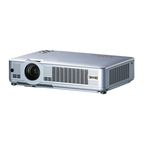
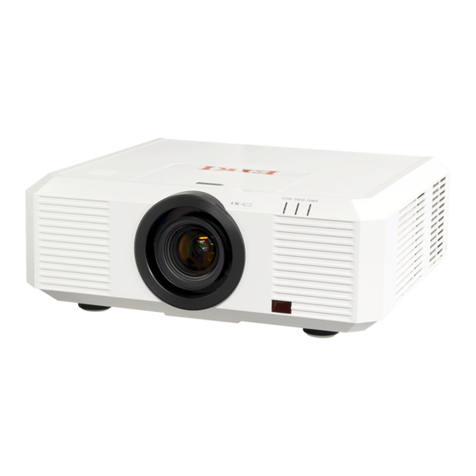
Eiki LC-WB42N User manual

Network Supported
□ WirelessLAN
IEEE802.11b/g/n
□ WiredLAN
100-Base-TX/10-Base-T
Memory Viewer
□ USBMemoryViewer
*Refertotheowner’smanualsbelowfordetails
aboutnetworkandmemoryviewerfunction.
■NetworkSet-upandOperation
■Memoryviewerfunction
Multimedia Projector
Owner's Manual
LC-WB42N
MODEL

2
Features and Design
ThisMultimediaProjectorisdesignedwiththemostadvancedtechnologyforportability,durability,andeaseofuse.
Thisprojectorutilizesbuilt-inmultimediafeatures,apaletteof16.77millioncolors,andmatrixliquidcrystaldisplay
(LCD)technology.
♦ Compact Design
Thisprojectorisdesignedcompactinsizeandweight.
Itiseasytocarryandinstalledanywhereyouwishto
use.
♦
Capable of 360-degree Projection
Thisprojectoriscapableof360-degreeprojection.
*Somerestrictionrequired,seepage7.
♦Simple Computer System Setting
TheprojectorhastheMulti-scansystemtoconformto
almostallcomputeroutputsignalsquickly(p.32).Upto
WUXGAresolutioncanbeaccepted.
♦
Power Management
ThePowermanagementfunctionreducespower
consumptionandmaintainsthelamplife(p.56).
♦Quick Termination
TheACpowercordcanbeunpluggedimmediately
after turning off the projector without waiting for the
terminationofthecoolingfanrotation(p.23).
♦ Logo Function
TheLogofunctionallowsyoutocustomizethescreen
logo(pp.50-52).Youcancaptureanimageforthe
screenlogoanduseitforthestarting-updisplayor
betweenpresentations.
♦ Multilanguage Menu Display
Operationmenuisavailablein17languages;English,
German,French,Italian,Spanish,Portuguese,Dutch,
Swedish,Finnish,Polish,Hungarian,Romanian,
Russian,Chinese,Korean,JapaneseandThai(p.47).
♦ Security Function
TheSecurityfunctionhelpsyoutoensuresecurityof
theprojector.WiththeKeylockfunction,youcanlock
theoperationonthetopcontrolortheremotecontrol
(p.59).PINcodelockfunctionpreventsunauthorized
useoftheprojector(pp.22,59-60).
♦
Helpful Maintenance Functions
Lampandfiltermaintenancefunctionsprovidefor
betterandpropermaintenanceoftheprojector.
♦LAN Network Function
ThisprojectorisloadedwiththeWiredandWireless
LANnetworkfunctions.
Note:
•TheOn-ScreenMenuandfiguresinthismanualmaydifferslightlyfromtheproduct.
•Thecontentsofthismanualaresubjecttochangewithoutnotice.
-Youcanprojectanimageonacomputeraswellas
operateandmanagetheprojectorvianetwork.
-Thisprojectorcorrespondsto"ConnecttoaNetwork
Projector"functionthatisthestandardequipmentfor
WindowsVista.
-Theprojectorhasthemoviefilestransmission
functionthatcanplaymoviefilestransmittedfroma
computertotheprojector.Thisfunctionenablesto
playbackmoviesverysmoothly.Thisprojectoralso
correspondstoIEEE802.11n(Draft2.0).
-ThisprojectoriscapableofthewirelessLANsimple
settingfunctionbyattachingthesuppliedUSB
memorytoacomputer.
Fordetails,refertotheowner’smanualof“Network
Set-upandOperation.”
♦Memory Viewer Function
InsertthededicatedUSBmemoryintotheprojector
toprojectimagesormoviefilesstoredwithin.Youdo
nothavetocarrycomputersorotherequipmentfora
presentation.
Fordetails,refertotheowner’smanualof"Memory
viewerfunction".
♦Auto setup Function
ThisfunctionenablesInputsearch,AutoKeystone
correctionandAutoPCadjustmentbysimplepressing
theAUTOSETUPbutton(pp.26,48).
♦Colorboard Function
Atthetimeofsimpleprojectiononthecoloredwall,
youcangettheclosecolorimagetothecolorimage
projectedonawhitescreenbyselectingthesimilar
colortothewallcolorfromthepresetfourcolors.
♦Closed Caption
ClosedCaptionisafunctionthatdisplaystheaudio
portionofaTVprogramastextonthescreen.Youcan
turnonthefeatureandswitchthechannels(p.57).
♦Picture in Picture Function
Thisprojectoriscapableofprojectingtwoimages
simultaneouslybyusingeitherbuilt-inPinPmodeorP
byPmode(p.55).

3
Table of Contents
Trademarks
Each name of corporations or products in this book is either a registered trademark or a trademark of its respective
corporation.
Features and Design . . . . . . . . . . . . . . . . . . .2
TableofContents......................3
TotheOwner..........................4
Safety Instructions . . . . . . . . . . . . . . . . . . . . .5
Air Circulation 6
Moving the Projector 6
Installing the Projector in Proper Position 7
Compliance...........................8
Part Names and Functions . . . . . . . . . . . . . .9
Front 9
Back 9
Bottom 9
Rear Terminal 10
Top Control 11
Remote Control 12
Remote Control Battery Installation 13
Remote Control Operating Range 13
Remote Control Code 13
Laser Pointer Function 14
Pointer Function 14
Wireless Mouse Operation 15
Adjustable Feet 15
Installation...........................16
Positioning the Projector 16
Connecting to a Computer 17
Connecting to Video Equipment 18
Connecting to Component Video Equipment 19
Connecting the AC Power Cord 20
BasicOperation......................21
Turning On the Projector 21
Turning Off the Projector 23
How to Operate the On-Screen Menu 24
Menu Bar 25
Zoom and Focus Adjustment 26
Auto Setup Function 26
Keystone Correction 26
Sound Adjustment 27
Remote Control Operation 28
ComputerInput ......................30
Input Source Selection
(Computer 1:RGB/Component/RGB(Scart)) 30
Input Source Selection
(Computer 2:RGB) 31
Computer System Selection 32
Auto PC adjustment 33
Manual PC adjustment 34
Image Mode Selection 36
Image Adjustment 37
Screen Size Adjustment 38
VideoInput ..........................40
Input Source Selection (Video, S-video) 40
Input Source Selection
(Component, RGB Scart 21-pin,HDMI) 41
Video System Selection 42
Image Mode Selection 43
Image Adjustment 44
Screen Size Adjustment 46
Setting..............................47
Setting 47
Information......................... 63
Input Source Information Display 63
Maintenance and Cleaning . . . . . . . . . . . . .64
WARNING indicator 64
Cleaning the Filters 65
Resetting the Filter Counter 65
Slide Shutter 66
Cleaning the Projection Lens 66
Cleaning the Projector Cabinet 66
Lamp Replacement 67
Resetting the Lamp Counter 68
Appendix............................69
Troubleshooting 69
Menu Tree 73
Indicators and Projector Condition 75
Compatible Computer Specifications 76
List of Picture in Picture 78
Technical Specifications 79
Optional Parts 80
PJ Link Notice 81
Configurations of Terminals 82
PIN Code Number Memo 83
USB Thumb Drive Case 83
Dimensions 84

4
To the Owner
CAUTION: TO REDUCE THE RISK OF ELECTRIC
SHOCK, DO NOT REMOVE COVER (OR
BACK). NO USER-SERVICEABLE PARTS
INSIDE EXCEPT LAMP REPLACEMENT.
REFER SERVICING TO QUALIFIED
SERVICE PERSONNEL.
THISSYMBOLINDICATESTHATDANGEROUS
VOLTAGECONSTITUTINGARISKOFELECTRIC
SHOCKISPRESENTWITHINTHISUNIT.
THISSYMBOLINDICATESTHATTHEREARE
IMPORTANTOPERATINGANDMAINTENANCE
INSTRUCTIONSINTHEOWNER'SMANUAL
WITHTHISUNIT.
CAUTION
RISK OF ELECTRIC SHOCK
DO NOT OPEN
Before installing and operating this projector, read this
manualthoroughly.
This projector provides many convenient features and
functions. Operating the projector properly enables
youto managethosefeatures andmaintainsit ingood
conditionformanyyearstocome.
Improperoperationmayresultinnotonlyshorteningthe
product-life, but also malfunctions, fire hazard, or other
accidents.
Ifyourprojectorseemstooperateimproperly,readthis
manualagain,checkoperationsandcableconnections
andtrythesolutionsinthe“Troubleshooting”sectionon
pages69-72ofthismanual.Iftheproblemstillpersists,
contactthedealerwhereyoupurchasedtheprojectoror
theservicecenter.
Safety Precaution
CAUTION
DO NOT SET THE PROJECTOR IN GREASY, WET, OR
SMOKY CONDITIONS SUCH AS IN A KITCHEN TO PREVENT
A BREAKDOWN OR A DISASTER. IF THE PROJECTOR
COMES IN CONTACT WITH OIL OR CHEMICALS, IT MAY
BECOME DETERIORATED.
READ AND KEEP THIS OWNER'S MANUAL FOR
LATER USE.
WARNING: ●THISAPPARATUSMUSTBEEARTHED.
●TOREDUCETHERISKOFFIREOR
ELECTRIC SHOCK, DO NOT EXPOSE THIS
APPLIANCE TO RAIN OR MOISTURE.
–Thisprojectorproducesintense lightfromtheprojection
lens. Do not stare directly into the lens, otherwise eye
damagecouldresult.Beespeciallycarefulthatchildren
donotstaredirectlyintothebeam.
–Installtheprojectorinaproperposition.Otherwiseitmay
resultinfirehazard.
–Allowing the proper amount of space on the top, sides,
and rear of the projector cabinet is critical for proper
air circulation and cooling of the unit. The dimension
shown here indicate the minimum space required.
If the projector is to be built into a compartment or
similarly enclosed, these minimum distances must be
maintained.
–Do not cover the ventilation slot on the projector. Heat
build-up can reduce the service life of your projector,
andcanalsobedangerous.
–Iftheprojectorisunusedforanextendedtime,unplug
theprojectorfromthepoweroutlet.
–Donotprojectthesameimageforalongtime.The
afterimagemayremainontheLCDpanelsbythe
characteristicofpanel.
SIDEandTOP REAR
CAUTION
NotforuseinacomputerroomasdefinedintheStandard
fortheProtectionofElectronicComputer/DataProcessing
Equipment,ANSI/NFPA75.
Nepeutêtreutilisédansunesalled’ordinateurstelle
que définie dans la norme ANSI/NFPA 75 Standard
forProtectionofElectronicComputer/DataProcessing
Equipment.
The symbol mark and recycling systems described below
applytoEUcountriesanddonotapplytocountriesinother
areasoftheworld.
Yourproductisdesignedandmanufacturedwithhighquality
materialsandcomponentswhichcanberecycledand/or
reused.
Thesymbolmarkmeansthatelectricalandelectronic
equipment, batteries and accumulators, at their end-oflife,
shouldbedisposed of separately fromyourhousehold
waste.
Note:
If a chemical symbol is printed beneath the symbol mark,
thischemicalsymbolmeansthatthebatteryoraccumulator
contains a heavy metal at a certain concentration. This will
beindicatedasfollows:Hg:mercury,Cd:cadmium,Pb:lead
IntheEuropeanUnionthereareseparatecollectionsystems
forusedelectricalandelectronicequipment,
batteriesandaccumulators.
Please,disposeofthemcorrectlyatyourlocal
communitywastecollection/recyclingcentre.
Please,helpustoconservetheenvironment
welivein!
0.7’(20cm)
1.5’(50cm) 3’(1m) 3’(1m)
20cm
50cm 1m 1m

5
Safety Instructions
All the safety and operating instructions should be read
beforetheproductisoperated.
Readalloftheinstructionsgivenhereandretainthem
forlateruse.UnplugthisprojectorfromACpowersupply
beforecleaning.Donotuseliquidoraerosolcleaners.
Useadampclothforcleaning.
Followallwarningsandinstructionsmarkedonthe
projector.
Foraddedprotectiontotheprojectorduringalightning
storm,orwhenitisleftunattendedandunusedforlong
periodsoftime,unplugitfromthewalloutlet.Thiswill
preventdamageduetolightningandpowerlinesurges.
Donotexposethisunittorainorusenearwater...for
example,inawetbasement,nearaswimmingpool,etc...
Donot useattachmentsnot recommended bythe
manufacturerastheymaycausehazards.
Donotplacethisprojectoronanunstablecart,stand,
ortable.Theprojectormayfall,causingseriousinjury
toachildoradult,andseriousdamagetotheprojector.
Useonlywithacartorstandrecommendedbythe
manufacturer,orsoldwiththeprojector.Wallorshelf
mountingshouldfollowthemanufacturer’sinstructions,
andshoulduseamountingkitapprovedbythe
manufacturers.
Anapplianceandcartcombination
shouldbemovedwithcare.Quick
stops,excessiveforce,anduneven
surfacesmaycausetheappliance
andcartcombinationtooverturn.
Slotsandopeningsinthebackandbottomofthecabinet
areprovidedforventilation,toensurereliableoperationof
theequipmentandtoprotectitfromoverheating.
Theopeningsshouldneverbecoveredwithclothorother
materials,andthebottomopeningshouldnotbeblocked
byplacing theprojectoron abed, sofa,rug, orother
similarsurface.Thisprojectorshouldneverbeplaced
nearoroveraradiatororheatregister.
Thisprojectorshouldnotbeplacedinabuilt-ininstallation
suchasabookcaseunlessproperventilationisprovided.
Neverpushobjectsofanykindintothisprojectorthrough
cabinetslotsastheymaytouchdangerousvoltagepoints
orshortoutpartsthatcouldresultinafireorelectric
shock.Neverspillliquidofanykindontheprojector.
Donotinstalltheprojectorneartheventilationductof
air-conditioningequipment.
Thisprojectorshouldbeoperatedonlyfromthetype
ofpowersourceindicatedonthemarkinglabel.Ifyou
arenotsureofthetypeofpowersupplied,consultyour
authorizeddealerorlocalpowercompany.
Donotoverloadwalloutletsandextensioncordsasthis
canresultinfireorelectricshock.Donotallowanything
torestonthepowercord.Donotlocatethisprojector
wherethecordmaybedamagedbypersonswalkingon
it.
Donotattempttoservicethisprojectoryourselfas
openingorremovingCoversmayexposeyouto
dangerousvoltageorotherhazards.Referallservicing
toqualifiedservicepersonnel.
Unplugthisprojectorfromwalloutletandreferservicing
toqualifiedservicepersonnelunderthefollowing
conditions:
a.Whenthepowercordorplugisdamagedorfrayed.
b.Ifliquidhasbeenspilledintotheprojector.
c.Iftheprojectorhasbeenexposedtorainorwater.
d.Iftheprojectordoesnotoperatenormallybyfollowing
theoperatinginstructions.Adjustonlythosecontrols
thatarecoveredbytheoperatinginstructionsas
improperadjustmentofothercontrolsmayresultin
damageandwilloftenrequireextensiveworkbya
qualifiedtechniciantorestoretheprojectortonormal
operation.
e.If theprojector hasbeen droppedorthecabinethas
beendamaged.
f.Whentheprojectorexhibitsadistinctchangein
performance-thisindicatesaneedforservice.
Whenreplacementpartsarerequired,besurethe
servicetechnicianhasusedreplacementpartsspecified
bythemanufacturerthathavethesamecharacteristics
astheoriginalpart.Unauthorizedsubstitutionsmay
resultinfire,electricshock,orinjurytopersons.
Uponcompletion ofanyservice orrepairs tothis
projector, ask the service technician to perform routine
safety checks to determine that the projector is in safe
operatingcondition.
NOTE FOR CUSTOMERS IN THE US
HgLAMP(S)INSIDETHISPRODUCTCONTAIN
MERCURYANDMUSTBERECYCLEDORDISPOSED
OFACCORDINGTOLOCAL,STATEORFEDERAL
LAWS.

6
Safety Instructions
Openingsinthe cabinetareprovided forventilation.To
ensurereliableoperationoftheproductandtoprotectit
from overheating, these openings must not be blocked
orcovered.
CAUTION
Hotairisexhaustedfromtheexhaustvent.Whenusing
or installing the projector, the following precautions
shouldbetaken.
–Donotputanyflammableobjectorspraycannearthe
projector,hotairisexhaustedfromtheairvents.
–Keeptheexhaustventatleast3’(1m)awayfromany
objects.
–Do not touch a peripheral part of the exhaust vent,
especiallyscrewsandmetallicparts.Theseareaswill
becomehotwhiletheprojectorisbeingused.
–Donotputanythingonthecabinet.Objectsputonthe
cabinetwillnotonlygetdamagedbutalsomaycause
firehazardbyheat.
Cooling fans are provided to cool down the projector.
The fans’ running speed is changed according to the
temperatureinsidetheprojector.
Air Circulation
ExhaustVent
(Hotairexhaust)
AirIntakeVent
CAUTION IN CARRYING OR TRANSPORTING
THE PROJECTOR
–Donotdroporbumptheprojector,otherwisedamages
ormalfunctionsmayresult.
–Whencarryingtheprojector,useasuitablecarrying
case.
–Donottransporttheprojectorbycourieroranyother
transportserviceinanunsuitabletransportcase.This
maycausedamagetotheprojector.Forinformation
abouttransportingtheprojectorbycourieroranyother
transportservice,consultyourdealer.
–Donotputtheprojectorinacasebeforetheprojector
iscooledenough.
Moving the Projector
Whenmovingtheprojector,closetheSlideShutterand
retractadjustablefeettopreventdamagetothelens
andcabinet.
Whentheprojectorisnotinuseforanextendedperiod,
putitintothesuppliedcarryingcasewiththelensside
up.
CAUTION
Thecarryingcase(supplied)isintendedforprotection
againstdustandscratchesonsurfaceofthecabinet,
anditisnotdesignedtoprotectanappliancefrom
externalforces.Donottransporttheprojectorbycourier
oranyothertransportservicewiththiscase,otherwise
theprojectorcanbedamaged.Whenhandlingthe
projector,donotdrop,bump,subjectittostrongforces,
orputotherthingsonthecabinet.
AirIntakeVent
AirIntakeVent

7
Safety Instructions
Usetheprojectorproperlyinspecifiedpositions.Improperpositioningmayreducethelamplifeandresultinsevere
accidentorfirehazard.
Thisprojectorcanprojectthepictureupward,downwardorbackward,perpendiculartotheplaneofthescreenas
showninthefigurebelow.
Bottom
Downward
(Usual)
Front
Downward
Bottom
Upward
Front
Upward
Installing the Projector in Proper Directions
Avoidpositioningtheprojectorasdescribedbelowwheninstalling.
Positioning Precautions
Donotrolltheprojectormorethan10degreesfromsidetoside.
Donotputtheprojectoroneithersidetoprojectanimage.
10˚
10˚
10˚ 10
˚
10˚10
˚
Inupwardprojection,donottilttheprojectorover10degreesrightandleft.
Indownwardprojection,donottilttheprojectorover10degreesrightandleft.
0º
90º
180 º
40º
50º
140º
50º
40º
BesuretosettheLampcontrolinHighandtheFancontrolinOn3inthe
settingmenuwhenusingtheprojectorinclinedatbetween+40degrees
to+140degreestothehorizontalplaneataltitudesbetween0and
approximately1,600metersabovesealevel.
BesuretosettheFancontrolinOn2whenusingtheprojectorathigher
altitudesthanthealtitudesdescribedabove,regardlessoftheinstallation
positionoftheprojector.(p.61).

8
Compliance
Federal Communications Commission Notice
Note:ThisequipmenthasbeentestedandfoundtocomplywiththelimitsforaClassBdigitaldevice,pursuant
to Part 15 of the FCC Rules.These limits are designed to provide reasonable protection against harmful
interference in a residential installation.This equipment generates, uses, and can radiate radio frequency
energy, and if not installed and used in accordance with the instructions, may cause harmful interference
toradiocommunications.However,thereisnoguaranteethatinterferencewillnotoccurinaparticular
installation. If this equipment does cause harmful interference to radio or television reception, which can be
determinedbyturningtheequipmentoffandon,theuserisencouraged totrytocorrecttheinterferenceby
oneormoreofthefollowingmeasures:
–Reorientorrelocatethereceivingantenna.
–Increasetheseparationbetweentheequipmentandreceiver.
–Connecttheequipmentintoanoutletonacircuitdifferentfromthattowhichthereceiverisconnected.
–Consultthedealeroranexperiencedradio/TVtechnicianforhelp.
UseofshieldedcableisrequiredtocomplywithclassBlimitsinSubpartBofPart15ofFCCRules.
Donotmakeanychangesormodificationstotheequipmentunlessotherwisespecifiedintheinstructions.If
suchchangesormodificationsshouldbemade,youcouldberequiredtostopoperationoftheequipment.
ModelNumber:LC-WB42N
TradeName:EIKI
Responsibleparty:EIKIInternational,Inc.
Address :30251EsperanzaRanchoSantaMargaritaCA92688-2132
TelephoneNo.:800-242-3454(949-457-0200)
TheACPowerCordsuppliedwiththisprojectormeetstherequirementforuseinthecountryyoupurchasedit.
AC Power Cord for the United States and Canada:
ACPowerCord usedin theUnitedStates andCanadais listedby theUnderwriters
Laboratories(UL)andcertifiedbytheCanadianStandardAssociation(CSA).
ACPowerCordhasagrounding-typeAClineplug.Thisisasafetyfeaturetobesurethatthe
plugwillfitintothepoweroutlet.Donottrytodefeatthissafetyfeature.Shouldyoubeunable
toinserttheplugintotheoutlet,contactyourelectrician.
GROUND
AC Power Cord Requirement
AC Power Cord for the United Kingdom:
Thiscordisalreadyfittedwithamouldedplugincorporatingafuse,thevalueofwhichisindicatedonthepin
faceoftheplug.Shouldthefuseneedtobereplaced,anASTAapprovedBS1362fusemustbeusedofthe
samerating,markedthus
ASA
.Ifthefusecoverisdetachable,neverusetheplugwiththecoveromitted.Ifa
replacementfusecoverisrequired,ensureitisofthesamecolourasthatvisibleonthepinfaceoftheplug
(i.e.redororange).FusecoversareavailablefromthePartsDepartmentindicatedinyourUserInstructions.
Iftheplugsuppliedisnotsuitableforyoursocketoutlet,itshouldbecutoffanddestroyed.
Theendoftheflexiblecordshouldbesuitablypreparedandthecorrectplugfitted.
WARNING : A PLUG WITH BARED FLEXIBLE CORD IS HAZARDOUS IF ENGAGED IN A LIVE SOCKET
OUTLET.
TheWiresinthismainsleadarecolouredinaccordancewiththefollowingcode:
Green-and-yellowEarth
Blue . . . . . . . . . . . Neutral
Brown . . . . . . . . . Live
Asthecoloursofthewiresinthemainsleadofthisapparatusmaynotcorrespondwiththecolouredmarkings
identifyingtheterminalsinyourplugproceedasfollows:
Thewirewhichiscolouredgreen-and-yellowmustbeconnectedtotheterminalintheplugwhichismarkedby
theletterEorbythesafetyearthsymbol orcolouredgreenorgreen-and-yellow.
ThewirewhichiscolouredbluemustbeconnectedtotheterminalwhichismarkedwiththeletterNor
colouredblack.
ThewirewhichiscolouredbrownmustbeconnectedtotheterminalwhichismarkedwiththeletterLor
colouredred.
WARNING: THIS APPARATUS MUST BE EARTHED.
THE SOCKET-OUTLET SHOULD BE INSTALLED NEAR THE EQUIPMENT AND EASILY ACCESSIBLE.

9
Part Names and Functions
Bottom
Back
⑯
⑮⑭⑬⑪
⑫
⑰
⑨
⑩
⑪
⑱
Kensington Security Slot
ThisslotisforaKensingtonlockusedtodetertheft
oftheprojector.
* KensingtonisaregisteredtrademarkofACCOBrands
Corporation.
①Infrared Remote Receiver
②WIRELESS Indicator
③ Focus Ring
④ Projection Lens
⑤Zoom Lever
⑥ Slide Shutter
⑦Top Controls and Indicators
⑧Air Intake Vent
⑨Exhaust vent
⑩Speaker
⑪Air Intake Vent (back and bottom)
⑫Terminals and Connectors
⑬Power Cord Connector
⑭USB Connector (Series A)
⑮LAN Connection Terminal
⑯Lamp Cover
⑰Filters
⑱Adjustable Feet
CAUTION
Hotairisexhaustedfromtheexhaustvents.
Donotputheat-sensitiveobjectsnearthis
side.
Note:
② WIRELESSIndicatorand⑮ LAN
ConnectionTerminalarefortheNetwork
function.Refertotheowner’smanualof
“NetworkSet-upandOperation”.
⑭USBConnector(SeriesA)isforthe
MemoryViewerfunction.Refertothe
owner'smanualof"MemoryViewer
function".
CAUTION
Donotturnonaprojectorwithslideshutter
closed.Hightemperaturefromlight
beammaydamageslideshutterandresult
infirehazard.
Front
⑥③ ④ ⑤① ⑦ ⑧②⑧

10
Part Names and Functions
Rear Terminal
⑨S-VIDEO IN
ConnecttheS-VIDEOoutputsignalfromvideo
equipmenttothisjack(p.18).
⑫AUDIO IN
Connecttheaudiooutputsignalfromvideo
equipmentconnectedto⑨or⑬tothisjack.
Foramonoaudiosignal(asingleaudiojack),
connectittotheL(MONO)jack(p.18).
⑪ COMPUTER 1 COMPONENT / COMPUTER 2
AUDIO IN
Connecttheaudiooutput(stereo)froma
computerorvideoequipmentconnectedto④,
⑤or⑥ tothisjack.(pp17,19)
⑬VIDEO IN
Connectthecompositevideooutputsignalto
thisjack(p.18).
④COMPUTER IN 1 / COMPONENT IN
Connectoutputsignalfromacomputer,RGBscart
21-pinvideooutputorcomponentvideooutputto
thisterminal(pp.17,19).
⑩AUDIO OUT (VARIABLE)
Connectanexternalaudioamplifiertothisjack
(pp.17-19).
ThisterminaloutputssoundfromAUDIOINterminal
(⑪or⑫).
⑦LAN Connection Terminal
ConnecttheLANcable(refertotheowner’smanual
of“NetworkSet-upandOperation”).
②USB Connector (Series B)
Inordertooperatethecomputerwiththeremote
controlandusethePAGE▲▼buttonsonthe
remotecontrolduringapresentation,connectthe
USBportofthecomputertotheUSBterminalwitha
USBcable(notsupplied)(p.17).
⑧USB Connector (Series A)
ConnecttheUSBmenory(refertotheowner’s
manual“NetworkSet-upandOperation”).
② ③① ④ ⑦
⑧⑫ ⑨⑪
③CONTROL PORT
WhencontrollingtheprojectorwithRS-232C,
connectthecontrolequipmenttothisconnectorwith
theserialcontrolcable.
⑩⑬
⑤ ⑥
①R/C JACK
Whenusingthewiredremotecontrol,connect
thewiredremotecontroltothisjackwitharemote
controlcable(supplied).
⑥HDMI
ConnecttheHDMIsignal(includingsoundsignal)
fromvideoequipmentortheDVIsignalfrom
computertothisterminal(pp.17,19).
⑤COMPUTER IN 2 / MONITOR OUT
–Connectcomputeroutputtothisterminal(p.17).
–Thisterminalcanbeusedtooutputtheincoming
analogRGBsignalandcomponentsignalsfrom
COMPUTERIN1/COMPONENTINterminaltothe
othermonitor(p.17).
* isregisteredtrademarksofHDMI
Licensing,LLC.
*

11
Part Names and Functions
Top Control
⑩LAMP REPLACE indicator
Lightsyellowwhentheprojectionlampreachesits
endoflife(pp.67,75).
⑥ WARNING indicator
–Lightsredwhentheprojectordetectsanabnormal
condition.
–Blinksredwhentheinternaltemperatureofthe
projectorexceedstheoperatingrange(pp.64,75).
⑨ON/STAND–BY button
Turntheprojectoronoroff(pp.21-23).
⑤POWER indicator
–Lightsredwhentheprojectorisinstand-bymode.
–Lightsgreenduringoperations.
–BlinksgreeninthePowermanagementmode
(p.56).
⑧INPUT button
Selectaninputsource(pp.30-31,40-41).
③ MENU button
OpenorclosetheOn-ScreenMenu(p.24).
②POINT ▲▼◄► (VOLUME +/–) buttons
–SelectanitemoradjustthevalueintheOn-Screen
Menu(p.24).
–PantheimageintheDigitalzoom+mode(p.39).
–Adjustthevolumelevel(Point◄►buttons)(p.27).
④ AUTO SETUP/CANCEL button
–Correctverticalkeystonedistortionandadjust
computerdisplayparameterssuchasFine sync,
Total dots,Horizontal andVerticalposition
(pp.26,48).
–DisplaytheimageinUSBthumbdriveorreturnto
themenubarinMemoryViewermenu.
Refertotheowner'smanualof"Memory
Viewerfunction".
①SELECT button
–Executetheselecteditem(p.24).
–ExpandorcompresstheimageintheDigitalzoom
mode(p.39).
①
②
③
④
⑤
⑥
⑦
⑧
⑨
⑩
⑦KEYSTONE button
Correctkeystonedistortion(pp.26,49).

12
Part Names and Functions
㉘NETWORK button
SelecttheNetworkinput.Seetheowner'smanualof“NetworkSet-upand
Operation”andowner'smanualof"Memoryviewerfunction".
Note:
Toensuresafeoperation,pleaseobservethe
followingprecautions:
– Donotbend,drop,orexposetheremotecontrolto
moistureorheat.
– Forcleaning,useasoftdrycloth.Donotapply
benzene,thinner,spray,oranychemicalmaterial.
Remote Control
①
⑧
⑮
⑪
⑤ ②
⑨
⑩
⑭
⑰
⑥
⑦
⑫
⑬
⑯
④
②ON/STAND-BY button
Turntheprojectoronoroff.(pp.21-23)
⑥HDMI button
SelecttheHDMIinputsource.(pp.28,41)
⑦COMPUTER button
SelecttheCOMPUTERinputsource.(pp.30-31,41)
⑭PAGE ▲▼buttons
Scrollbackandforththepagesonthescreenwhengivingapresentation.Touse
thesebuttons,connecttheprojectorandyourcomputerwithaUSBcable.(pp.10,
17)
⑧INFO. button
Operatetheinformationfunction.(p.63)
⑯D.ZOOM +/-buttons
Zoominandouttheimages.(pp.28,39)
⑪MENU button
OpenorclosetheOn-ScreenMenu.(p.24)
⑰RESET/ON/ALL-OFF switch
Whenusingtheremotecontrol,setthisswitchto“ON.”Setitto“ALLOFF”for
powersavingwhenitisnotused.Slidethisswitchto“RESET”toinitializethe
remotecontrolcodeorswitchSpotlightandPointertotheLaserpointerfunction.
(pp.13-14)
⑳IMAGE button
Selecttheimagemode.(pp.29,36,43)
㉑MUTE button
Mutethesound.(p.27)
⑨
KEYSTONE button
Correctkeystonedistortion.(pp.26,49)
⑩Point ▲▼◄►(VOLUME
+/–)
buttons
–SelectanitemoradjustthevalueintheOn-ScreenMenu.(p.24)
–PantheimageintheDigitalzoom+mode.(p.39)
–Adjustthevolumelevel.(Point◄►buttons)(p.27)
㉓NO SHOW button
Temporarilyturnofftheimageonthescreen.(p.29)
⑬ LASER button
–OperatetheLaserpointerfunction.Laserbeamisemittedwhilepressingthis
buttonwithin1minute.Whenusingthislaserpointerformorethan1minute,
releasetheLASERbuttonandpressitagain.(p.14)
–DisplaythePointeronthescreen.(p.14)
①L-CLICK button
Actastheleftmousebuttonforwirelessmouse
operation.(p.15)
④SIGNAL EMISSION indicator
Lightsredwhilethelaserbeamisbeingemitted
fromthelaserlightwindoworasignalisbeingsent
fromtheremotecontroltotheprojector.
⑫FREEZE button
Freezethepictureonthescreen.(p.28)
⑮LAMP button
Selectalampmode.(pp.28,58)
㉒P-TIMER button
OperatetheP-timerfunction.(p.29)
㉔R-CLICK button
Actastherightmousebuttonforwirelessmouseoperation.(p.15)
㉕SELECT button
–Executetheselecteditem.(p.24)
– ExpandorcompresstheimageinDigitalzoommode.(p.39)
㉖PRESENTATION POINTER button
Moveapointeroftheprojectororapointerforwirelessmouseoperation.(pp.14-15)
㉗AUTO SET/CANCEL button
–Correctverticalkeystonedistortionandadjustcomputerdisplayparameterssuch
asFine sync,Total dots,Horizontal andVerticalposition.(pp.26,48)
–DisplaytheimageinUSBthumbdriveorreturntothemenubarinMemory
Viewermenu.
Refertotheowner'smanualof"Memoryviewerfunction".
⑤LASER LIGHT window
Alaserbeamisemittedfromhere(p.14).
⑲SCREEN button
Selectascreenmode.(pp.29,38-39,46)
㉙VIDEO button
SelecttheVIDEOinputsource.(pp.28,40)
⑱PIP button
OperatethePictureInPicturefunction.(pp.28,55)
㉑
㉒
㉔
⑳
㉓
㉕
㉖
㉗
㉘
⑱
⑲
㉙
③
③WIRED REMOTE jack
Connecttheremotecontrolcable(supplied)tothis
jackwhenusingasawiredremotecontrol.Wireless
remotecontroldoesnotworkwhentheremote
controlcableisconnectedtotheprojector.

13
Part Names and Functions
Toensuresafeoperation,pleaseobservethefollowingprecautions:
● Usetwo(2)AAAorLR03typealkalinebatteries.
● Alwaysreplacebatteriesinsets.
● Donotuseanewbatterywithausedbattery.
● Avoidcontactwithwaterorliquid.
● Donotexposetheremotecontroltomoistureorheat.
● Donotdroptheremotecontrol.
● Ifthebatteryhasleakedontheremotecontrol,carefullywipethecasecleanandinstallnewbatteries.
● Riskofanexplosionifbatteryisreplacedbyanincorrecttype.
● Disposeofusedbatteriesaccordingtotheinstructionsoryourlocaldisposalruleorguidelines.
Pressthelid
downwardandslideit.
Openthebattery
compartmentlid.
Installnewbatteries
intothecompartment.
Replacethe
compartmentlid.
Two AAA size batteries
Forcorrectpolarity
(+and–),besure
batteryterminalsare
incontactwithpinsin
compartment.
1 2 3
Pointtheremotecontroltowardtheprojectorwhenpressing
thebuttons.Maximumoperatingrangefortheremote
controlisabout16.4'(5m)and60degreesinfrontofthe
projector.
Remote Control Operating Range
Remote Control Battery Installation
16.4'
(5m)
30°
Remotecontrol
30°
WhilepressingtheMENU
button,presstheIMAGE
buttonnumberoftimes
correspondingtotheremote
controlcode.
MENU button
IMAGE button
RESET/ON/ALL-
OFF switch
Remote Control Code
Remote Control Code Number of Times
Pressing IMAGE
Button
Code 1 1
Code 2 2
Code 3 3
Code 4 4
Code 5 5
Code 6 6
Code 7 7
Code 8 8
Theeightdifferentremotecontrolcodes(Code1–Code8)areassignedtothisprojector.Switchingtheremote
controlcodespreventsinterferencefromotherremotecontrolswhenseveralprojectorsorvideoequipment
nexttoeachotherareoperatedatthesametime.Changetheremotecontrolcodefortheprojectorfirstbefore
changingthatfortheremotecontrol.See"Remotecontrol"intheSettingMenuonpage58.
WhilepressingtheMENUbutton,presstheIMAGE
buttonnumberoftimescorrespondingtotheremote
controlcode.Seethelistbelow.
1
Toinitializetheremotecontrolcode,slidetheRESET/
ON/ALL-OFFswitchtoRESET,andthentoON.The
initialcodeissettoCode 1.
2

14
Part Names and Functions
Spotlight
Pointer Function
Pointer
Laser Pointer Function
LASERbutton
PRESENTATIONPOINTER
button
Thisremotecontrolemitsalaserbeamfromthelaserlightwindow.PresstheLASERbuttontoactivatethe
laserpointer.Thesignalemissionindicatorlightsredandtheredlaserbeamisemitted.IftheLASERbuttonis
pressedformorethanoneminuteorifitisreleased,thelaserlightgoesoff.
ThelaseremittedisaClassIIlaser.Donotlookintothelaserlightwindoworpointthelaserbeamatyourselfor
otherpeople.Thefollowingisthecautionlabelforthelaserbeam.
CAUTION: Useofcontrols,adjustmentsorperformanceofproceduresotherthanthosespecifiedhereinmay
resultinhazardousradiationexposure.Neverlookdirectlyintothelaserlightwindowwhilealaser
isemitted,otherwiseeyedamagemayresult.
Thecautionlabelisputontheremotecontrol.
YoucanmovetheSpotlightorPointeroftheprojectorwiththeremotecontroltoemphasizeapartofthe
projectedimage.
PressandholdtheMENUandtheNOSHOWbuttons
formorethan5secondstoactivatethePointerfunction.
(TheLaserpointerhasswitchedtothePointerfunction.)
1
PresstheLASERbuttonontheremotecontrolpointing
towardtheprojector.TheSpotlightorPointeris
displayedonthescreenwiththeLASERbuttonlighting
green.ThenmovetheSpotlightorPointerwiththe
PRESENTATIONPOINTERbutton.IftheLASERbutton
doesnotlightgreenandcontinuestoemitalaserbeam,
trytheabovementionedprocedureuntiltheLASER
buttonlightsgreen.
2
TocleartheSpotlightorPointeroutthescreen,press
theLASERbuttonpointingtowardtheprojectorandsee
iftheLASERbuttonlightingisturnedoff.
ToswitchtotheLaserpointeragain,pressandholdthe
NOSHOWandMENUbuttonsformorethan5seconds
orslidetheRESET/ON/ALL-OFFswitchtoRESETand
thentoON.
WhenyouresetthePointerfunction,theremotecontrol
codewillbereset,aswell.
3
Note:
YoucanchoosethesizeofSpotlight(Large/Middle/
Small)andthepatternofPointer(Arrow/Finger/Dot)in
theSettingMenu.See“Pointer”onpage54.
AftertheLaserpointerhas
switchedtothePointer,use
theLASERbuttonasthe
PointerfunctionON-OFF
switch.PresstheLASER
buttonpointingtowardthe
projectorandseeifitlights
green.
LaserLightWindow
SignalEmissionIndicator
MENUbutton
NOSHOWbutton
PressandholdtheMENU
andNOSHOWbuttonsfor
morethan5seconds.
PRESENTATIONPOINTER
button

15
Part Names and Functions
Adjustable Feet
Projectionanglecanbeadjustedupto8.9degreeswiththe
adjustablefeet.
Liftthefrontoftheprojectorandpullthefeetlocklatcheson
bothsideoftheprojector.
Releasethefeetlocklatchestolocktheadjustablefeetand
rotatetheadjustablefeettoaproperheightandtilt.
Keystone distortion can be adjusted automatically with the
Autosetupfunctionormanuallybyusingtheremotecontrol
orthemenuoperation(seepages26,48-49).
PRESENTATION POINTER
button
R-CLICK button
L-CLICK button
Wireless Mouse Operation
Theremotecontrolcanbeusedasawirelessmouseforyourcomputer.
Actasleft(click)mouse
buttonwhiletheprojector
andacomputerare
connectedwithaUSB
cable.
Movethepointeronthescreen
withthisbutton.
Actasright(click)mouse
buttonwhiletheprojectoranda
computerareconnectedwitha
USBcable.
Beforeoperatingthewirelessmouse,connect
yourcomputerandtheprojectorwithaUSB
cable(notsupplied).See“Connectingtoa
Computer”onpage17.WhenthePointer
functionisused,thewirelessmouseisnot
available.
1
WhenaUSBcableisconnectedtothe
computerandtheprojector,turnonthe
projectorfirst,thenthecomputer.Ifyouturn
onthecomputerfirst,thewirelessmouse
functionmaynotoperatecorrectly.
2
PAGE ▲▼buttons
Scrollbackandforththepages
onthescreenwhengivinga
presentation.
AdjustableFeet
FeetLockLatches

16
Positioning the Projector
Forprojectorpositioning,seethefiguresbelow.Theprojectorshouldbesetperpendicularlytotheplaneofthe
screen.
Installation
Note:
•Thebrightnessintheroomhasagreatinfluenceonpicturequality.Itisrecommendedtolimitambient
lightinginordertoobtainthebestimage.
•Allmeasurementsareapproximateandmayvaryfromtheactualsizes.
A
B
100"
150"
200" 189
127
95
63
300"(wide)
40"
300"(tele )
39.7'(12.1m)
25.2'(7.7m)
16.7'(5.1m)
12.5'(3.8m)
Max. Zoom Min. Zoom
A : B = 49 : 1
(Inch Diagonal)
8.2'(2.5m)
(Center)
3.3'(1.0m)
Screen Size
(W x H) mm
16 : 10 aspect ratio
40”
Zoom (max)
862 x 538
3.3'(1.0m)
100”
2154 x 1346
8.2'(2.5m)
150”
3231 x 2019
12.5'(3.8m)
200”
4308 x 2692
16.7'(5.1m)
300”
6462 x 4039
25.2'(7.7m)
Zoom (min) 5.2'(1.6m) 13.1'(4.0m) 19.7'(6.0m) 26.86(8.1m) 39.7'(12.1m)

17
Installation Installation
Connecting to a Computer
Cables used for connection
•VGAcables(MiniD-sub15pin)*
•USBcable
•Audiocables
•HDMI-DVIcable
(*Onecableissupplied;othercablesarenotsuppliedwiththeprojector.)
Note:
•InputsoundtotheCOMPUTER1COMPONENT/COMPUTER
2AUDIOINterminalwhenusingtheCOMPUTERIN1/
COMPONENTINandtheCOMPUTERIN2/MONITOROUT
terminalasinput.
•WhentheAUDIOOUTisplugged-in,theprojector'sbuilt-in
speakerisnotavailable.
•USBcableconnectionisneededwhenoperatingthecomputer
withtheremotecontrolorusingthePAGE▲▼buttonsonthe
remotecontrol.
• Whenthecableisofthelongervariety,itisadvisableto
usetheCOMPUTERIN1/COMPONENTINandnotthe
COMPUTERIN2.
Unplugthepowercordsofboththe
projectorandexternalequipment
fromtheACoutletbeforeconnecting
cables.
ExternalAudioEquipment
Audiocable
(stereo)
Audiocable
(stereo)
AudioOutput
COMPUTER1COMPONENT/
COMPUTER2AUDIOIN
AUDIOOUT
(stereo)
AudioInput
Monitor
Output
COMPUTERIN2/
MONITOROUT
USBcable VGA
cable
COMPUTERIN1
COMPONENT
VGA
cable
MonitorOutput/
MonitorInput
HDMI-DVI
cable
DVI
Output
HDMI
USB
Thisterminalis
switchable.Setup
theterminalas
COMPUTERIN2or
MONITOROUT.(See
Page53.)
Note:
•AnalogRGBandcomponentsignalscannotbe
outputfromtheCOMPUTERIN2/MONITOR
OUTterminalwhenusingtheCOMPUTERIN
2/MONITOROUTterminalasoutput.
•WhenDVIsignalisconnectedtoHDMIterminal
withHDMI-DVIcable,connectthesoundsignal
toCOMPUTER2AUDIOINandsetupSoundof
"HDMIsetup"to"Computer2".(p.53)

18
Installation
Connecting to Video Equipment
Cables used for connection
•VideoandAudiocable(RCAx3)
•S-videocable
•Audiocable
(Cablesarenotsuppliedwiththeprojector.)
Unplugthepowercordsof
boththeprojectorandexternal
equipmentfromtheACoutlet
beforeconnectingcables.
Note:
WhentheAUDIOOUTisplugged-in,theprojector'sbuilt-
inspeakerisnotavailable.
ONON
ExternalAudioEquipment
Audiocable
(stereo)
VIDEO S-video
S-videocable
VideoandAudiocable
VideoandAudioOutput
S-videoOutput
AUDIOIN
AudioInput
AUDIOOUT(stereo)
(R)(L)(Video)

19
Installation
Connecting to Component Video Equipment
Note:
•WhentheAUDIOOUTisplugged-in,theprojector's
built-inspeakerisnotavailable.
•Seepage80fororderingoptionalcables.
Unplugthepowercordsof
boththeprojectorandexternal
equipmentfromtheACoutlet
beforeconnectingcables.
ExternalAudioEquipment
COMPUTER1
COMPONENT/
AUDIOIN
Audiocable
(stereo)
Audio
cable
(stereo)
AudioInput
ComponentVideoOutput
(Y,Pb/Cb,Pr/Cr)
RGBScart21-
pinOutput
Audio
Output
Scart-VGA
cable
Component-
VGAcable
AUDIOOUT(stereo)
Component
cable
COMPUTERIN1/COMPONENTIN
Cables used for connection
•Audiocables
•Scart-VGAcable
•Componentcable
•HDMIcable
•Component-VGAcable
(Cablesarenotsuppliedwiththisprojector.)
HDMI
HDMIOutput
HDMI
cable

20
Installation
Connecting the AC Power Cord
Thisprojectorusesnominalinputvoltagesof100-120Vor
200–240VACanditautomaticallyselectsthecorrectinput
voltage.Itisdesignedtoworkwithsingle-phasepower
systemshavingagroundedneutralconductor.Toreduce
theriskofelectricalshock,donotplugintoanyothertypeof
powersystem.
Ifyouarenotsureofthetypeofpowerbeingsupplied,
consultyourauthorizeddealerorservicestation.
Connecttheprojectorwithallperipheralequipmentbefore
turningtheprojectoron.
Note:
UnplugtheACpowercordwhentheprojectorisnot
inuse.Whenthisprojectorisconnectedtoanoutlet
withtheACpowercord,itisinStand-bymodeand
consumesalittleelectricpower.
ConnecttheACpowercord(supplied)tothe
projector.
TotheACoutlet.
(200 - 240 V AC)
NOTE ON THE POWER CORD
ACpowercordmustmeetrequirementofthecountrywhereyouusetheprojector.
ConfirmtheACplugtypewiththechartbelowandproperACpowercordmustbeused.
IfsuppliedACpowercorddoesnotmatchyourACoutlet,contactyoursalesdealer.
Topowercord
connectoronyour
projector.
Projector side AC outlet side
Ground
TotheACoutlet.
(120 V AC)
For the U.S.A. and Canada
TotheACoutlet.
(200 - 240 V AC)
For the U.K.For Continental Europe
CAUTION
TheACoutletmustbenearthisequipmentandmustbe
easilyaccessible.
Other manuals for LC-WB42N
1
Table of contents
Other Eiki Projector manuals

Eiki
Eiki LC-XB43 User manual

Eiki
Eiki LC-X990 Setup guide

Eiki
Eiki LC-HDT700 User manual

Eiki
Eiki LC-330 Setup guide

Eiki
Eiki LC-SVGA860 Setup guide

Eiki
Eiki 3990BDA User manual

Eiki
Eiki EK-301W User manual

Eiki
Eiki LC-WIP3000 User manual

Eiki
Eiki LC UXT1 LC-UXT1 LC-UXT1 Setup guide

Eiki
Eiki LC-4200 User manual