EIPL HM150-H User manual
Page 1 of 12
Drawing : - TPC601
Issue : - 1
Date : - 08/06/23
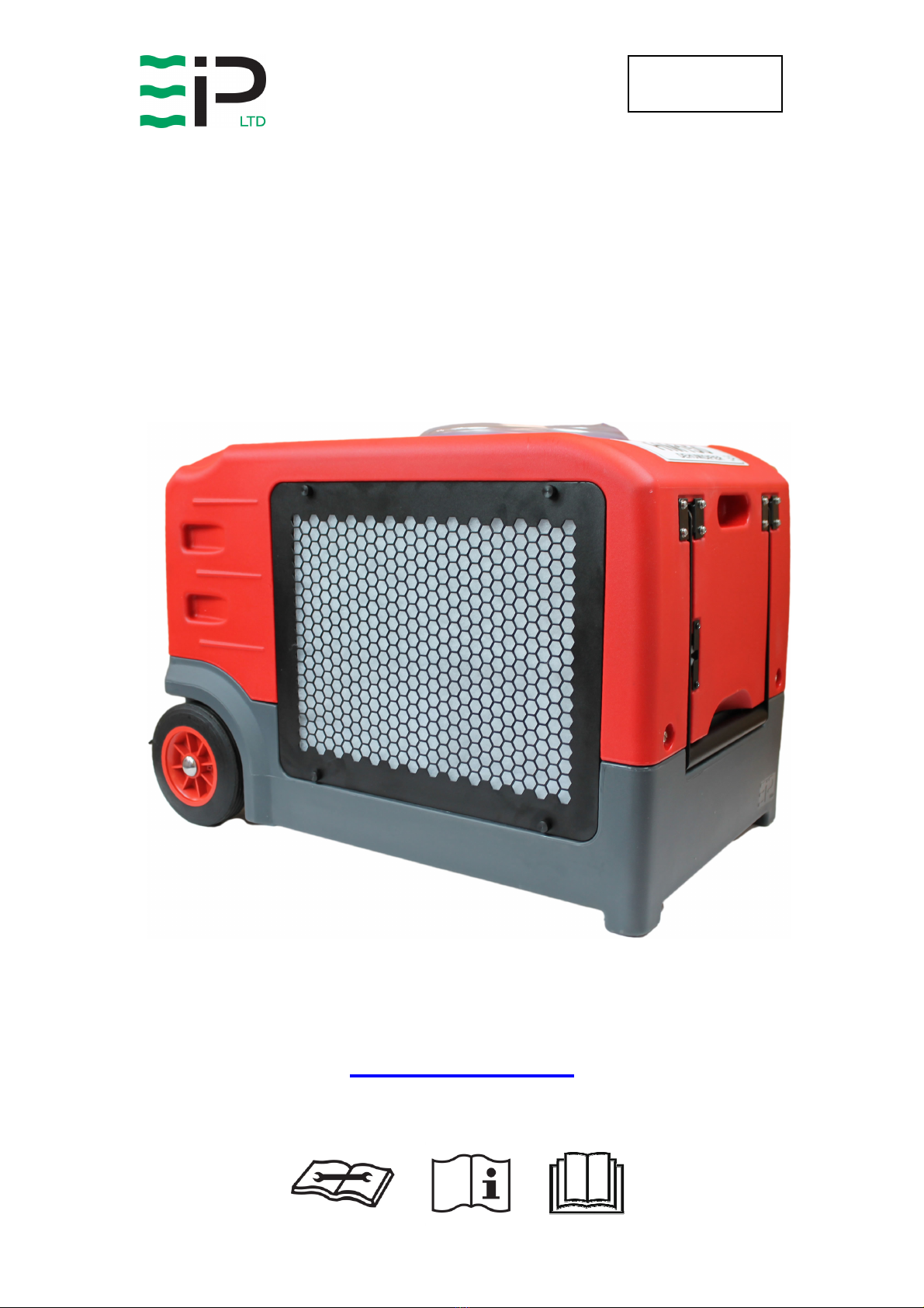
HM150
HM150HM150
HM150-
--
-H
HH
H
DEHUMIDIFIER
DEHUMIDIFIERDEHUMIDIFIER
DEHUMIDIFIER
OWNER’S MANUAL
www.eipl.co.uk

Page 2 of 12
Drawing : - TPC601
Issue : - 1
Date : - 08/06/23
SAFETY INFORMATION
Children shall not play with the appliance.
This appliance can be used by children from 8 years and above and persons with reduced
physical, sensory or mental capabilities or lack of experience and knowledge if they have
been given supervision or instruction concerning use of the application in a safe way and
understand the hazards involved.
Cleaning and user maintenance shall not be made by children without supervision.
If the SUPPLY CORD is damaged, it must be replaced by the manufacturer, its service agent
or similarly qualified person in order to avoid hazard.
If the appliance is switched off at the mains power supply for any reason, the unit must be
allowed to stand at rest for at least three minutes before restarting.
Due to the high pressures within the refrigeration circuit, under no circumstances must direct
heat be applied to the evaporator coil in an attempt to remove the build-up of ice.
No attempt should be made to cut open any part of the refrigeration circuit due to high
pressures and gas involved.
If the appliance is switched off at the mains power supply for any reason, it must be allowed
to stand at rest for at least three minutes before restarting. Failure to do so may cause the
appliance to blow the fuses owing to the compressor due to there being a refrigerant
imbalance.
The Global Warming Potential (GWP) of refrigerants used in products manufactured by Ebac
Industrial Products Ltd is as follows: -
R290 – 3
R454c – 148
For type and weight of refrigerant contained in this appliance, please refer to the product data
label
Do not insert objects into any of the grilles on the machine.
Do no cover or obstruct airflow from the grilles.
Do not operate the unit with the covers removed
Do not stand on the unit
Do not attempt to lift heavy units unassisted.
Do check the plug on the unit matches the supply.
Do check the supply cord and power supply are earthed correctly
Do check the voltage selection before attempting to power up the unit (This is for dual voltage
units only).
Do use a residual current device “RCD” where possible

Page 3 of 12
Drawing : - TPC601
Issue : - 1
Date : - 08/06/23
The appliance uses R454c refrigerant gas. This gas is much
kinder to the environment as it is non-toxic with zero Ozone
Depletion Potential (ODP). This is a flammable gas and the
following warnings should be considered:
•The appliance uses a flammable refrigerant (see unit serial plate for
charge quantity). It is therefore part of a sealed system and any servicing
should only be carried out by EIPL service personnel.
•Do not pierce / puncture the appliance at any point, even when disposing
of. Before disposing all refrigerant should be evacuated and disposed of
as required by local environmental laws.
•If there is any damage to the appliance, DO NOT USE and contact EIPL.
•The appliance must not be used in a potentially explosive atmosphere.
•The appliance must not be used in an aggressive atmosphere e.g.
chemical environments.
•The appliance must not be used in a high dust environment.
•The appliance must not be used in a high solvent concentration
atmosphere.
•The appliance should not be used or stored in a space of 4M
3
or smaller.
•Do not use the appliance in a room with any continuous source of ignition
e.g. open flames or gas fires.
•R454c is an odourless gas.
•Anyone who does work on the refrigeration circuit must have the
appropriate qualifications / certification issued by a national accredited
organisation to ensure competence when handling flammable
refrigerants.
•Any parts to be replaced within the appliance should only be replaced with
EIPL approved parts.

Page 4 of 12
Drawing : - TPC601
Issue : - 1
Date : - 08/06/23
DEHUMIDIFIER PRINCIPLE
Dehumidifiers remove moisture from the air that is circulating through the
appliance.
The resulting reduction of relative humidity helps prevent rust, rot, mould,
mildew and condensation within the room, or other enclosed spaces where
the dehumidifier is used.
A dehumidifier consists of a motor-compressor unit, a refrigerant condenser,
an air circulating fan, a refrigerated surface, a means of collecting and
disposing the condensed moisture and a cabinet to house these components.
The fan draws air through the refrigerated surface and cools it below its dew
point, removing moisture which is collected and led away. The cool air then
passes the hot condenser, where it is reheated. With the addition of other
radiated heat, the air is discharged into the room at a higher temperature but
lower relative humidity than when the air entered the appliance. Continuous
circulation of the room air through the appliance gradually reduces the relative
humidity in the room.
The appliance is a rugged, reliable drying unit designed to operate effectively
over a broad range of temperature and humidity conditions.
An active hot gas defrost system guarantees positive de-icing, thereby
optimizing operation at low temperatures. Should the ambient temperature fall
below 15°C then ice will form on the evaporator coil as the air is passed over
it, and in turn the efficiency of the unit will drop. To prevent the buildup of this
ice on the evaporator coil an electronic timer is incorporated to energize the
hot-gas defrost valve. Operating the hot-gas valve causes the evaporator coil
to defrost and the water to drain down to the condensate well and then is
pumped out of the unit.
The appliance has been designed to work in ambient temperatures between
3°C and +35°C. Should the temperature in the room become excessive a
thermostat within the compressor casing will open and dehumidifying will stop,
until the thermostat resets itself.
UNPACKING
Carefully remove the appliance from its transit box and visually check for
signs of transit damage. If there is evidence of damage DO NOT attempt to
operate the appliance, call your supplier for advice. Do not discard the
packing; it will be useful when transporting the dehumidifier unit in the future.
Page 5 of 12
Drawing : - TPC601
Issue : - 1
Date : - 08/06/23
INSTALLATION
POSITIONING:
Position the appliance in the center of the room to be conditioned if at all
possible. However, if a damp patch is particularly apparent the outlet grille
should be pointed towards it.
NOTE: Both inlet grille and outlet grille of the appliance must have clear space
around them and not be obstructed in anyway. The unit must also be on a
level surface.
Appliance shall be installed, operated and stored in a room with a floor area
larger than 4M
2
.
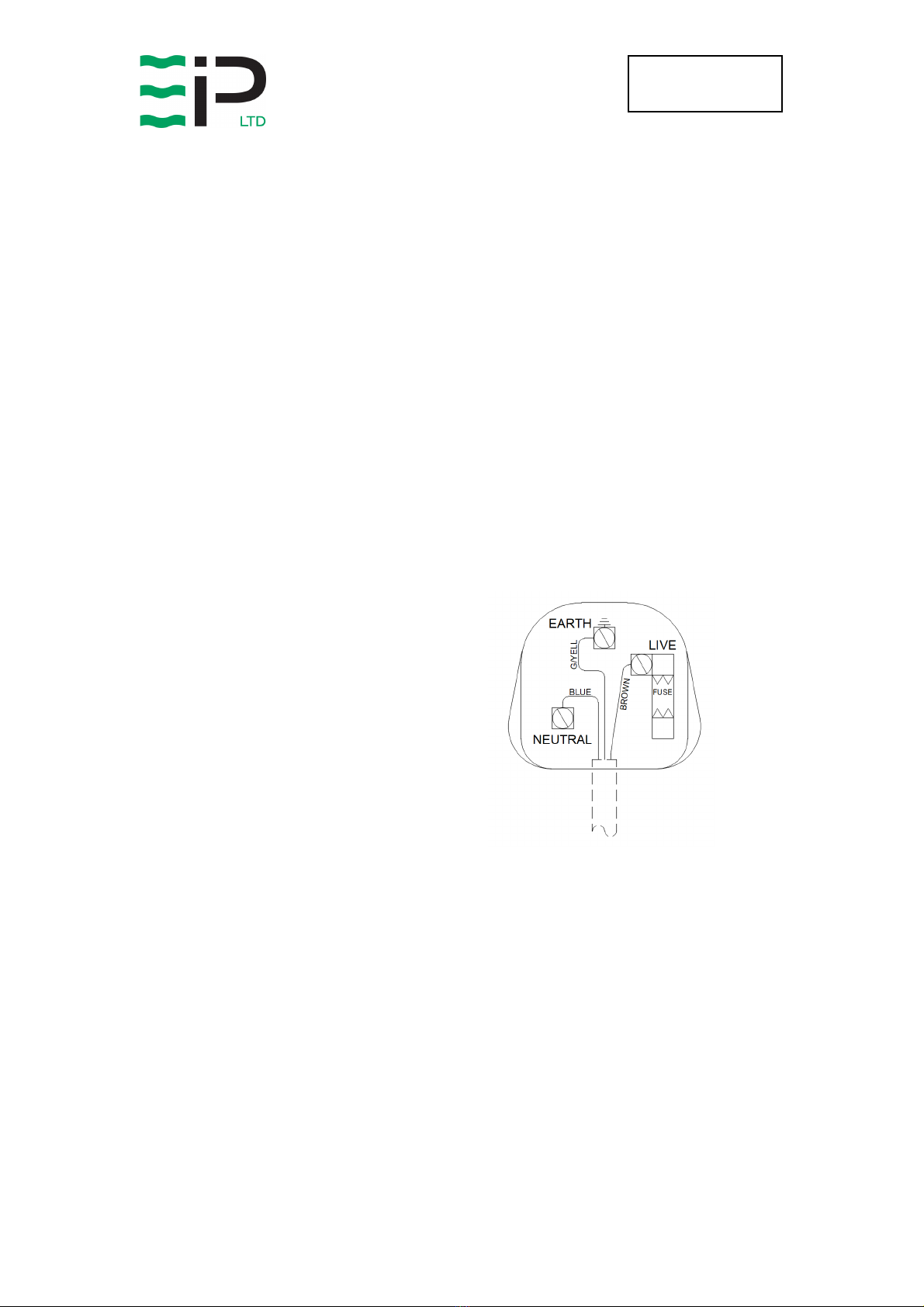
WIRING:
Connect the power mains cable to a 13 Amp power supply as follows: -
230V supply
Brown Live
Blue Neutral
Green/Yellow Earth (ground)
DRAINAGE:
The appliance is fitted with a condensate pump which collects all the
condensate. As the condensate pump fills with water it will automatically
activate and empty via the tube outlet located at the back of the dehumidifier,
this should be connected to a water container or permanent drain. If the pump
fails, then the dehumidifier will automatically switch off. NOTE: after the pump
has emptied there will still be a small amount of water standing in the pump
reservoir which will leak if the dehumidifier is not kept upright.
13 AMP 230V PLUG BS1363
13A

Page 6 of 12
Drawing : - TPC601
Issue : - 1
Date : - 08/06/23
HM150-H Dehumidifier Control Panel
Indicator
Function
Description
ON/OFF Red – Off
Green – On
Drying / Recirculation
Blue – Flashing – Drying Required
Blue – Solid – Drying On
Green – Solid – Recirculation Mode Fan Only)
Defrost Yellow – Flashing – Defrost mode selected
Yellow – Solid – Defrosting in progress
Alarm Green – Flashing – Pump Purging
Red – Solid – Fault, Pump Malfunction
Button / Ledgend Function Description
ON / OFF Switch the dehumidifier ON/OFF
Menu
Cycle through menu options and adjust the
desired set point. See below for list of menu
options
Recirculation Select recirculation fan or dehumidification
mode
Pump Purge Empty the integral water reservoir to prevent
spillage when moving / transporting
Navigation
Adjust the humidity set point UP/DOWN and
enter to confirm

Page 7 of 12
Drawing : - TPC601
Issue : - 1
Date : - 08/06/23
Menu Options
Pressing the Menu button cycles through the following pages of information.
Menu Options when dehumidifying mode is selected
Menu Display Information
1 Set RH Using the Up / Down Keys adjust the humidity to the desired
set-point, pressing the Enter key to accept and save.
2 Temperature Indicates the current room temperature.
3 Coil Temp Shows the current coil temperature. < -9degC display “—“)
4 Time To Start Displays the time to start drying mins) or “on” if already
drying
5 Time To Defrost
If defrost mode is selected, this option shows the remaining
time until defrost will occur. The yellow defrost light will be
flashing indicating a defrost is required.
If defrost is currently occurring, the yellow defrost light will be
solid, and the display will show the time remaining before
defrost ends.
Defrost not required or active the display will show “—“
Notes on Time values above
2 digits no decimal point indicates a time > 10mins
2 digits with a decimal point indicates mins and tenths of a min, ie 8.5 = 8mins 30 secs
Menu Options when recirculation mode is selected
Menu Display Information
1 Humidity Indicates the current room temperature.
Operation
Extend the short piece of tubing from the rear of the dehumidifier with the additional length
supplied using the “Quick Disconnect” coupling. Place the end of this tube into a suitable
drainage point, ie bucket, sink, toilet etc. Ensure the tube is not kinked or restricted.
Plug the unit into a suitable wall socket and power on.
Note the Power On Indicator shows Solid RED.
Press the ON/OFF button once to start the dehumidifier, pressing again will stop the
dehumidifier. To prevent the compressor starting too quickly after being powered down,
there is an inbuilt compressor off timer. This delayed start prevents the compressor for
restarting for 6 minutes after being switched off.

Page 8 of 12
Drawing : - TPC601
Issue : - 1
Date : - 08/06/23
The dehumidifier remembers the last mode of operation, and also the previously adjusted
set point.
Once the dehumidifier is started, the drying / recirculation light will indicate the selected
mode or operation.
Adjust the mode, as required. Recirculation or Drying).
In drying mode, the display will show the room humidity level.
In recirculation mode the display shows the current room temperature.
Using the Menu Key cycle through the menu options to the Set RH page, using the up/down
and enter keys adjust the humidity to the desired level.
The dehumidifier will now self-regulate to maintain the desired humidity level. The unit will
automatically defrost as needed. In warmer climates defrost is not required, allowing the
dehumidifier to continually dry.
Moving / ransporting the unit
The HM150-H has an inbuilt reservoir, which contains a small amount of water, therefore its’
advisable to allow any frost to melt, and empty this reservoir prior to moving.
Instructions / sequence
Switch the unit off by the control panel ON/OFF switch
Allow approximately 30mins for any frost / ice to melt
Press the Pump purge switch inorder to expel all water in the reservoir. The switch
may need pressing several times to ensure all water has been expelled
Remove from the plug from the wall socket and disconnect the drain tube
The unit is now ready to be moved / transported. Note the unit should be kept
upright at all times.
If, after carrying out the above procedures, the appliance does not
appear to function properly, refer to the Trouble Shooting section, which
follows, or contact EIPL.

Page 9 of 12
Drawing : - TPC601
Issue : - 1
Date : - 08/06/23
ROUTINE SERVICE
WARNING:
ENSURE THE POWER CORD TO THE APPLIANCE IS DISCONNECTED
BEFORE CARRYING OUT ROUTINE SERVICE. SERVICING AND REPAIR
SHOULD ONLY BE CARRIED OUT BY A SUITABLY QUALIFIED PERSON.
To ensure continued full efficiency of the appliance, maintenance procedures
should be performed as follows:
1. Clean the surface of the evaporator and condenser coils by blowing the
dirt out from behind the fins with compressed air. Hold the nozzle of the
air hose away from the coil (approx 6”) to avoid damaging the fins.
Alternatively, vacuum clean the coils.
WARNING:
DO NOT STEAM CLEAN THE REFRIGERATION COILS
2. Check that the fan is firmly secured to the motor shaft and that the fan
rotates freely. The motor is sealed for life and does not require any
lubrication
3. To check the refrigerant charge, run the appliance for 15 minutes. The
evaporator coil should be evenly frost coated across its surface. At
temperatures above 25°C, the coil may be covered with droplets of
water rather than frost. Partial frosting accompanied by frosting of the
thin capillary tubes, indicates loss of refrigerant gas or low charge.
4. Check all wiring connections.
TROUBLESHOOTING
S
YMPTOM
C
AUSE
R
EMEDY
Little or no airflow
1. Loose fan on shaft
2. Fan motor burnt out
3. Dirty refrigeration coils
4. Loose electrical wiring
5. Control humidistat either
set too high or
malfunctioning
1. Tighten fan
2. Replace the fan motor
3. See Routine Maintenance
4. Check the wiring diagram
to find fault and repair
5. Adjust humidistat as
required or replace
Little or no water
extraction
1. Insufficient air flow
2. Compressor fault
3. Loss of refrigerant gas
1. Check all of the above
2. Contact EIPL
3. Contact EIPL
Little or no defrost
when required
1. Faulty Timer
2. Faulty bypass timer
1. Contact EIPL
2. Contact EIPL

Page 10 of 12
Drawing : - TPC601
Issue : - 1
Date : - 08/06/23
SPECIFICATIONS
M
ODEL
:
HM150-H
H
EIGHT
:
470 mm (18.5 in)
W
IDTH
:
465 mm (18.3 in)
L
ENGTH
:
680 mm (26.8 in)
W
EIGHT
:
43Kg (95 lb)
A
IRFLOW
:
700 M
3
/Hr
P
OWER
S
UPPLY
:
230 V, 1 ph, 50 Hz
F
INISH
:
Rotational Moulded
polyethylene
R
EFRIGERANT
T
YPE
/Q
TY
:
R454c (See unit rating
label for quantity)
O
PERATING
R
ANGE
:
3°C – 35°C
Page 11 of 12
Drawing : - TPC601
Issue : - 1
Date : - 08/06/23
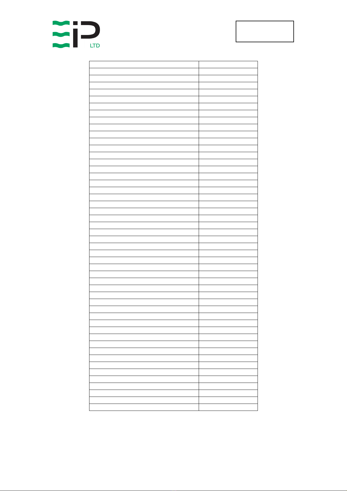
APPLIANCE SPARE PARTS LIST
Spare parts available online
www.EIPLDIRECT.com
Description
Part Number
Product Part Number
11580RH-GB
PCB - Timer
1619522
PCB - Humidity Sensor
1619526
PCB - Display
1619529
PCB Connecting Cable
2013748
Mains Cable
2029217
Foam Block
2056028
Refrigeration Coils
2158002
Keypad Label
2158028
Filter
2158036
Charge Valve
3014215
Capillary Tube
3014254
Foam Tape (Inseal)
3015199
Reversing Valve
3020833
Filter Dryer
3020958
Solenoid Coil
3030454
20mm Open Grommet
3032101
3/8” Open Grommet
3032102
12.5mm Open Grommet
3032104
25mm Open Grommet
3032111
Mains Lead Klambush
3032501
Pump High Level Float Switch
3033043
Mains Supply Filter
3033618
Coil Sensor
3035142
Humidity Sensor Housing
3035164
Circuit Board Jumper
3035834
Fan
3040280
Fan Inlet Ring
3040284
Wheel
3050125
Knurled Hand Wheel – M4
3080190
Starlock Washer Uncapped
3082610
Starlock Washer Capped
3082611
Hose Snapper Clip (SNP6)
3086136
Quick Release Tube Coupling
3086144
Hose Snapper Clip (SNP8)
3086146
Handle Spacer Washer
3087727
Handle Pivot Bolt
3088580
Handle Pivot Nut
3088594
Handle Retainer Catch
3088595
Circuit Board Support
3101413
Non Return Valve
3160157
Condensate Pump
3160162
Solid State Relay
3931320
LED Light Pipes
3931732
Compressor Capacitor
3933604
Humidity Sensor Cable
3935420
Condensate Outlet Tube
3944110
Condensate Reinforced Pump Tube
3944113
Compressor
3944965

Page 12 of 12
Drawing : - TPC601
Issue : - 1
Date : - 08/06/23
UK Head Office
Ebac Industrial Products Ltd
St Helens Trading Estate
Bishop Auckland
County Durham
DL14 9AD
Tel: +44 (0) 1388 664400
Fax: +44 (0) 1388 662590
www.eipl.co.uk
American Sales Office
Ebac Industrial Products Inc
700 Thimble Shoals Blvd.
Suite 109, Newport News
Virginia, 23606-2575
USA
Tel: +01 757 873 6800
Fax: +01 757 873 3632
www.ebacusa.com
Table of contents
Other EIPL Dehumidifier manuals


