Ekssperimental Sounds ES101 User manual
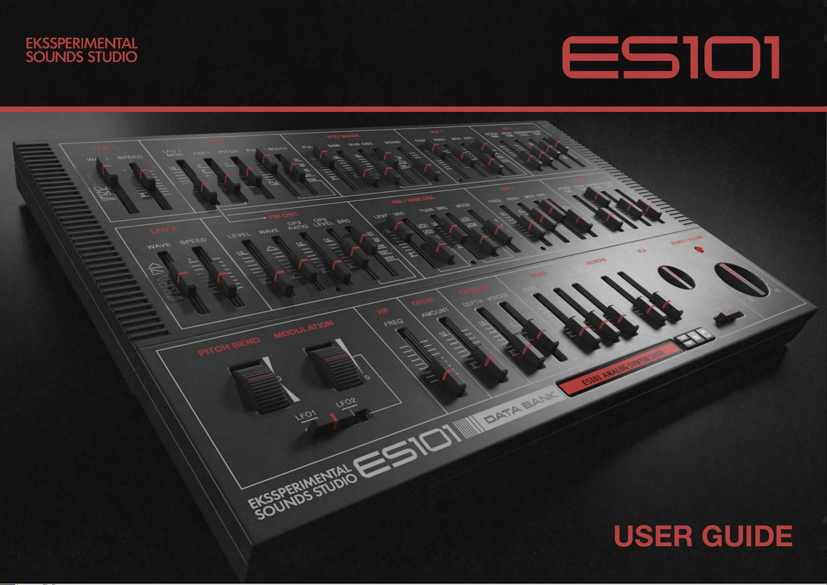
USER GUIDE
Thank you for choosing Ekssperimental Sounds ES101 Analog Synthesizer.
The ES101 incorporates advanced synthesizer technology and features
developed for the Reason rack environment with the added convenience and
versatility of CV controll of parameters via input jacks on the back panel.
We urge you to read this user guide thoroughly in order to make the most of
your ES101 Analog Synthesizer.
INTRODUCTION
VOLUME
This control serves the dual function of volume control and note indicator.
Rotate clockwise to increase Volume. The LED will ash when ES101
receives notes via CV Gate or MIDI.
VOICES (Back panel)
The ES01 can either be played in Polyphonic mode (16 voices) or in
monophonic mode (1 voice)
VEL SENS (Back panel)
Modulate output volume by the velocity of played notes
GLIDE (Back panel)
Creates a glissando between notes played. Can be set to OFF, ON or
AUTO. In AUTO mode the glide only happens when two notes overlap,
i.e when played Legato. Time trimmer is used to set desired glide time.
Important!
Each triggered note will remember it’s modulation source until release.
When using MOD SRC selectors the change is noticed on the rst new
note after source has been set.
BASIC SETTINGS

LFO stands for Low Frequency
Oscillator and can be used
for tremolo, vibrato, sweeps,
repetetive or randomizing effects.
WAVE
Select one of 6 waveforms for
each low frequency oscillator.
SPEED
Set the speed from S (slow) to F
(fast). Speed can be modulated via
CV input on the back panel.
RETRIG (Back panel)
Retrig the LFO for each new note.
SYNC (Back panel)
Sync the LFO speed to BPM
LFO 1&2
Triangle
Saw Down
Saw Up
Pulse
Random
Saw Exponential
Triangle
Saw Down
Saw Up
Pulse
Drift
Saw Exponential
WAVEFORMS LFO 1 WAVEFORMS LFO 2

LFO1 MOD
The LFO1 signal can be used to
modulate the pitch of VCO and FM
OSC with this fader.
FEET
This selector determines the ground
range of the ES101 VCO and FM
OSC.
PITCH
This is the ES01 tuning control It
permits a tuning of -/+50 cents so
that you can match the pitch of
PULSE WIDTH
These two faders can be used to
control the PULSE WIDTH. When
set to MAN the pulse can be varied
manually between 10% and 50%
width. When set to the EG1, EG2,
LFO1 or LFO2 positions the width
is controlled by the shape Envelope
Generators or Low Frequency
Oscillators.
This function varies the width of
the pulse in each cycle determined
by the speed set by the PWM
SPEED control. This function can
be used to create a variety of cho-
rus-like effects and add organic
feel to your tones.
VCO MIXER
Mix the waveforms produced by the
VCO, the sub oscillator signal and
the noise generator signal.
The Voltage Controlled Oscillator is the basic sound generator of the ES101.
The pitch of its signal is determined by the input of CV and MIDI message from your keyboard or sequencer.
VCO
Pulse Width Modulation
50% Pulse Width 10% Pulse Width

FREQ
Setting the VCF to the “H” end
allows upper harmonics to pass,
thereby creating a bright tonality.
Moving the control towards the
“L” end of the scale gradually cuts
off more and more harmonics,
creating a softer tonality.
RESO
Set to the “H” position frequencies
near the lter cut off frequency are
emphasized for a “sharper” sound.
When set high the lter will self
resonate (level will decreased as
the input signal is increased).
KBD (Back panel)
Control the cut off by following the
signal of notes played.
VEL SENS (Back panel)
Control the cut off by following the
velocity of of notes played.
TRIMMERS (Small panel holes)
Fine tune the cut off frequency.
This is convenient for ne tuning
when using the VCF as an sine
wave oscillator by self oscillation.
VCA LEVEL
This knob determines to what
degree EG1, EG2 or LFO2 affects
the level of the sound (dB). Chose
which source to use with the 3 way
selector below.
The Voltage Controlled Filters alters the sound by cutting off frequencies. Voltage Controlled Amplier
VCF 1 & 2 VCA
FREQUENCY
24dB/oct MOD & SRC
Determines to what degree the
signal of the EG or LFO affects
the VCF cut off frequency. This
permits creation of a broad range
of interesting time-based tonal
variation effects.
Envelope Generator affecting VCA
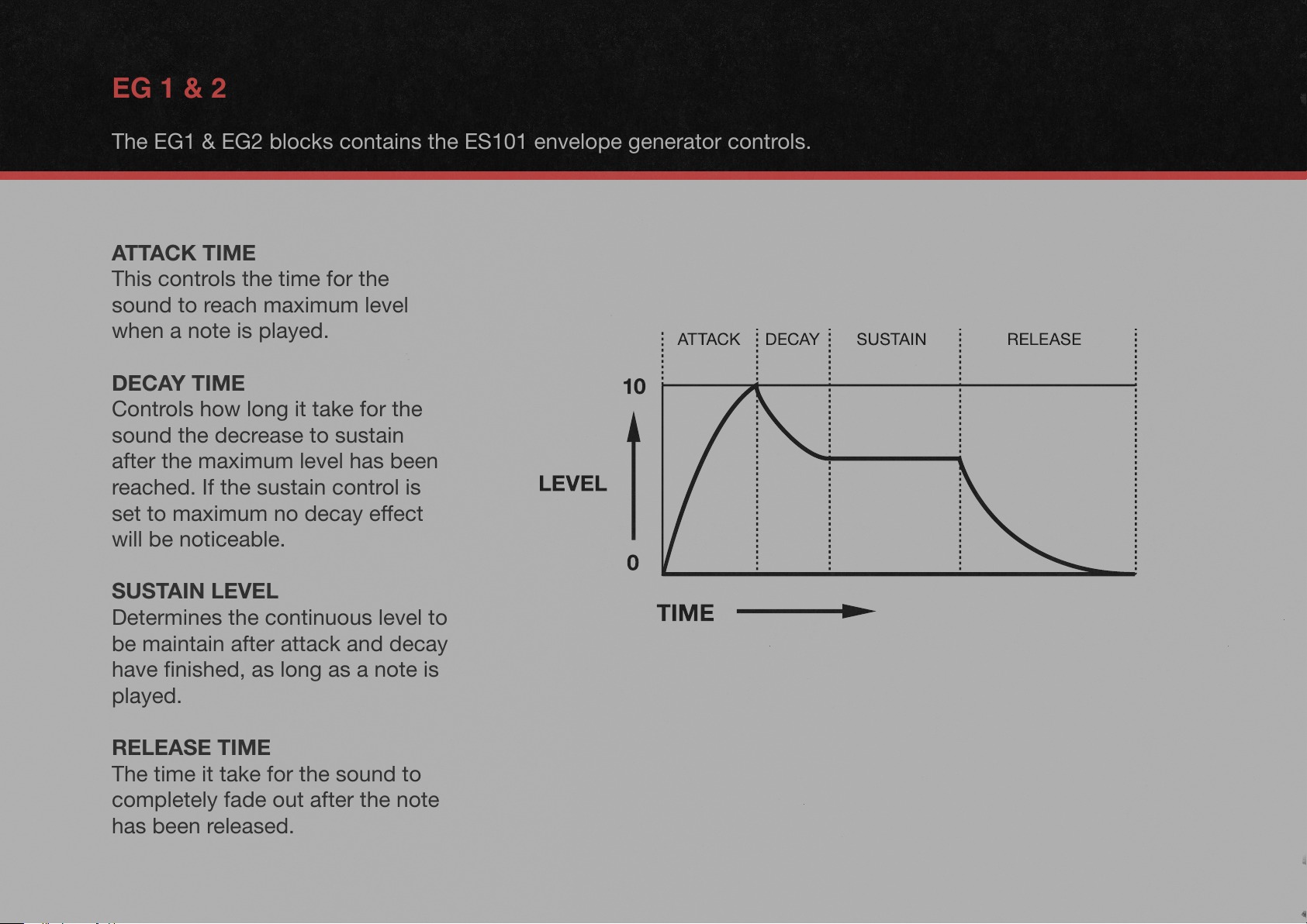
ATTACK TIME
This controls the time for the
sound to reach maximum level
when a note is played.
DECAY TIME
Controls how long it take for the
sound the decrease to sustain
after the maximum level has been
reached. If the sustain control is
set to maximum no decay effect
will be noticeable.
SUSTAIN LEVEL
Determines the continuous level to
be maintain after attack and decay
have nished, as long as a note is
played.
RELEASE TIME
The time it take for the sound to
completely fade out after the note
has been released.
EG 1 & 2
The EG1 & EG2 blocks contains the ES101 envelope generator controls.

LEVEL
This fader controls the level of
operator 1 and thus the overall
level of the FM oscillator.
WAVE
This fader will shape the wave form
of OP1 from Sine to Triangular.
OP2 RATIO
Controlls the frequency of OP2.
On the back panel you will nd an
offset trimmer for OP2 ratio.
OP2 LEVEL
The amount of modulation.
OP2 LEVEL SRC
Scale the level manually (MAN) or
by envelope generators or LFOs.
OP2 WAVE (Back panel)
Switch OP2 wave form from Sine
to Tringular.
FM OSCILLATOR
2 Operator frequency modulation oscillator
OP1 SIGNAL
OP2 SIGNAL
FM MODULATED SIGNAL
TRIMMER (Panel small hole)
Used to ne tune OP2 Ratio.
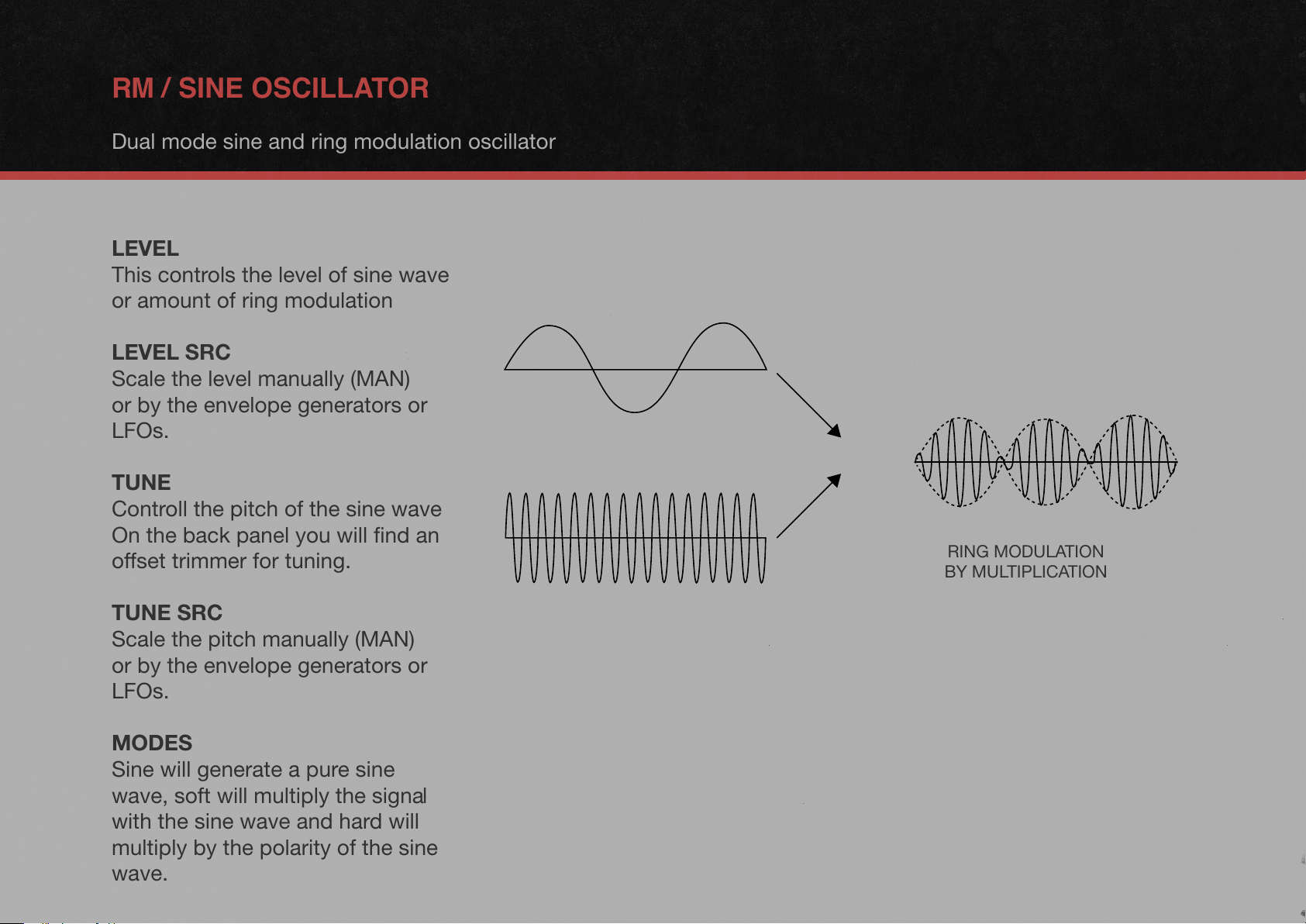
LEVEL
This controls the level of sine wave
or amount of ring modulation
LEVEL SRC
Scale the level manually (MAN)
or by the envelope generators or
LFOs.
TUNE
Controll the pitch of the sine wave
On the back panel you will nd an
offset trimmer for tuning.
TUNE SRC
Scale the pitch manually (MAN)
or by the envelope generators or
LFOs.
MODES
Sine will generate a pure sine
wave, soft will multiply the signal
with the sine wave and hard will
multiply by the polarity of the sine
wave.
RM / SINE OSCILLATOR
Dual mode sine and ring modulation oscillator
RING MODULATION
BY MULTIPLICATION
X =
TRIMMER (Panel small hole)
For extreme ne tuning on high
frequencies. When TUNE is set
low this trimmer will have an
almost unnoticable effect.
FREE/KBD (Back panel)
This oscillator is independent of
the Feet selector but will follow the
keyboard when set to KBD.

FLOW SCHEMATIC
Graphic representtion of the signal ow scheme
CV INPUTS
The CV input jacks are directly
connected to the parameter
marked on the panel.
Using CV jacks allows for multiple
modulations of one parameter.
As an example you can use LFO1
to modulate VCF Cut off with the
faders on the panel, and send
EG signal via CV to the same
parameter.
CV OUTPUTS
Notice that the EG CV Signal
output is slighlty smoother then
the internal direct connections. For
extra snappy and quick envelope
modultion internal routing is
adviced.

EFFECTS
The ES101 has build in effects for easy sound design
HP
High pass lter to cut unwanted
bass frequencies.
DRIVE
Create saturation and overtones
with this fader.
CHORUS
Create width and richness by
increasing the depth fader. Select
from 2, 3 or 4 voices with the
voices fader.
ECHO
Rate is the time relation between
echos. FB controlls the feedback
amount, i.e how many repeats of
the echo. Mix will fade from 0% to
100% echo.
On the back panel you will nd a
switch for echo SYNC mode and a
dampening trimmer
REVERB
The Decay fader will control the
length of the reverb from short to
long.
Use the Mix fader to blend in the
reverb, from 0% to 50% reverb.
On the back panel you will nd
controls for tonality (Bright/Dark)
and a low cut trimmer to easily cut
away rumbling bass frequencies.

Concept and GUI by EKSSPERIMENTAL SOUNDS STUDIO
Created with IDT/GE Technology
Thanks to: buddard, IDTdev, jengstrom, MrFigg
©2020 EKSSPERIMENTAL SOUNDS STUDIO
www.ekss.se
Table of contents
Other Ekssperimental Sounds Synthesizer manuals


